To avoid these ads, REGISTER NOW!

Quincy 210 ROC-3 rebuild(s)

Thague90

Member
Joined
Aug 28, 2016
Messages
24
Location
Michigan
I’ve shown this compressor a number of times in the compression thread. I figured it was time for it’s own build thread given the number of times I’ve reworked it. For the sake of continuity I’m going to copy some of the other posts to here before I start posting on my current progress. I hope that doesn’t break any rules (too badly).

IMG_6884.JPG
 
To avoid these ads, REGISTER NOW!
OP
T

Thague90

Member
Joined
Aug 28, 2016
Messages
24
Location
Michigan
I picked up an air receiver which was being used at a carpet factory in north GA. Tank is Rated at 200 PSI, came with inspection papers, hi-volume safety valve, and was clean on the inside.

8dce7d8bbf0c6d3e2bdea10a3431d0cf.jpg

I’ve been looking for a standing tank for my old revision 3 Quincy 210 to sit on. I had it rigged up on a horizontal craftsman 30 gal tank but that tank went to ****. It got a pinhole leak away from the drain hole (craftsman tank was too far gone when I bought it and just kept rusting). Because of my distain for all things rust, I chose to do several coats on the inside of this tank with some Rustoleum enamel (1qt primer used, and 1.5 qt enamel) 5 coats of paint over the course of a week. Then I let it air out for about 2 weeks baking in my garage in the TN heat.

ec913ab9f47c8c81eb6829786dfed410.jpg

be47a44bfcb3b0053b488c33e708d4d7.jpg

(Insert pic of painted inside here)

I’ve got the pump, motor, and cooler mounted up, still working out how I’m going to do the plumbing. I’m trying to make it look nicer than just a hodgepodge of pipe and wires, so I’m taking my time with it; just a bit of time every couple days after work when I can.

c7e1b5b092e5e4dbc700584b68762459.jpg
 

Attachments

  • ec913ab9f47c8c81eb6829786dfed410.jpg
    ec913ab9f47c8c81eb6829786dfed410.jpg
    67.2 KB · Views: 3
  • 8dce7d8bbf0c6d3e2bdea10a3431d0cf.jpg
    8dce7d8bbf0c6d3e2bdea10a3431d0cf.jpg
    89.7 KB · Views: 2
  • be47a44bfcb3b0053b488c33e708d4d7.jpg
    be47a44bfcb3b0053b488c33e708d4d7.jpg
    10.5 KB · Views: 2
  • c7e1b5b092e5e4dbc700584b68762459.jpg
    c7e1b5b092e5e4dbc700584b68762459.jpg
    128.5 KB · Views: 4
OP
T

Thague90

Member
Joined
Aug 28, 2016
Messages
24
Location
Michigan
Working on some industrial equipment peaked my interest in automating the controls on a compressor. On and off just isn’t good enough for me anymore. So while laid up on the couch with a hamstring tear, I came up with this.

IMG_7118.jpg

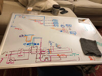
I don’t know much about how to draw this stuff, basically just what I found on google pictures, so forgive the crudity/mistakes.

Everything is powered from the breaker box. Line power will also come in as a signal from the light switch (overhead light circuit). This way it will run when I’m there and shut off (mostly) while I’m gone.

My idea is to use a digital pressure switch with 2 outputs to control the compressor, cooler fan, and a head pressure relief valve on one output. The tank drain will be an open/closed valve of some sort with a timer circuit on output 2.

Output 2 won’t come on untill the compressor cycles to full pressure, and will latch the power for the drain timer untill the tank pressure drops below a certain amount. This way the tank will continue to drain while I’m gone and give the compressed air time to condense... and drain.

When I turn on the lights again, the compressor won’t run untill I hit the start button which will turn on the first contractor and the 24v power supply for the relays and stuff.

So... whatcha think?

Also, this is what it looks like put together. Cable management needs work, but I’m learning.

IMG_7133.jpg

Still figuring out how I’m going to attach it, but this spot looks promising. Right under the cooler/fan.

IMG_7134.jpg
 
OP
T

Thague90

Member
Joined
Aug 28, 2016
Messages
24
Location
Michigan
I have an air cooler coil I took out of a broken air dryer that was on its way to disposal. It has its own containment and a cage for the belt operated fan. I replaced the belt pulley with a small motor from a damaged personnel fan. Only needs 100 watts to run so it does not add much to the motor circuit.

Here are a couple of shots of the setup as it sits now. As soon as I think I have it put together... I find something else I want to improve and take it apart again.

56221909828__6F4C1FA1-B1DC-41DC-8F05-92DDC4C17196.jpg

IMG_6995.jpg
 

PT Doc

Well-known member
Joined
Nov 12, 2010
Messages
3,197
I have never seen anytone paint the interior of the tank. Have you done that before? Thanks
 
OP
T

Thague90

Member
Joined
Aug 28, 2016
Messages
24
Location
Michigan
I see a flaw in the design... if somebody leaves the lights on the crime is doubled by leaving the compressor energized, even though if your pneumatic system is leak proof it will never cycle anyway, but one contactor coil will be wasting a quarter kilowatt hour a day for no reason, therefore my suggestion would be to add a motion detector in series with the “lights on” signal to make sure somebody is actually moving about the shop before energizing the other components of your master compressor control system.


Is there a better way to have my system latch than the first contactor? I have had this nagging feeling about it since I started, but could not figure out how to make it work the way I wanted it to without the 110v operated contactor acting as a relay? I’m kind of teaching myself about this stuff so I am wide open for suggestions/critiques. Having found about 3 other things I don’t like about it, I am about to wipe the drawing board and start over.

b524b3e2c48657495f34447edb2aee84.jpg

Yes... the picture was completely necessary!
 

Attachments

  • b524b3e2c48657495f34447edb2aee84.jpg
    b524b3e2c48657495f34447edb2aee84.jpg
    350.5 KB · Views: 2
OP
T

Thague90

Member
Joined
Aug 28, 2016
Messages
24
Location
Michigan
I have never seen anytone paint the interior of the tank. Have you done that before? Thanks


Yes I have. I helped a family member do it on their compressor when I was younger. He checked it several years later and the paint was still holding up, thus, not a speck of rust. I have heard many arguments for and against painting, but what I have come up with is overdoing the prep, primer, and paint covers any shortcomings of painting the interior. The tank has to be etched or roughed up somehow. I used gravel and drywall screws while it rotated on the casters I setup. It scuffed up the sides plenty but I had to rotate it on an angle to get it to scuff the top and bottom of the tank. BTW, It had to rotate it for 2 hours straight to make enough of a difference.

3 coats of primer and 3 coats of paint and then I let it dry for 3 weeks. To help things along, I put a small squirrel cage blower in one of the tank bungs and left the rest open. Yes... for 3 weeks. I didn’t want to risk any puddled up paint staying wet. I was religious about checking for paint coverage while I turned the wet paint around inside. Any defect, Even one spot, would allow water a way behind the paint layers and ruin the tank. There is a risk to painting the tank, but I believe that I went above and beyond to circumvent those risks.
 
OP
T

Thague90

Member
Joined
Aug 28, 2016
Messages
24
Location
Michigan
I just noticed that if my drain circuit is on then line from the wall makes its way to line on my light switch and power will remain supplied to my lights... through far too small of a wire. I’m glad I didn’t set this up yet. Back to the drawing board figuratively... because literally... I’m sitting in front of a now blank whiteboard.


Sent from my iPhone using The Garage Journal mobile app
 
OP
T

Thague90

Member
Joined
Aug 28, 2016
Messages
24
Location
Michigan
I’ve got the feedback issues resolved. Mainly by using the light switch “signal” only to power a 110v contactor coil. All I have that will run on 110 currently is that 2hp contactor, but I could make do with (and plan to use eventually) a dpst solid state relay as the current requirements are low. Ultimately I will only use the one 24v contactor to supply power to the motor.

My other regret is my “dual timer” setup for my auto-drain is actually two separate on-delay 8 pin timers which take up a large amount of space in my box. I would prefer to swap them out for something with a smaller form factor. But I’m working with what I’ve got for now.

I’m using industrial 4 pin cable connections and am running individual cables to each of the components. Almost done with the rebuild, just running out of steam tonight.

IMG_7614.jpg

And... the wiring diagram is cleaning up a bit. If only because I got lazy and quit drawing return lines to the DC + & - buss bars. Just make the connections and it’s all there... I think. Haven’t tested it yet so... who knows.

IMG_7615.jpg
 
Last edited:
To avoid these ads, REGISTER NOW!

matt_i

Well-known member
Joined
Mar 14, 2008
Messages
10,717
Location
SE Michigan
I can see you have put a lot of thought and time into this. Good stuff there to push the envelope, great way to learn :)

Couple of free suggestions...its easier for an outsider to follow your controls if you put the wiring diagram into ladder logic format. The wiring diagram you have is not a bad thing, it shows the wire routing and how the components interact, but is harder to follow from a "this causes that" analysis of how it works.

I also see that you mentioned needing to use a Start pushbutton to start the cycle, you mentioned a 'latch' which is probably closer to a "seal circuit" as opposed to a "mechanically latching relay". Consider that the lighting on or off is already a maintained signal, and so if you use it for an "enable" signal for your other process, then there's no need to hold the contacts in, the voltage applied to the lights will do it as long as the lights are on. Just pointing out really that it could be "hands off" and not need the human memory to go over and take a trip to start up the compressor cycle.
 
OP
T

Thague90

Member
Joined
Aug 28, 2016
Messages
24
Location
Michigan
Consider that the lighting on or off is already a maintained signal, and so if you use it for an "enable" signal for your other process, then there's no need to hold the contacts in, the voltage applied to the lights will do it as long as the lights are on.


The start button is meant to prevent the compressor from turning on from the get-go. I get into the shop often enough without needing air so I wanted to have the system off untill I needed it. Also... I found a really cool button that I was dying to use somewhere.

IMG_7616.jpg

As for the use of the contactor (soon to be relay) when the auto drain is running, I wanted the system to remain on so it can continue to drain while I’m gone, but only untill the pressure drops below a certain point. To do this I used a second output on the pressure switch to latch (mechanical relay) power to the 24v power source so the system will stay on even when the lights turn off.
(Back to the point)
The purpose of the first contactor is to prevent line voltage from the wall from making its way back to the lights when the auto drain was on. (Stoping the lights from turning off)
 
OP
T

Thague90

Member
Joined
Aug 28, 2016
Messages
24
Location
Michigan
Got it running!!! Controls work perfect! Push button start. Pump on below 100psi, and off at 135psi. Auto drain opens for 0.5sec every 3 hours from 135psi down to 110psi and the system shuts off if the overhead light circuit is off. My cable management is pretty poor currently, but I’m planning on tightening things up once I pick a spot for everything.

The E-Stop box isnt mounted yet, but it kills power to all systems and does not restart the system when you pull it back out. Instead the E-Stop reset is the green button next to it.

IMG_3319.jpg


Sent from my iPhone using The Garage Journal mobile app
 

bad_idea

Well-known member
Joined
Jun 11, 2011
Messages
4,329
Location
Pasquotank, NC
Cool. What is the plan for the tank drain? Plumbing it to the exterior or a catch pan? Do you have plumbing drains in the garage? Would be cool to have the tank drain dump into a tank and then a small pump pump it to the plumbing drain. Like the condensate pumps you can get for your ac drain.

How did you tie it into the lighting circuit? I would like the ability to control a couple things in the garage in sync with the lights.
 
OP
T

Thague90

Member
Joined
Aug 28, 2016
Messages
24
Location
Michigan
Cool. What is the plan for the tank drain? Plumbing it to the exterior or a catch pan? Do you have plumbing drains in the garage? Would be cool to have the tank drain dump into a tank and then a small pump pump it to the plumbing drain. Like the condensate pumps you can get for your ac drain.

Even in the most humid weather, with the chiller/dryer setup that I have, I barely get any condensation in my tank. At one point I had thermocouples in the output of the pump, the exit side of the chiller, and one inside the tank. The air coming from the pump was HOT depending on the day I measured low 300’s Fahrenheit. But coming out of the chiller it was in the high 60’s F... it was 78F that day. So the compressed air actually has to heat up when it finishes.
(I still have a video of those results somewhere, but I can’t find it right now.)

Long story short, almost all of my condensation is separated before it gets into the receiver. It drains out of a pretty basic filter/separator which I have plumbed right after the chiller. It drains each time the unloader valve opens up. This was the important part of the whole chiller setup.

IMG_3322.jpg

How did you tie it into the lighting circuit? I would like the ability to control a couple things in the garage in sync with the lights.


The power from the lighting circuit comes in separate from the main power cable. The only thing the lights power is this single 2hp contact operated on 110v AC. That contact allows the main power to pass through to the second contact which the pressure switch controls on 24v-dc. There are some other latching loops and timing in there for the drain setup, but the main thing is; the motor power is disconnected when the lights go out.

IMG_3323.jpg

The only reason the drain can still work is that I have a blade relay feeding 110v to the 24v power supply separately, bypassing the first contactor (only while the pressure switch is sending the drain signal) this keeps the 24v power supply on, but the motor still won’t operate if the lights are off and the 110v contact is disconnected/opened.

I should note that my pressure switch can send 2 separate signals which I use #1 to operate the pump motor, and #2 to operate the drain timer and the “drain latch” described above.

Sorry if I went a little overboard on the explanation, but that’s everything that I thought was pertinent.


Sent from my iPhone using The Garage Journal mobile app
 

bad_idea

Well-known member
Joined
Jun 11, 2011
Messages
4,329
Location
Pasquotank, NC
Panduit_Corporation_G1X3LG6_PANDUIT_G1X3LG6_original_3588679.jpeg


That's the best part about Panduit, it is very easy to make changes. Just lift the cover off and route the new wires through. No zip ties needed. You can also hide extra length of a wire in the pandiut to allow you to reroute things later if needed. We use a lot of it in controllers we build at work. I cut and fit the cabinets, I'm not a wire biter.
 
OP
T

Thague90

Member
Joined
Aug 28, 2016
Messages
24
Location
Michigan
I like the idea, but the sizes of panduit I have at work won’t fit in this box the way it’s laid out. One piece tight in the middle maybe, but no way it’ll fit on the bottom or the sides. I haven’t looked Into what thinner sizes cost. I’d like to swap out the timers for a single pulse relay to possibly free up some space. I’ve also considered a larger box which I could fit a manual disconnect into. Once I know the components, I could set it up with panduit to run along top/side/bottom of everything.

FYI... it got more complicated since my last picture. New GFCI outlets in my garage prevent me from sharing hot and neutral pathways between the light and wall circuits. Had to use a set of relays to switch between power from the lights and the wall when running the drain after the lights go out. All in all it’s becoming fairly complicated. Think I might be in the mood for another redesign.


Sent from my iPhone using The Garage Journal mobile app
 
To avoid these ads, REGISTER NOW!
Top Bottom