To avoid these ads, REGISTER NOW!

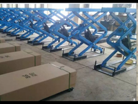
In ground flush mount scissor lift

Cyclehead

Well-known member
Joined
Jan 19, 2017
Messages
85
Location
Georgia
Hi, I’m a noob here. I’ve been slowly searching for a lift for my home garage. I looked at the “portable” two post lifts, and the slide-around style scissor lifts. I finally decided I want a flush mount scissor lift. I priced the ones available in US and I can’t stomach a $4000 price tag. So I scrounged alibaba and ordered one from Yantai China for $1400. I contacted a shipping outfit in nearby port (Savannah Ga) to handle all the port fees, customs, insurance etc. It looks like roughly $600 to pick up the lift from China and ship it to a local warehouse where they can fork lift it onto a trailer for me.

Negotiations with the factory in China have been...interesting. I’m using an alibaba.com app that I think translates from Chinese to English on the fly. The biggest hurdle so far is spec for a suitable motor for US power. Their normal motors are 220V and 380V (3 phase), both at 50hz. They are working on building mine with 110v 60hz motor. Communication is a very slow and tedious process.

If it all works - I’ll happily share company names, prices and details. If not, hmmm, I’ll probably lick my wounds and not say much. Meantime I have some questions please.

I’m trying to understand the requirements for the concrete pits in my garage floor where these things will live.

Question: Why is there need for crushed rock, compactors, rebar and 6-8 inches of concrete under a scissor lift?

My feeble mind sees my current garage floor which is barely 5 inches thick, poured on top of sand. No rebar, no crushed rock. I routinely support my entire car on jack stands with a footprint of... inches. These scissor lifts each have a footprint of something like 6 square feet! If I mounted them on the surface of my existing floor I presume they’d function just fine. The scissor lifts don’t rely on the floor mounting bolts for stability (unlike the cantilevered two post lifts). There will be very little prying action on the mounting bolts. So how come there are such extreme requirements for the floor of the pit? Do I really need crushed rock, compactors, rebar and 8 inch thick 5000psi concrete?

SUMMARY:
Purchase Price $1470.00 from Alibaba.com
Shipping and port fees $1123.00
Garage floor mod and concrete work $2500.00 (subcontracted out)
TOTAL: $5093.00
 
Last edited:
To avoid these ads, REGISTER NOW!

vavet

Well-known member
Joined
Mar 6, 2012
Messages
5,329
Location
Ashland, VA
I organized the group buy for 7 lifts from China last year for 6 people on this forum, I hope the $600 thing works out for you, but I’d plan on more. There will be transportation costs plus taxes, fees, duties, tariffs, etc once it arrives in the US. If the container your lift is in gets selected for additional screening, then that’s even more money. Maybe we got screwed on some of those and you’re getting the straight deal. Time will tell.
Good luck.
 

ConCretin

Well-known member
Joined
Jan 20, 2011
Messages
3,379
Location
Central Maine
I’m trying to understand the requirements for the concrete pits in my garage floor where these things will live.

Question: Why is there need for crushed rock, compactors, rebar and 6-8 inches of concrete under a scissor lift?

My feeble mind sees my current garage floor which is barely 5 inches thick, poured on top of sand. No rebar, no crushed rock. I routinely support my entire car on jack stands with a footprint of... inches. These scissor lifts each have a footprint of something like 6 square feet! If I mounted them on the surface of my existing floor I presume they’d function just fine. The scissor lifts don’t rely on the floor mounting bolts for stability (unlike the cantilevered two post lifts). There will be very little prying action on the mounting bolts. So how come there are such extreme requirements for the floor of the pit? Do I really need crushed rock, compactors, rebar and 8 inch thick 5000psi concrete?

The short answer is 'no'. As long as the soil you find when you dig down for you pits is stable, you'd be fine to place 4" pads with 3000 psi concrete for your lift. Most of us would be unable to resist some rebar pinned to the existing slab but the structural requirements are minimal. Good luck with your project.
 

jtbinvalrico

Well-known member
Joined
Jan 2, 2010
Messages
1,375
Location
Tampa FL
Why is there need for crushed rock, compactors, rebar and 6-8 inches of concrete under a scissor lift?


Understand that I’m no engineer and am also relatively new to this type of installation. I’ve been on this board for a while and can’t recall anyone regretting building too big, too strong, having too many amps, having the shop ceiling too tall, etc. Yet, for each of those guys, there’s another who saved money, spec’d the job just right, and is perfectly happy. For some, the scale of the project can dictate these factors. I put in a big 100 amp sub for my 3 car...far too much, but the cost for my short 60’ run was negligible; a guy running that out 200’ to his detached shop is maybe looking at that math a bit differently. My point: Sometimes overkill is not that much more, but sometimes it’s a pain point worth paying attention to. YMMV.

If you took the same scissor lift and compared its installation as a surface mount on an existing garage floor to its installation as a flush mount, I’d say that’s an apples to oranges comparison.

Here’s why. We can all readily picture the surface mount installation. But to consider the flush mount, we first need to remove that garage floor from consideration. We then need to envision that flush mount resting on two separate unattached 5’ x 2’ pads sitting on only the dirt that’s under your house. With that image in mind, begin to factor in the condition of that dirt. Consider that any imbalances in the load or the ability of either pad to bear its load will affect the whole contraption.

So why all the extra work? Compacting the dirt reduces the chance of settling and voids, which may not readily show themselves under a big single slab, but could be even less forgiving under two smaller footprints.

A crushed stone base acts as an interface between all that dirt and the concrete you put down. I don’t fully grasp it, but guys smarter than me say it essentially lets the concrete move or slide a bit as a whole, instead of cracking as one part of the dirt settles while another doesn’t. This stone is compacted as well to make it more of a solid unit, but also able to allow for some movement without cracking the whole slab. Concrete is going to settle and move, this is one way of predictably controlling that.

Rebar provides some backup strength, but in the forming of these pits a tub formed of rebar really serves to mechanically tie the existing slab to the sides and base. This locks the pits into the slab and to each other, now giving you that single, “unitized” effect readily seen in the surface mount example.

Do you “need” all that? There’s more than a few who didn’t bother with it. I could have been done with my installation by now if I had skipped those steps. I tend to overbuild and acknowledge that I may be doing that now. But, I’m not in a rush. The added expense of these steps is not prohibitive. And, I’ll never regret doing them.

My advice is to incorporate these steps into your build. Regardless, please share and chronicle your progress here. :beer:


Sent from my iPhone using Tapatalk
 
Last edited:
OP
C

Cyclehead

Well-known member
Joined
Jan 19, 2017
Messages
85
Location
Georgia
My lift is on a slow boat from China. It was scheduled to arrive Jan 15, now delayed until Jan 31. I don't think my back is up to moving busted concrete and mixing bags of sakrete, so I'm starting to price a contractor to cut, excavate and pour the bunkers.
My lightweight trailer and tow car aren't up to 1600 lb capacity, so I plan to make two trips to the local shipping facility to carry the three boxes home. Then set everything up in the driveway to assemble and test hydraulics before cutting anything.
 

ArkTinkerer

Well-known member
Joined
Dec 29, 2010
Messages
369
One thought on the concrete for the footings (I was one of the group buys). The lift company has a manual and tells you what they recommend. I suggest you follow it. Second, if one side sinks relative to the other, the change is the angle between the two amplified by the lift height. The further from vertical, the more the force to tip the lift(s). It is not a linear equation. You REALLY don't want one side to sink relative to the other. We also had issues with our delivery and quality from China. But even so, I think it was a good deal. Not as cheap as yours though. Good luck and post pics!
 
OP
C

Cyclehead

Well-known member
Joined
Jan 19, 2017
Messages
85
Location
Georgia
I finally have a local delivery date - next Monday, 18 February. Close to 5 months after I sent payment! I will pick up with my utility trailer at a local trucking hub. Communication with the supplier was abysmal. Details were exasperating to resolve, delays, wrong motor sent to them by their supplier etc. My lift finally left China on Christmas day. The "trade assurance" offered by Alibaba has expired, so whatever shows up in the boxes is mine. I still don't have the final price for shipping and trucking from the port in China. What an adventure!.
 
Last edited:

SJW

Well-known member
Joined
Apr 4, 2018
Messages
67
Location
Thousand Oaks, CA
Cycle, I'm wondering if we're talking about two different things regarding the concrete.

Scenario 1: You are going to pour an entirely new concrete garage floor with two cutouts in it for your flush mount lift. Assuming the lift is 4 inches high when completely flat, you might consider an 8 inch deep concrete floor so that you can put the lift frames into the holes and still have 4 inches of concrete depth below so that you can anchor the lift in place.

Scenario 2: You have a garage with a concrete floor that is 5 inches deep. Your plan is to put in two holes for the lift frames that are 4 inches deep, leaving only one inch of concrete, on sand, under the lift frames that are going to be supporting multiple thousands of pounds of weight. Clearly anchor bolts are out, they would go 2 to 3 inches into the sand and would thus be useless. If anything happened to that 1 inch of concrete under your lift frames, you could easily render your lift useless.

I think the crushed rock, rebar, 6 to 8 inches of concrete apply to Scenario 1, while the way I read your posts I think you're planning on going with Scenario 2. Obviously, correct me if I'm wrong.

Scenario 1 is clearly quite a bit of extra effort and money. Scenario 2 seems worrisome to me. If the sand does not hold evenly under the concrete cutouts, I think it is possible the lift could become unusable. Sorry if this is not good news.

Personally, if you aren't going to switch to Scenario 1, I think you should switch to using the lift above ground, not flush mount. Your 5 inches of concrete would be fine in this case. It's clearly not as convenient as flush mount, but all it would require would be ramps.

Just one person's opinion. Good luck!
 

buzzworth

Well-known member
Joined
Oct 22, 2007
Messages
936
Location
Louisville, KY
I had it all mapped out to do this same thing. I was going to do it myself but when I priced out the saw rental, labor to clean it out, and pour the concrete, I decided to see how much I could have a contractor do it for. Nobody was interested in such a small job.
I ended up buying a set of Race Ramps as my garage is mostly for storage and minor lift work, not major work on the cars. They are in four sections and about 10 lbs per piece so once the car is up it is easy enough to move the pieces out of the way.
And certainly less $$ and labor than digging a hole.
Just my solution...

https://raceramps.com/car-ramps/garage-and-service-ramps/4-car-lift-ramps-full-length/
 

gerryw

Well-known member
Joined
Aug 10, 2008
Messages
815
Location
toronto area
can you show a pic of what you bought?
I recessed mine (diy)
Want to make sure we are talking about the same thing
But a short answer your question “ do i really need to do all that work”
No you dont.I agree with your logic.
Gerry
 
Last edited:
OP
C

Cyclehead

Well-known member
Joined
Jan 19, 2017
Messages
85
Location
Georgia
Final Customs/service/congestion/freight/messenger/VGM/IFS/courier/duty and BS fees finally arrived today - the total is $1123.00. Lift purchase was $1470 for a grand total of $2593.00. So that's what I have invested so far - that plus 5 months of excitement. I'll be off to the local trucking hub later this week to see what I paid for.

I'm also getting quotes on cutting and pouring the bunkers. I don't relish the idea of lugging busted concrete, and I have zero experience pouring new. The first contractor said he'd lay down 12" deep concrete. No need to be stingy with the pour since I'd be paying for 5 yard minimum.

After measuring my car widths, I'm considering going with 26 inch spacing between lifts, instead of the 31 inch "recommended".
 
Last edited:
OP
C

Cyclehead

Well-known member
Joined
Jan 19, 2017
Messages
85
Location
Georgia
I bought the “MAS3018 In Ground Full Rise” lift from Yantai Automas. I would not recommend buying from them due to horrible communication, delays, missed dates, more delays etc. Here is the info I had when I selected this one.

8CD9B640-6A3B-4DDB-9DC9-E22183C51716.jpeg

EPPChKm.jpg

Gp9T1Jy.png
Gp9T1Jy.png
 
Last edited:

bad_idea

Well-known member
Joined
Jun 11, 2011
Messages
4,335
Location
Pasquotank, NC
As far as the 5 yard minimum - sounds like it's time to pour a patio. I'm sure you could use some extra concrete somewhere. A 10'x10' slab out in the backyard for welding/burning/grinding nasty stuff would be great. For what it is - a chunk of concrete to do dirty work on - frame it up yourself and have him pour it. Decent concrete guy shouldn't charge you any extra for dumping the concrete he's making you pay for in a form you put together.
 
OP
C

Cyclehead

Well-known member
Joined
Jan 19, 2017
Messages
85
Location
Georgia
As far as the 5 yard minimum - sounds like it's time to pour a patio. I'm sure you could use some extra concrete somewhere. A 10'x10' slab out in the backyard...

I mentioned this to my wife. She had NO problem coming up with lots of potential uses for some extra concrete!
 
OP
C

Cyclehead

Well-known member
Joined
Jan 19, 2017
Messages
85
Location
Georgia
After months of waiting, the last few days have been a whirlwind. I picked up the lift at the logistics warehouse on Wednesday. Borrowed an engine hoist to lift the pieces off my trailer yesterday. I’m getting estimates for the concrete work now - two so far. One contractor wants to have a mixer truck deliver (the 5 yard minimum mentioned earlier), another has a crew of guys that would mix on-site from bags. I’m very happy to be armed with the cautions from you guys about bowing forms, hydraulic route lines too small etc! Hopefully I can get this thing done without too many mis steps. Pictures are coming

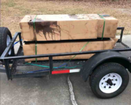
Loaded at the warehouse.
Note the nose of the trailer, and the box with pump are nosed down...
1679943334333.png

On the way home, oil started trickling out of the pump box...
1679943208519.png

I think the residual oil in the reservoir leaked out of the filler cap. (cap was installed, I just removed it before this picture)
1679943233981.png

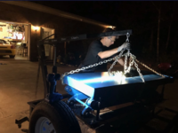
Engine hoist was perfect for lifting them off the trailer.
1679943249642.png

1679943261022.png
 

Attachments

  • 1679943177986.png
    1679943177986.png
    848.3 KB · Views: 3
Last edited:
To avoid these ads, REGISTER NOW!
OP
C

Cyclehead

Well-known member
Joined
Jan 19, 2017
Messages
85
Location
Georgia
I got everything hooked up to test in the driveway...and I have my first problem. Hitting the “up” button I can make the main or sub lift rise. But when I hit the “down” button, the motor comes on and the lifts both continue to rise! I have no way to lower the lifts.

Background: This system is different than the owners manual that came with it. The manual shows three hydraulic lines to the control panel. My system has only two lines. Owners manuals show both actuators are double-acting with a port on both sides of the pistons. My sub lift only has a port on one end so it’s single acting.
Questions: Is the pump supposed to run when I hit the “down” button? If I have the two lines to the manual “balance lever” valve reversed, could that cause the always going up behavior?
 
Last edited:

PoorOwner

Well-known member
Joined
Feb 10, 2007
Messages
5,032
Location
CA
all the lifts I have used the down button will activate a solenoid (open) and the fluid flows back by gravity and weight of the lift back to the reservoir, motor does not run.
 
OP
C

Cyclehead

Well-known member
Joined
Jan 19, 2017
Messages
85
Location
Georgia
all the lifts I have used the down button will activate a solenoid (open) and the fluid flows back by gravity and weight of the lift back to the reservoir, motor does not run.

Thanks, something is definitely odd. I may temporarily remove the 110v power to the motor and see if the solenoid is stroking to dump pressure.
 
OP
C

Cyclehead

Well-known member
Joined
Jan 19, 2017
Messages
85
Location
Georgia
Here is the hydraulic schematic of my lift. (I sketched on top of a schematic from somebody else's post.) I have no idea what happens inside the leveling valve with the question marks. I'm hoping I just have the two lines reversed at the leveling valve.

https://i.imgur.com/l6oLxNO.jpg

l6oLxNO.jpg


Last edited:

txvwnut

Well-known member
Joined
Jan 1, 2015
Messages
7,648
Location
Bedford, Texas
The schematic is wrong for a twin cylinder lift. Up should be plumbed into both bottom ports of the cylinders. In a gravity return system the top port of the cylinder(if there is one) will or should be a vent. The way they have it done in the schematic the right cylinder will always be ahead of the left unless they are using a some sort of pressure compensating circuit which is not needed.

Post pics of your setup so we can get better idea of what you have.
 
OP
C

Cyclehead

Well-known member
Joined
Jan 19, 2017
Messages
85
Location
Georgia
all the lifts I have used the down button will activate a solenoid (open) and the fluid flows back by gravity and weight of the lift back to the reservoir, motor does not run.

Finally got it! Mislabeled control panel buttons threw me off. My lift lowers when I hit the "lock" button! The "up" and "down" buttons both run the pump and raise the lifts.

I also discovered I don't have beepers or pause-before-parking features etc. I think I got the bare-bones version. It just goes up and down with no frills. My best guess is the "down" button actually does something with the fancier version of the lift but they changed out the controls in the system, and left the switches from the fancier model. (?)

 
Last edited:
OP
C

Cyclehead

Well-known member
Joined
Jan 19, 2017
Messages
85
Location
Georgia
The schematic is wrong for a twin cylinder lift. Up should be plumbed into both bottom ports of the cylinders. In a gravity return system the top port of the cylinder(if there is one) will or should be a vent. The way they have it done in the schematic the right cylinder will always be ahead of the left unless they are using a some sort of pressure compensating circuit which is not needed.

Post pics of your setup so we can get better idea of what you have.

I did a few purge cycles but probably not enough to finish the job. I'm just testing in my driveway before installing in the garage floor. My main lift always rises first, then the sub follows about 12 inches lower - even after leveling. I hope more bleeding will fix that. I'll look over the sub cylinder again for a top port. There is definitely not a hydraulic attachment there. Maybe a vent? I'll see and grab some photos.

Wow this thing goes high! .
RwG01oH.jpg
 
Last edited:

PoorOwner

Well-known member
Joined
Feb 10, 2007
Messages
5,032
Location
CA
Finally got it! Mislabeled control panel buttons threw me off. My lift lowers when I hit the "lock" button! The "up" and "down" buttons both run the pump and raise the lifts.

I also discovered I don't have beepers or pause-before-parking features etc. I think I got the bare-bones version. It just goes up and down with no frills. My best guess is the "down" button actually does something with the fancier version of the lift but they changed out the controls in the system, and left the switches from the fancier model.

Usually the lock button does something like this
"When pressed, the lowering solenoid valve operates the hydraulic circuit to
lower the lift to engage the nearest mechanical safeties."
It may raise a little bit but it should drop down for a little longer so the pawl catches on one of the lock tooth.

You can try to swap the wires at the button if it is possible.

What is with the hydraulic oil coming out of the packaging? Did it just leaked out of the ramps?


Why don't you just install it to your floor with some wedge anchors and use it for a while before cut the concrete up so you know how wide and where exactly you want it? Just need a couple of ramps.
 
Last edited:

vavet

Well-known member
Joined
Mar 6, 2012
Messages
5,329
Location
Ashland, VA
I have a similar surface mounted lift. With mine, the down button turns on the pump for 2 seconds. This raises the lift off the locks. Then the air valve open to release the locks, and the lift platforms comes down.

I documented every wire and connection in the control box to help me understand how it worked. The 2 second on time is controlled by. 24v ac timer. It’s adjustable. Yours is probably similar.
 

vavet

Well-known member
Joined
Mar 6, 2012
Messages
5,329
Location
Ashland, VA
I have a similar surface mounted lift. With mine, the down button turns on the pump for 2 seconds. This raises the lift off the locks. Then the air valve open to release the locks, and the lift platforms comes down.

I documented every wire and connection in the control box to help me understand how it worked. The 2 second on time is controlled by. 24v ac timer. It’s adjustable. Yours is probably similar.
 

vavet

Well-known member
Joined
Mar 6, 2012
Messages
5,329
Location
Ashland, VA
Here’s my schematic drawing. The timer is everything inside the red box.
 

Attachments

  • 94F935CC-41BD-49E0-A6ED-966D5C1F181C.jpg
    94F935CC-41BD-49E0-A6ED-966D5C1F181C.jpg
    125.2 KB · Views: 82
Last edited:
OP
C

Cyclehead

Well-known member
Joined
Jan 19, 2017
Messages
85
Location
Georgia
I have a similar surface mounted lift. With mine, the down button turns on the pump for 2 seconds. This raises the lift off the locks. Then the air valve open to release the locks, and the lift platforms comes down.

I documented every wire and connection in the control box to help me understand how it worked. The 2 second on time is controlled by. 24v ac timer. It’s adjustable. Yours is probably similar.

That is very helpful! I’ll try to confirm that’s what mine is trying to do.
 
OP
C

Cyclehead

Well-known member
Joined
Jan 19, 2017
Messages
85
Location
Georgia
...I documented every wire and connection in the control box to help me understand how it worked. The 2 second on time is controlled by. 24v ac timer. It’s adjustable. Yours is probably similar.

That’s exactly where I was headed, confounded why the “down” button would run the pump@!$!$. The schematics in the owners manual uses nonstandard symbols making for a real puzzle. I like your hand drawn solution.
 
OP
C

Cyclehead

Well-known member
Joined
Jan 19, 2017
Messages
85
Location
Georgia
The schematic is wrong for a twin cylinder lift. Up should be plumbed into both bottom ports of the cylinders. In a gravity return system the top port of the cylinder(if there is one) will or should be a vent. The way they have it done in the schematic the right cylinder will always be ahead of the left unless they are using a some sort of pressure compensating circuit which is not needed.

Post pics of your setup so we can get better idea of what you have.

I verified the sub cylinder only has a pressure port at the bottom - no vent or other port I can find above the piston. Pictures of all the attachments and ports!

Top of the main cylinder (above the piston)


Bottom of the main cylinder (below the piston)


Bottom of the sub cylinder (below the piston)


Top of the sub cylinder (above the piston)


Manual balance valve in the cabinet (the only two threaded ports in the whole cabinet)


Last edited:
OP
C

Cyclehead

Well-known member
Joined
Jan 19, 2017
Messages
85
Location
Georgia
Laying out overly large PVC for the subterranean hydraulic lines.

PVC pipe layout.jpg
 
Last edited:

vavet

Well-known member
Joined
Mar 6, 2012
Messages
5,329
Location
Ashland, VA
That’s exactly where I was headed, confounded why the “down” button would run the pump@!$!$. The schematics in the owners manual uses nonstandard symbols making for a real puzzle. I like your hand drawn solution.

I recommend you trace the current flow with colored pencils or different colored pens to help visualize how the current flow when each of the buttons are pressed, the fact that current flows that direction through the timer blew my mind, but once you see it colorized, it makes perfect sense.

I really wanted the current to go from terminal 1 to either 3 or 4 and from terminal 8 to wither 5 or 6. As you can see, sometimes it flows from 3 to 1 to 8 to 6.

Once you understand how it works, if you don’t like it, you can change it. I’d like to, but I’ve been busy with other things.
 

banging away

Member
Joined
Nov 9, 2018
Messages
21
Location
nh
A thought before you pour your concrete: might you need a sump pump?
Depending on your local water table might your lift hole fill with water?

When I was little my father built a garage with a pit. It was generally
filled with water and he could never use it. The water table was just too
high. For me as a kid it was great fun to play with!
 
OP
C

Cyclehead

Well-known member
Joined
Jan 19, 2017
Messages
85
Location
Georgia
I recommend you trace the current flow with colored pencils...Once you understand how it works, if you don’t like it, you can change it. I’d like to, but I’ve been busy with other things.

I’ll leave it alone for now, I was just freaking out when I thought I had no way to lower! But I’ll definitely be adding a set of remote switches on a coiled cord. And maybe a hard switch instead of temporary switch for lowering. I can’t see any real safety reason to stand at the control box the whole time the lift is lowering. My college gas station job had the in-floor hydraulic lift that would latch in the down position. (Actually it had a piece of coat hangar to hold the lever in “down” position.)

A thought before you pour your concrete: might you need a sump pump?
Depending on your local water table might your lift hole fill with water?...

Thanks for the caution - prior to pouring! I think I’m okay.
 
OP
C

Cyclehead

Well-known member
Joined
Jan 19, 2017
Messages
85
Location
Georgia
Usually the lock button does something like this
"When pressed, the lowering solenoid valve operates the hydraulic circuit to
lower the lift to engage the nearest mechanical safeties."

What is with the hydraulic oil coming out of the packaging? Did it just leaked out of the ramps?...

Thanks for explanation of “lock”, I was starting to think that buttons were mis-labeled.

The oil leakage seemed to be residual oil in the reservoir that leaked through the filler cap after I loaded the control box face-down, but slightly sloping forward. I should have had it loaded standing up!
 

jtbinvalrico

Well-known member
Joined
Jan 2, 2010
Messages
1,375
Location
Tampa FL
I can’t see any real safety reason to stand at the control box the whole time the lift is lowering.
I can't tell if you've got your limit switches set up or not, but that can definitely affect the lowering behavior....That switch should serve to stop the lowering a few inches above grade so you can make sure the extensions are retracted before lowering the platform the rest of the way into the pit.

Lowering a car on which you pulled out the extensions would require you to let the wheels of the car hit the floor, lower the platform a bit further, manually push the extensions back in, then complete the lowering cycle.

Sent from my SM-G960U using Tapatalk
 
To avoid these ads, REGISTER NOW!
Top Bottom