aunsafe2015
Well-known member
I want to install a digital timer switch on all of my bathroom fans. Something like this: https://www.amazon.com/dp/B00DF75IVG/?tag=atomicindus08-20. This particular switch model requires hot, load, neutral, and ground, although apparently they make switch models that do not require a neutral.
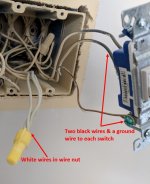
I've attached a picture of the wiring to my existing switch (which is just a standard toggle switch). It has two black wires (presumably hot and load) and a ground wire. Stuffed into the electrical box are several white wires (presumably neutral) tied together with a wire nut.
My question is this: How do I determine which of the white wires to connect to the digital timer switch? It will be simple enough for me to connect the hot, load, and ground, but there are three or four white wires in that wire nut.
Will all of them work so it simply doesn't matter which one I choose? Trial and error? Test them with a multimeter?
BTW, here's the example of the switch that does not require a neutral: https://www.homedepot.com/p/GE-In-Wall-Digital-Countdown-Timer-15318/202788262. It would obviously eliminate my issue of which neutral wire to use, but somehow I'm under the impression that the switch that requires the neutral wire is preferable if you have a neutral wire available, which I apparently do...
Thanks for any input!
I've attached a picture of the wiring to my existing switch (which is just a standard toggle switch). It has two black wires (presumably hot and load) and a ground wire. Stuffed into the electrical box are several white wires (presumably neutral) tied together with a wire nut.
My question is this: How do I determine which of the white wires to connect to the digital timer switch? It will be simple enough for me to connect the hot, load, and ground, but there are three or four white wires in that wire nut.
Will all of them work so it simply doesn't matter which one I choose? Trial and error? Test them with a multimeter?
BTW, here's the example of the switch that does not require a neutral: https://www.homedepot.com/p/GE-In-Wall-Digital-Countdown-Timer-15318/202788262. It would obviously eliminate my issue of which neutral wire to use, but somehow I'm under the impression that the switch that requires the neutral wire is preferable if you have a neutral wire available, which I apparently do...
Thanks for any input!