To avoid these ads, REGISTER NOW!

ZMotorsports Shop Projects 2.0

OP
Z

zmotorsports

ALLIANCE MEMBER
Joined
Oct 20, 2009
Messages
21,450
Location
Northern Utah
Nice work on the Case repair Mike. Done a few of those myself just like that. More Oil Pans than Crankcases for me.

Congrats on the Pan Brake!!! DiAcro is the best in my opinion. Wise choice.

Thank you Pat. That was my take on the DiAcro as well after much research. Also thanks to some people on here that answered some of my questions over the years. I'm anxious to get it in my possession, build a stand and start using it and learn on it. I'm excited for the opportunities it just opened up for various projects.

Thanks for stopping by Pat.
 
Last edited:
To avoid these ads, REGISTER NOW!

4 FN 27

ALLIANCE MEMBER
Joined
Oct 19, 2015
Messages
4,635
Location
Minnesnowta
Thank you Pat. That was my take on the DiAcro as well after much research. Also thanks to some people on here that answered some of my questions over the years. I'm anxious to get it in my possession, build a stand and start using it and learn on it. I'm excited for the opportunities it just opened up for various projects.

Thanks for stopping by Pat.

Mike let me know if you need help in figuring Bend Deductions, Bend Allowances or Set-Backs...I have lots of Educational Forming Tools I send out to our customers mostly geared around Press Brakes. But the concepts can apply to Pan Brakes too.

I will need to sort out where to move the Bend Line. Been a long-long time since I used a Pan Brake. I am going to assume the Bend Line would be the theoretical start of the Radius???

I assume you will be looking to hold +/-.005 across multiple bends???:lol_hitti

Like this part: +/-.010 between holes...

attachment.php
 

Attachments

  • IMG_8492.jpg
    IMG_8492.jpg
    111.6 KB · Views: 1,233
OP
Z

zmotorsports

ALLIANCE MEMBER
Joined
Oct 20, 2009
Messages
21,450
Location
Northern Utah
Mike let me know if you need help in figuring Bend Deductions, Bend Allowances or Set-Backs...I have lots of Educational Forming Tools I send out to our customers mostly geared around Press Brakes. But the concepts can apply to Pan Brakes too.

I will need to sort out where to move the Bend Line. Been a long-long time since I used a Pan Brake. I am going to assume the Bend Line would be the theoretical start of the Radius???

I assume you will be looking to hold +/-.005 across multiple bends???:lol_hitti

Like this part: +/-.010 between holes...


Holy **** Pat. I don't know if I'll be able to hold those tolerances or not, my guess is not.:lol_hitti

Again, this is all a learning curve for me. I figured I would start out like I did with my tubing bender. Make some test bends and then use them to design the future bends based on needed radius and go from there.
 

4 FN 27

ALLIANCE MEMBER
Joined
Oct 19, 2015
Messages
4,635
Location
Minnesnowta
Holy **** Pat. I don't know if I'll be able to hold those tolerances or not, my guess is not.:lol_hitti

Again, this is all a learning curve for me. I figured I would start out like I did with my tubing bender. Make some test bends and then use them to design the future bends based on needed radius and go from there.

Good plan Mike!!!

I would take 2 x 4 Coupons and scribe a line at 1.000 inch parallel to the 4 inch side and looking straight down at the edge of the tool align the scribe with the edge of the tool.

Make a 90° Bend and measure the length of the "Clamped" side first. Then add the other side and see how much is grew by subtracting the original flat size.

Now knowing the "Clamped" side Bend Line was at 1.000 inch you should be able to determine where the Bend would need to start if you wanted a 1.000 inch Outside to Outside (OS-OS).

Repeat again moving the Bend Line closer to the "Clamped" Edge by the amount determined. Measure again and you should be real close to a 1.000 OS_OS measurement.

You can double check the "Growth" by adding the 2 Flange Lengths and subtracting the overall flat length again.

My assumption would be the Growth will be close to @ 1/32 Inside Bend Radius:

.031 THK CRS = .059

.036 THK CRS = .062

.048 THK CRS = .080

.060 THK CRS = .095

Or @ 1/16 Inside Bend Radius:

.031 THK CRS = .072

.036 THK CRS = .075

.048 THK CRS = .093

.060 THK CRS = .108

The Growth will be the amount you want to subtract per bend from any flat layout out. The Growth is the Bend Deduction.

Not sure if the Inside Bend Radii will be effected by thickness and "springing" taking place in the Tooling/Brake??? There will be some deflection the thicker you go. How much is the question. I would be really interested in what the Material thickness effect is on the Inside Radius.

Once you get this all sorted out I am sure you can hold +/-.020 all day long. You definitely have the skill set and mechanically ability to make it happen.
 
OP
Z

zmotorsports

ALLIANCE MEMBER
Joined
Oct 20, 2009
Messages
21,450
Location
Northern Utah
That is awesome information Pat.

That is exactly the kind of experimenting I was going to do to see where I needed to start my bends to achieve either inside or outside dimensions and hold them to some kind of consistency. Even though I won't be doing production work and will be doing one-off pieces I still want to be able to hold a certain dimension if I am trying to build say a 4" outside to outside box.

Thank you very much my friend.
 

ttpete

Well-known member
Joined
Mar 8, 2011
Messages
6,737
Location
Dearborn, MI
Thank you Pat. That was my take on the DiAcro as well after much research. Also thanks to some people on here that answered some of my questions over the years. I'm anxious to get it in my possession, build a stand and start using it and learn on it. I'm excited for the opportunities it just opened up for various projects.

Thanks for stopping by Pat.

Have you ever used a Di-Acro bender? We had a big #3 in the shop, and it would do everything if set up properly.
 
OP
Z

zmotorsports

ALLIANCE MEMBER
Joined
Oct 20, 2009
Messages
21,450
Location
Northern Utah
Have you ever used a Di-Acro bender? We had a big #3 in the shop, and it would do everything if set up properly.

Not a DiAcro per se. But I've used other pan brakes before.

FYI, the DiAcro I'm referrning to is their 24" finger (pan) brake, not the #3 that you are referring to.
 

joe49

Well-known member
Joined
Sep 25, 2009
Messages
1,883
Location
Tonica, Il
Kevin, sorry for the delayed response. The Formax product that I’ve been using is their green wheel wax/grease part # R-200. It is stated as wheel wax but has a bit higher melting point than their general purpose F-26. I feel it doesn’t clog as easily.

I use it mainly on rotary burrs when grinding aluminum but have also used it on my belt and disk sander with non-ferrous materials.

If you didn't know, you could just use the correct burrs for aluminum without lubes adding to contamination.
4295a31p2-a05b-@1x_637087197629112680.png

https://www.mcmaster.com/die-grinder-bits
 
OP
Z

zmotorsports

ALLIANCE MEMBER
Joined
Oct 20, 2009
Messages
21,450
Location
Northern Utah
If you didn't know, you could just use the correct burrs for aluminum without lubes adding to contamination.

Agreed. However, like I mentioned that the aluminum burrs are much more aggressive and when trying to be a bit more delicate about it the less aggressive burrs do a better job. I have all sorts of burrs and they each serve a purpose so it wasn't a matter of not having the course burrs.
 

Opa

Well-known member
Joined
Oct 24, 2011
Messages
99
Location
placerville, ca
mike, just wanted to thank you for your videos. i learn from many of them, such as the motorcycle casing repair. i didn't know about using lube with burrs on aluminum, so thanks. also, didn't know you could heat up the aluminum casing and make the plug cold....was wondering if the cold plug into the hot casing would cause problems (eg cracking), but apparently not a problem. thanks again.
 
OP
Z

zmotorsports

ALLIANCE MEMBER
Joined
Oct 20, 2009
Messages
21,450
Location
Northern Utah
mike, just wanted to thank you for your videos. i learn from many of them, such as the motorcycle casing repair. i didn't know about using lube with burrs on aluminum, so thanks. also, didn't know you could heat up the aluminum casing and make the plug cold....was wondering if the cold plug into the hot casing would cause problems (eg cracking), but apparently not a problem. thanks again.

Thank you. I appreciate the comments and I appreciate you taking the time to watch my videos. I'm glad you enjoy them. I'll try to keep them coming.
 

shortykorte

Well-known member
Joined
Sep 1, 2014
Messages
8,039
Location
Tallahassee, Fl
Maybe something like my new toy. bef3e6a1e3a54e8d4a7eea37deebe334.jpg


Shorty Korte
Always remember quality in QST

Sent from my iPhone using Garage Journal
 

Attachments

  • bef3e6a1e3a54e8d4a7eea37deebe334.jpg
    bef3e6a1e3a54e8d4a7eea37deebe334.jpg
    52.4 KB · Views: 0

MP&C

Well-known member
Joined
Oct 21, 2009
Messages
4,405
Location
Leonardtown, MD
Mike, I've owned both the 12" and 24" in those box and pans, picked up at local school auctions. The good thing about Diacro is the quality, I never lost money on those when I sold to upgrade to a larger brake. I'd also suggest keeping your eye out on Racing Junk. That's where I picked up the first manual press brake for 250... a steal..


HPIM6458.jpg
 
OP
Z

zmotorsports

ALLIANCE MEMBER
Joined
Oct 20, 2009
Messages
21,450
Location
Northern Utah
Mike, I've owned both the 12" and 24" in those box and pans, picked up at local school auctions. The good thing about Diacro is the quality, I never lost money on those when I sold to upgrade to a larger brake. I'd also suggest keeping your eye out on Racing Junk. That's where I picked up the first manual press brake for 250... a steal..

Thanks for the information Robert. I hope not to need anything larger than this 24" but if I ever do decide to go larger I'll keep that in mind.

Thank you.
 
OP
Z

zmotorsports

ALLIANCE MEMBER
Joined
Oct 20, 2009
Messages
21,450
Location
Northern Utah
Nothing real earth shattering took place in the shop over the weekend. The weather was so nice the wife and I were able to sit on the deck and relax as well as did a fair amount of grilling.

Yesterday I did go out into the shop for about an hour while we were waiting for our son and DIL.

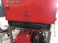
I have wanted to find somewhere else to put my SAE and Metric HSS tap & die sets that were easier to access so I quickly fabricated a couple of risers for my machining toolbox that resides on the same cart as my surface plate.

554e52ef0a987b09b568e28ecced76e0.jpg

aadc66a4866858233d0ced6821d21d69.jpg

The 4” risers created enough space to easily store the two tap & die sets under the toolbox.
 

Attachments

  • 554e52ef0a987b09b568e28ecced76e0.jpg
    554e52ef0a987b09b568e28ecced76e0.jpg
    95.9 KB · Views: 2
  • aadc66a4866858233d0ced6821d21d69.jpg
    aadc66a4866858233d0ced6821d21d69.jpg
    64 KB · Views: 2
Last edited:
To avoid these ads, REGISTER NOW!

Rag Roc

ALLIANCE MEMBER
Joined
Mar 11, 2011
Messages
297
Location
Central Florida
Nice use of space Mike. I have found toolbox risers are real handy for rollcab and workbench use as well. Nothing worse then being mid-project with parts, tools, measuring devices, etc in front of the box, and being unable to get the bottom drawer open.
 
OP
Z

zmotorsports

ALLIANCE MEMBER
Joined
Oct 20, 2009
Messages
21,450
Location
Northern Utah
Nice use of space Mike. I have found toolbox risers are real handy for rollcab and workbench use as well. Nothing worse then being mid-project with parts, tools, measuring devices, etc in front of the box, and being unable to get the bottom drawer open.

Thank you.

My problems was that when I needed to get to my pin gauges I would have to pull my tap & die sets out and usually set them on a workbench that then took up space on that workbench that could be used for something productive. Now I can get to my pin gauges easily when needed and/or get to either set of tap & dies without moving half the shop around.:lol_hitti
 

OutlawDrifter

Well-known member
Joined
Jan 20, 2015
Messages
3,895
Location
KS
Thank you.

My problems was that when I needed to get to my pin gauges I would have to pull my tap & die sets out and usually set them on a workbench that then took up space on that workbench that could be used for something productive. Now I can get to my pin gauges easily when needed and/or get to either set of tap & dies without moving half the shop around.:lol_hitti

I thought that was how it worked...? :headscrat

Move non-required items to another location that is in the way, gaining the access required to tool/thing you are looking for, instantly losing the paper/tool/pen you had in your hand at the beginning of realizing you needed new tool/thing...repeat...:lol_hitti
 
OP
Z

zmotorsports

ALLIANCE MEMBER
Joined
Oct 20, 2009
Messages
21,450
Location
Northern Utah
I thought that was how it worked...? :headscrat

Move non-required items to another location that is in the way, gaining the access required to tool/thing you are looking for, instantly losing the paper/tool/pen you had in your hand at the beginning of realizing you needed new tool/thing...repeat...:lol_hitti

I guess that's what I'm trying to change Marc. Only took me about 30 years to figure that out though.:lol_hitti
 

shortykorte

Well-known member
Joined
Sep 1, 2014
Messages
8,039
Location
Tallahassee, Fl
Shorty, that looks exactly like the one I just bought.


Have you had a chance to use yours yet? How do you like it?


So far, I’ve only used it once for a small simple project. Heavy little b@27$@4d but that’s a good thing. It’s not bolted down yet.
So far I like it and works as expected. Learning the adjustments. I will definitely print out Pat’s instructions on figuring out the bends.


Shorty Korte
Always remember quality in QST

Sent from my iPhone using Garage Journal
 
OP
Z

zmotorsports

ALLIANCE MEMBER
Joined
Oct 20, 2009
Messages
21,450
Location
Northern Utah
Tonight’s project consisted of putting my right rear door of my Jeep back together before mowing the lawn.

Friday night the wife and I went and picked up groceries and the right rear door wouldn’t unlock.
Saturday morning I tore the panel off to diagnose and determined that the motor/servo in the door lock mechanism had failed.

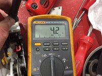
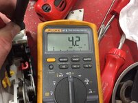
I didn’t have the resistance spec’s but when I measured the circuit it was open so that’s definitely not correct. Being a motor I would think it would be relatively low resistance so I called my local dealership. They didn’t have one but said they could have one early Monday so rather than put everything back together I just left it apart and picked up the new locking mechanism today on my lunch hour. After work I reassembled it.

Original shows open.
48c66864d4e81e3445d551719b86149a.jpg

New one displays 4.2 ohms.
4348d06e9aa5dc845b25de9d118279f5.jpg

4f7bb84d1ba3ca13c906d4f43788a329.jpg

Inner door panel installed.
320cb206cf630684bccd03d9ee480519.jpg

Window lowered and clipped back into position.
92c1a2ed851dea50e947763119d043c0.jpg

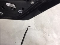
For anyone who ever has to remove one of these inner panels, you have to cut the two vertical oval cutouts shown in the picture. They’re already scored so they cut fairly easy with a utility knife. Then grab a pick or I used a cotter pin tool.
da8c65a556f3c6f862c167bb048bb596.jpg

It’s hard to see in the picture but just inside of each of the holes you just cut out, there is a clip in each you gently push inward on and it releases the glass. Then raise the glass up in the channel and tape it out of the way and finish removing the panel. Installation is just the opposite and let the window lock back into position.
eb60584f1aa5451fd3d5efc1c735e84f.jpg

Completed.
0f380912cbabccd2cace0bdbc275bd64.jpg
 

Attachments

  • da8c65a556f3c6f862c167bb048bb596.jpg
    da8c65a556f3c6f862c167bb048bb596.jpg
    55.6 KB · Views: 2
  • eb60584f1aa5451fd3d5efc1c735e84f.jpg
    eb60584f1aa5451fd3d5efc1c735e84f.jpg
    69.9 KB · Views: 1
  • 0f380912cbabccd2cace0bdbc275bd64.jpg
    0f380912cbabccd2cace0bdbc275bd64.jpg
    72.3 KB · Views: 1
  • 92c1a2ed851dea50e947763119d043c0.jpg
    92c1a2ed851dea50e947763119d043c0.jpg
    91 KB · Views: 1
  • 320cb206cf630684bccd03d9ee480519.jpg
    320cb206cf630684bccd03d9ee480519.jpg
    97.3 KB · Views: 0
  • 4f7bb84d1ba3ca13c906d4f43788a329.jpg
    4f7bb84d1ba3ca13c906d4f43788a329.jpg
    103.2 KB · Views: 0
  • 48c66864d4e81e3445d551719b86149a.jpg
    48c66864d4e81e3445d551719b86149a.jpg
    94 KB · Views: 0
  • 4348d06e9aa5dc845b25de9d118279f5.jpg
    4348d06e9aa5dc845b25de9d118279f5.jpg
    104.3 KB · Views: 0
Last edited:

customh

Well-known member
Joined
Feb 18, 2013
Messages
562
Location
East Bethel, MN
You've blown my mind. My mobile workbench at work will be getting the same treatment so I can lose things under the slant front box.
 

C_F

ALLIANCE MEMBER
Joined
Jan 21, 2005
Messages
9,675
Location
Utah...SNOW BLOWS!
The clips to release the door glass is a really cool feature! I need to replace the window regulator soon, in my significant other's driver door on her '06 Expedition, and I'm kinda dreading it. It would be great if that one has nifty glass release tabs, to make life a tad easier...but I'm not holding my breath.
The regulator assembly takes up almost as much real estate as the door itself, with lots of plastic & cables, so I am NOT looking forward to the swap. I plan to pick a nice sunny day with no other distractions, to do the deed. :D

One thing I really love about these newer vehicles is how easily the inner door panels are removed...versus 60's & 70's vehicles. Many of them have only 2-3 fasteners to remove, then you just lift the thing out of a few slots & you are in the money! Really cool.

Maybe something like my new toy. bef3e6a1e3a54e8d4a7eea37deebe334.jpg
That looks just like the one I used umpteen-times in my high school metals class! Man, I loved that thing. :thumbup:

Like this part: +/-.010 between holes...

attachment.php
Good grief, that is an impressive bunch of stacks of bent **** (sheet) metal! :bowdown: :drool:
Lemme guess...special ordered hurricane ties with a certain amount of flex built in to make the roof into a aero-foil of sorts? :lol:
 

Attachments

  • bef3e6a1e3a54e8d4a7eea37deebe334.jpg
    bef3e6a1e3a54e8d4a7eea37deebe334.jpg
    50.2 KB · Views: 0
OP
Z

zmotorsports

ALLIANCE MEMBER
Joined
Oct 20, 2009
Messages
21,450
Location
Northern Utah
You've blown my mind. My mobile workbench at work will be getting the same treatment so I can lose things under the slant front box.

Thanks Travis. I just don't know why I didn't do that little mod to my cart sooner. It's nice now to be able to just slide the tap & die set out when needed. Although I don't use my HSS tap & die sets as much as my old set that is in the toolbox drawers next to the lathe I still hated to have to move them every time I wanted to get either my Fireball magnetic blocks out or my pin gage sets.

Thanks for stopping by and checking things out Travis. Hope all is well with you and your family my friend.
 
OP
Z

zmotorsports

ALLIANCE MEMBER
Joined
Oct 20, 2009
Messages
21,450
Location
Northern Utah
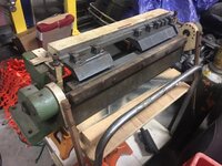
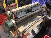
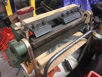
I also forgot to mention that my new to me DiAcro 24" finger brake arrived yesterday. My son stopped by the shop after work and he helped me lift it out of the truck and onto the motorcycle lift so we could play with heights to determine a good working height for the two of us. Next I will start to build a stand and then maybe I'll post up some pictures of it. I'm pleased with the unit so far and it appears to be in very nice condition, exactly what the guy told me it was and no BS from the seller.
 

gorilla

Well-known member
Joined
Dec 13, 2007
Messages
1,656
The factory stand for that Di Acro brake is 331/4" high, 15" deep and 38" wide.That machine is top heavy so if you want to put it on wheels you need to make the stand much deeper that the stock one. I had 4 of them in my shop at work no one complained about the height. We used them mostly to make tooling springs from thin 17-7 SST we could hold .005" repeatability no problem but you do need the back gage. It's worth the time to check out some of the special fingers that DI ACRO has available for that machine.
 
OP
Z

zmotorsports

ALLIANCE MEMBER
Joined
Oct 20, 2009
Messages
21,450
Location
Northern Utah
I started on my stand for my DiAcro 24” finger brake tonight. I probably could have gotten more done on the stand but had an unexpected visitor as I was driving home. More on that topic later as it was kind of a cool story.

As I dug through my metal rack I was trying to come up with a design that would also use material that I had on hand. I think this should work.

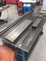
Most of the material cut to length.
d658987ac29e5dd144821d732e742cc0.jpg

The 2” x 3” tubing will be the base and there will be two 2” square vertical tubes for the legs. 1.5” angle iron front to rear will be drilled to accept the 4.75” bolt pattern of the brake.
8ed21dd8192e50d23acc4583e3d1b7c4.jpg

Drilling and tapping for the leveling feet.
83ecf43de15099e45fd0ec036dd11727.jpg

These pieces will become the leveling feet.
5f19455bd54729f9a79f66fd0935a047.jpg

Thanks for looking.
 

Attachments

  • 8ed21dd8192e50d23acc4583e3d1b7c4.jpg
    8ed21dd8192e50d23acc4583e3d1b7c4.jpg
    115 KB · Views: 0
  • d658987ac29e5dd144821d732e742cc0.jpg
    d658987ac29e5dd144821d732e742cc0.jpg
    100.8 KB · Views: 0
  • 83ecf43de15099e45fd0ec036dd11727.jpg
    83ecf43de15099e45fd0ec036dd11727.jpg
    80.8 KB · Views: 0
  • 5f19455bd54729f9a79f66fd0935a047.jpg
    5f19455bd54729f9a79f66fd0935a047.jpg
    130.4 KB · Views: 0
Last edited:
OP
Z

zmotorsports

ALLIANCE MEMBER
Joined
Oct 20, 2009
Messages
21,450
Location
Northern Utah
The factory stand for that Di Acro brake is 331/4" high, 15" deep and 38" wide.That machine is top heavy so if you want to put it on wheels you need to make the stand much deeper that the stock one. I had 4 of them in my shop at work no one complained about the height. We used them mostly to make tooling springs from thin 17-7 SST we could hold .005" repeatability no problem but you do need the back gage. It's worth the time to check out some of the special fingers that DI ACRO has available for that machine.

Thanks.

It won't be on casters as it will be mounted on leveling feet.

Thanks for the spec's, mine will be close to those dimensions but not exact.
 

lilscorpion

Well-known member
Joined
Mar 15, 2010
Messages
3,600
Location
Colorado
Thank you. The tap guide works well for keeping the threads going in true and square to the work.


Thanks for checking out the projects.


Mike, maybe you’ve commented before but why don’t you power tap on your mill? By setting up your first part and then setting a stop on your vise, you could drill all holes, switch to a tap, and then re-insert all parts and power tap. Hand tapping holes that size isn’t difficult but power tapping parts like you showed above is effortless and perfect.
 
Last edited:
To avoid these ads, REGISTER NOW!
Top Bottom