
You are using an out of date browser. It may not display this or other websites correctly.
You should upgrade or use an alternative browser.
You should upgrade or use an alternative browser.
Between 265 & 485 SQ/FT New 20 x 20 garage/shop in Seattle
- Thread starter RSwannabe
- Start date
Workspaces sized between 265 and 485 squarefeet.
Syborg - Thank you!
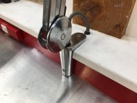
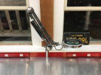
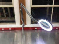
So a while ago my wife and daughter gave me an articulating magnifying lamp for the shop. I finally got around to installing it, but of course I couldn't leave it stock or mount it the way it was supposed to be. I wanted it located at the seated portion of my bench where I tend to solder and do other fiddly work and to mount it at the back of the bench so it could fold out of the way when not in use.
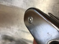
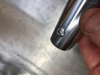
The lamp came with a C-clamp mount designed to be attached to the edge of a table or desk. As there was no edge at the rear of the bench to clamp it to, I had to modify it to suite my situation. I cut the lower return leg of the C-clamp off and then machined two recessed bolt holes into the body of the mount. I turned down the heads of two large stainless square drive metal screws to fit into the recessed mounting holes and polished the heads to match the mount. I then cut a relief into the backsplash behind the bench and bolted it into the wood structure there.
So a while ago my wife and daughter gave me an articulating magnifying lamp for the shop. I finally got around to installing it, but of course I couldn't leave it stock or mount it the way it was supposed to be. I wanted it located at the seated portion of my bench where I tend to solder and do other fiddly work and to mount it at the back of the bench so it could fold out of the way when not in use.
The lamp came with a C-clamp mount designed to be attached to the edge of a table or desk. As there was no edge at the rear of the bench to clamp it to, I had to modify it to suite my situation. I cut the lower return leg of the C-clamp off and then machined two recessed bolt holes into the body of the mount. I turned down the heads of two large stainless square drive metal screws to fit into the recessed mounting holes and polished the heads to match the mount. I then cut a relief into the backsplash behind the bench and bolted it into the wood structure there.
Attachments

The lamp came with a long cord with the switch half way down the cord. I wanted it to be hard wired in with a switch mounted on the body of the lamp somewhere. So I rewired it using some vintage looking cloth covered wired I have, installed a small toggle switch into the ballast housing, and ran the wiring down into the backsplach to connect into the circuit for the outlets mounted to the backsplash.
Attachments


Last edited:
Grumblebum
Well-known member
Looks great RS. I need to get one of those lamps too at some point.
GB
GB
Rich
Well-known member
I've got one of those and tried mounting it in about 10 different locations, none of which worked for what I wanted. I like your idea...way to think outside the box.
Grumble - I turn 50 this year and have needed reading glasses for close up work for a number of years. This magnifying lamp is a nice addition to my arsenal of reading glasses.
Rick - Mounting the lamp to the front edge of the bench was not an option, so I had to get creative (as usual).
Rick - Mounting the lamp to the front edge of the bench was not an option, so I had to get creative (as usual).
RSwannabe - I am really impressed by your efficient space usage, and love the aesthetic, which is so distinctly Seattle.
You mentioned that you're in commercial real estate. Do you have any leads on where to look for residential blueprints, design docs, anything else that will provide history or information on how my place was built? I live in Seattle city limits.
You mentioned that you're in commercial real estate. Do you have any leads on where to look for residential blueprints, design docs, anything else that will provide history or information on how my place was built? I live in Seattle city limits.
Mitchellc - I checked out your build thread. Am I right to assume you’re looking for plans of your townhouse? You should have no problems getting the full plan set from the Dept of Construction and Inspections (DCI). Their plans archive is located on the 20th floor of the 700 5th Ave building downtown. You can walk in and have them pull plans on record for you and either make hard copies or email PDFs. Your home is new enough they also might be online. Check here - https://web6.seattle.gov/dpd/edms/. Hope this helps.
Last edited:
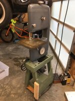
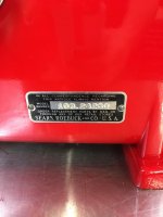
Like many of you, I've been taking the extra time at home during covid to go through my storage and get organized and clear stuff out. In doing that I had to make the call on an old Craftsman bandsaw I've had in my basement awhile. It was a 103.24260 from the '60's I picked up years ago along with a drill press for about $75. I prefer the aesthetics of the earlier style bandsaws from the '50's, and so I'd never really done anything with the saw.
I decided to keep the saw and put it in use until I could get an earlier style saw to replace it. I suspected, but was not positive, that the earlier style saws had the exact same foot size and placement. So if I built a nice stand for this saw it would also work for the earlier style as well.
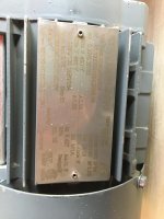
The saw did not have a base and the old motor that came with it was in very rough shape. So I decided to toss the motor and engineer a solution to give me the ability to slow the saw down for cutting metal (typically 100-300 fpm blade speed) and while also still able to cut wood at faster speeds (2,000-3,000 fpm blade speed). So I kept an eye out on Craigslist and found a guy selling a SEW Eurodrive 1/2 hp three phase gear reduction motor for a good price. The gear reduction takes the 1680 rpm motor speed and reduces it to 164 rpm (and multiplying the effective torque of the motor) for a good starting speed. Additionally, running the motor on a variable frequency drive (VFD) would allow me to plug it into 110v and have additional speed variability from 0 - 328 rpm on the shaft by running up to 120 hrz frequency. This motor, combined with 1"-4" drive pulleys on both the motor and the saw, will give me a blade speed range of sub 100 fpm up to over 4,000 fpm.
I decided to keep the saw and put it in use until I could get an earlier style saw to replace it. I suspected, but was not positive, that the earlier style saws had the exact same foot size and placement. So if I built a nice stand for this saw it would also work for the earlier style as well.
The saw did not have a base and the old motor that came with it was in very rough shape. So I decided to toss the motor and engineer a solution to give me the ability to slow the saw down for cutting metal (typically 100-300 fpm blade speed) and while also still able to cut wood at faster speeds (2,000-3,000 fpm blade speed). So I kept an eye out on Craigslist and found a guy selling a SEW Eurodrive 1/2 hp three phase gear reduction motor for a good price. The gear reduction takes the 1680 rpm motor speed and reduces it to 164 rpm (and multiplying the effective torque of the motor) for a good starting speed. Additionally, running the motor on a variable frequency drive (VFD) would allow me to plug it into 110v and have additional speed variability from 0 - 328 rpm on the shaft by running up to 120 hrz frequency. This motor, combined with 1"-4" drive pulleys on both the motor and the saw, will give me a blade speed range of sub 100 fpm up to over 4,000 fpm.
Attachments

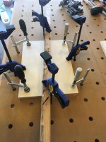
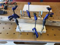
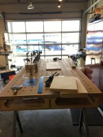
With the motor in hand, I then drew up my plan for a compact and good looking base unit for the saw. I picked up a 5'x5'x3/4" sheet of Baltic birch plywood for its high lamination count and low void construction. It will make for a very strong and dimensionally stable base. I ripped part of it into 7" wide strips and glued 6 of those together to make 7" wide and 4.5" think legs.
I glued two layers together for a 1.5" think top plate and 4 of them them together for a 3" thick bottom plate. Since my folks are out of town during this time I set up my Paulk bench in my dad's shop for the extra room for this work.
I glued two layers together for a 1.5" think top plate and 4 of them them together for a 3" thick bottom plate. Since my folks are out of town during this time I set up my Paulk bench in my dad's shop for the extra room for this work.
Attachments

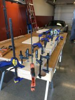
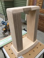
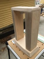
I then trimmed and shaped the pieces of the base to compliment the general shape of the bandsaw and glued and screwed them together. With the base assembled, I was able to mount the motor and saw and check the speeds and torque. Using a bimetal blade it can cut 1/2" mild steel plate relatively easily, if not particularly quickly. It can move through thinner and softer materials cleanly and quickly.
Attachments


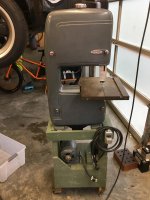
It was right at this point in the project that my craigslist search turned up a good condition earlier model of the bandsaw (model 103.24280) local to me for $125. I went and inspected it and confirmed the feet size and locations were identical to my old saw and thus would work with the base I built. So I picked it up, swapped my old saw onto the base/motor the new (older) saw came on, and sold it for $150 two days later. So now I had the vintage of saw I wanted and an extra $25 in my pocket.
Attachments


Last edited:
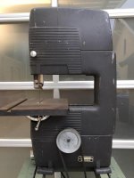
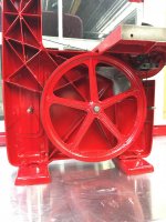
It was interesting to compare the two saws side by side. The later model saw has a boxed internal section for strength as compared to the open truss section used in the earlier saw. The later style boxed section is MUCH stiffer, and allows you to make all you tension adjustments and tracking adjustments with the side cover off the saw. The older style saw really relies on both halves of the saw being mated together for its stiffness, and thus you have to tension the blade and adjust the tracking with the saw closed up. That is OK, as the adjustments are all accessible externally. The only benefit of the older design compared to the newer model (not counting the aesthetics of the saws, where the older version wins hands down in my opinion) is that you can get more blade tension on with the manual adjustment of the older style.
Here are detail pics of the later model saw for comparison.
Here are detail pics of the later model saw for comparison.
Attachments


Even through the new saw was in very good condition, I fully disassembled it, cleaned and inspected everything, and repainted it. The bearings were in good shape and did not need replacing.
Attachments


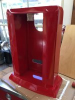
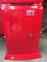
While I was restoring the saw, I was also finishing up the base. My neighbors are professional painters and gave me the dregs of a 5 gal bucket of Miller brand Acrylic Undercoat to use as a high build primer. I used this on the wood base in preparation for paint and was REALLY impressed with it. It is water soluble, can be applied in thick coats, dries fast and then sands more like an enamel. I did two rounds of priming and sanding with this before spray painting the base with Rustoleum Sunrise Red (same as the saw).
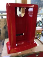
The motor is mounted to an L bracket attached to the underside of the top plate, with slotted holes so the motor may be slid up and down to tension the belt. I extended the wires for the on/off switch and speed selection dial so I could remote mount them on a separate plate and leave the VFD box inside the base. The switch panel is aluminum L bracket that I polished and then clear coated.
The motor is mounted to an L bracket attached to the underside of the top plate, with slotted holes so the motor may be slid up and down to tension the belt. I extended the wires for the on/off switch and speed selection dial so I could remote mount them on a separate plate and leave the VFD box inside the base. The switch panel is aluminum L bracket that I polished and then clear coated.
Attachments


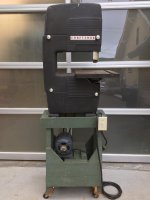
And here is the saw mounted on the base. It is now fully functional and ready to be used, but I still need to finish the front cabinet door for the base, which will be on hinges to allow easy access and storage of spare blades in the base.
Attachments


Jeff Ivers
Well-known member
Beautiful job on that saw and stand!
Arclitgold
Well-known member
- Joined
- Dec 20, 2017
- Messages
- 317
Wow! That is some amazing work. That stand is as smooth as it could be! If I didn’t know better I’d think it was metal
Sent from my iPhone using Tapatalk
Sent from my iPhone using Tapatalk
smschriefer
Well-known member
That came out beautifully. I like the detail you put on the base by incorporating a spare tension knob from the band saw.
ODIS
Well-known member
Have always enjoyed this thread. Everything so nicely done and great attention to detail. Really like the base to your band saw and if you had not shown your build process, would have never believed it was “home made” from plywood. Beautiful!
Well, I haven't posted for a while. For the last year plus I have been rebuilding a 1916 Craftsman home in Seattle. This was a full time work project on which I self performed almost all aspects. While some might call it a house flip, it was more accurately a restomod with all systems and components updated and modernized while keeping the Craftsman aesthetic and charm. It took all my time and most of my "project creativity" bandwidth. I'm scheduled to close sale of that house this week, so I am now able to get back to some of the projects I post here.
A page back I posted about the Emco Maximat 7 lathe and mill I acquired. I really liked the lathe and mill and was enjoying using it for various projects. However, I was hoping for something a little larger and had a search on craigslist. That search turned up an Emco V10P less than a mile from my house. I snapped it up within an hour of being posted. The V10P is a slightly larger lathe with a 10" swing and 25" working length. Even better is the V10P has a threading gearbox (mine is imperial) and a power cross slid that the Maximat 7 lacks. My V10P also came with the mill attachment, a nice Bison 3 jaw chuck, and various other components.
The seller was able to load it into the back of a pickup with their forklift. I was able to unload it by unbolting one of my toolboxes from my workbench island and use it as a rolling cart to move the lathe into the garage.
Last edited:
My V10P was the Mentor version that was intended to be a teaching lathe. That means it came on its own stand and the electrical control switches were mounted on the stand instead of on the headstock of the lathe. The headstock mounted switches on these lathes are known to be problematic and difficult to replace if they fail. The switches on the mentor are a different design and much more robust, so this is a plus. I tried making room for the lathe stand as well, but after trying a few different configurations, i decided to sell off the base and put the V10 on the workbench I had made for the Maximat 7. It is just a far more efficient use of space in my shop. I made a box for the electrical switches and mounted them on the underside of the shelf above the lathe. It is a more convenient location with easy access to the emergency stop switch as well. I also mounted an LED light panel on the underside of the shelf above and wired it into the lathe power switch. So if the lathe is powered up, the light is on.


Last edited:
On the Maximat 7 I had fabricated a solid tool post to mount a new multifix style tool holder and replace the compound slide. This is something I had read about others doing as it eliminates an area of flex and movement by removing the compound and allows a small machine to make deeper cut in material and achieve better surface finishes. Here is the solid tool post I made for the Maximat 7.
I cut is out of a chunk of steel I had lying around using a horizontal band saw, cutting the angles faces with that bandsaw as well. I rounded the edges on a big belt sander. The upper and lower mounting surfaces were fly cut on a mill to make sure they were as flat and parallel as I could get them. The vertical post was turned on the Maximat itself (always fun to use a tool to take a tool for use on that tool). This project was my first attempt at cutting threads with the lathe and while they are not the prettiest threads, they are good enough and work great with strong clamping force. I cut the flats for the wrench with the mill head.


I cut is out of a chunk of steel I had lying around using a horizontal band saw, cutting the angles faces with that bandsaw as well. I rounded the edges on a big belt sander. The upper and lower mounting surfaces were fly cut on a mill to make sure they were as flat and parallel as I could get them. The vertical post was turned on the Maximat itself (always fun to use a tool to take a tool for use on that tool). This project was my first attempt at cutting threads with the lathe and while they are not the prettiest threads, they are good enough and work great with strong clamping force. I cut the flats for the wrench with the mill head.
In the picture of the V10P above you can see the partially finished solid tool post for that lathe sitting on the cross slide. The V10P and the Maximat 7 have different centerline heights and different cross slide T-slot widths, so I couldn't just reuse the one from the 7 on the 10. The V10P needed a taller a wider solid tool post, bigger than any piece of metal I had lying around. I could have bought a chunk off of Online Metals, but it wouldn't have been cheap for the size I needed. Luckily a local metal workers group I'm part of came through with a free 100lb chunk of 8" round of steel I could use. I formed the base the same as i did for the 7. I have stalled on making the vertical post though. I tend to work in metric, so I wanted to cut the post threads in metric. My V10P has an imperial threading box though. You can get change gears that allow it to cut metric, but they are rare and expensive. You can also fabricate or adapt the gears needed for metric cutting, which is what I've been trying to do with limited success. This is where this project stalled out while I've been working on other things (mostly the house restomod). I'll likely just redo the post in imperial thread and call it good and move on. I'll post on that when done (hopefully soon).


ODIS, I'm about a year and a half late, but thanks for the kind words.Have always enjoyed this thread. Everything so nicely done and great attention to detail. Really like the base to your band saw and if you had not shown your build process, would have never believed it was “home made” from plywood. Beautiful!
ODIS
Well-known member
Hey! No problem at all. I've the same endmill mounted to my Southbend lathe. Although, I've never used it as all of the endmill stuff goes to the Enco mill in the shop. Hope you have a great 2022 and other great years as well.ODIS, I'm about a year and a half late, but thanks for the kind words.
Odis.
Finished the solid tool post for the V10P today. 20mm diameter post for the Multifix size A quick change tool holder. I can run up to 3/4” tooling in this. The last pic shows 3/8” cutoff tool in a holder and how high it’s raised to align to centerline of the lathe. It gives me lots of options on what tools to use.
Attachments


HassB
Member
Walls are formed and getting poured today. The back wall of the garage is 9'10" high and designed to be backfilled to an elevation of 6'. Its full height concrete because there is no "heel" on the footing, thus allowing me to get the wall as close as possible to an existing hillside without disrupting the existing retaining wall. With no heel on the footing, the wall is designed to be braced at the top by the roof structure.
Hi @RSwannabe, I'm a new lurker to the Garage Journal forum, I have an idea (more than firm plans) to build my own expanded garage with a 2nd story on top. Current garage is 10w x 20L
My garage / garden layout looks very similar to yours (see diagram). My current garage has a retaining wall at the back ~4.5'. It looks like your concrete walls are not retaining in any way for the land behind as you kept the old one in place?

A couple of quick questions.
- Did you look at replacing the retaining wall at the back?
- Do you have a drawing of how close you were able to build to the existing one?
- If possible if you worked with an architect / structural engineer and you liked their work you could possibly share them. I'm also in Seattle.
I know it's probably 100x easier cheaper to have a separate retaining wall however my current garage footprint is 20' long and sits very very close to the property line and I don't have space to move forward so trying to think of options to get a shell without breaking the bank (completely).
Don't worry if nobody see's this, I will start a thread in the near future if I can afford to do what I want to do;
Well, I haven't been on here for a few years it seems and missed some messages. I apologize for the late responses.
@pickles - I sold my Gulf blue 1981 911 that was backdated with a 930 turbo drivetrain on BaT in 2019. It has since been resold to new owners on BaT in 2024 and 2026 (link - https://bringatrailer.com/listing/1981-porsche-911sc-89/), but since none of those dates correspond to your question in July '23, I'd say the answer is no, that was not my 911 for sale on BaT at that time.
@HassB - This is probably too late to be helpful, but the back wall of my garage is indeed a retaining wall. I had to cut the soil at the low side of the existing retaining wall when I built the garage. I then filled the area between my garage wall and the hillside/retaining wall with gravel after the garage structure was complete to support the hillside and old retaining wall behind the garage.
I acted as architect for my project and roped my cousin who is a structural engineer for the load calcs I needed. He is primarily a commercial work engineer and not typically handling small jobs like this.
Last edited: