To avoid these ads, REGISTER NOW!

CO detector wiring help?

ajchien

Well-known member
Joined
Sep 3, 2010
Messages
2,652
Location
Los Angeles, stuck on the 60 freeway.
Homeowner here. It was past the 10 year mark for our old CO monitor in the house. (Stuff deleted to remove confusion)
Found out the old CO monitor is an Edwards Signaling 250-CO (by interlogix). The “replacement” is a 260-CO.

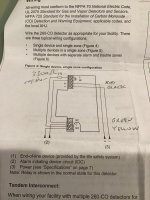
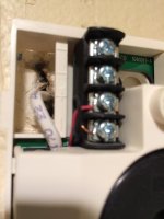
I’ve posted below the wiring diagram and pictures of the OLD wiring configuration. Note a resistor between the green and yellow wires.

When I connect the NEW 260-CO, it constantly flashes RED alarm while setting off the beeps unless I silence it. If I remove the resistor between the green and yellow wires, the LED pulses green intermittently - “working normally”.

I don’t understand the wiring diagram. Am I supposed to have this resistor in there? It looks like it should have the resistor for the end-of-Line device And this is a single unit installation ... but that the alarm constantly sounds with the resistor in there. (Looks to be a 3300ohm resistor by the colors). Tech support not open till tomorrow.

Again, Pics below are how it used to be wired. If I copy that, the alarm doesn’t stop sounding. Taking out the resistor puts it into a “normal mode”.
 

Attachments
  • 43391C0D-1006-4764-84DE-1B044AB90E25.jpg
    43391C0D-1006-4764-84DE-1B044AB90E25.jpg
    50.3 KB · Views: 43
  • 2C248098-CDF7-4AE1-B558-DA0B95C02194.jpg
    2C248098-CDF7-4AE1-B558-DA0B95C02194.jpg
    47.4 KB · Views: 43
  • C110B82D-9853-48F1-B1AD-457969E465AF.jpg
    C110B82D-9853-48F1-B1AD-457969E465AF.jpg
    103.6 KB · Views: 62
Last edited:
To avoid these ads, REGISTER NOW!

laser3kw

Well-known member
Joined
Nov 17, 2012
Messages
7,276
Location
northen IL
The posted drawing shows the resistor in line with the wiring not across the terminals. Give that a try.

the "resistor" is called an "end of line device" in the instructions. I am guessing that is for another interface, possible an outside security system.

I knew it was hardwired so I bought a kidde detector. When I went to take apart the old CO monitor, I noticed it had 12V wiring, not the 120V the kidde used.
what model are you installing? The 120v Kidde mentioned or the new Edwards signalling 260-CO (12 / 24vdc)? The instructions are from the Edward's 260-CO? Mr. Obvious states you can't run a 120v(ac) item off 12 vdc.
 
Last edited:
OP
A

ajchien

Well-known member
Joined
Sep 3, 2010
Messages
2,652
Location
Los Angeles, stuck on the 60 freeway.
I am trying to install the Edwards 260-CO, so that I can keep things as close to the same as possible.

The house is hardwired with a smoke alarm system, there is a fire bell on the outside of the house towards the street, and there are also sprinklers throughout the home.

Ok, I just read a bit about end of line devices. I’m going to have to absorb the info for a bit.

The phone number to call was kind of useless. They said they were unable to assist end users and to contact a website to find a dealer. Unfortunately, the website they sent us to was a website for people the joon to become / registrar as dealers. Not a dealer finder website. The seller of the device has a voicemail turned off, everyone is in New York. Yay Covid.
 
Last edited:

laser3kw

Well-known member
Joined
Nov 17, 2012
Messages
7,276
Location
northen IL
looking at your pictures, the first picture, is your power connection, red +12, black -12. Second picture is your "alarm" connection, green / yellow. That connection goes to the "No" normally open relay inside the unit.
the "end of line" resistor would normally be to supply the other system with a small feed back current so the other system knows the CO detector is there and the wiring is good. The diagram shows the resistor across the NC / normally closed contact inside the unit and in parallel with the "NO" contact. The second picture shows a short cut by installing it across the NO terminals effectively doing the same function for monitor current supplying.
I also don't know why the new unit would act any different than the old one. The manufacture suggested the 260-CO as the replacement.
 
Last edited:
OP
A

ajchien

Well-known member
Joined
Sep 3, 2010
Messages
2,652
Location
Los Angeles, stuck on the 60 freeway.
looking at your pictures, the first picture, is your power connection, red +12, black -12. Second picture is your "alarm" connection, green / yellow. That connection goes to the "No" normally open relay inside the unit.
the "end of line" resistor would normally be to supply the other system with a small feed back current so the other system knows the CO detector is there and the wiring is good. The diagram shows the resistor across the NC / normally closed contact inside the unit and in parallel with the "NO" contact. The second picture shows a short cut by installing it across the NO terminals effectively doing the same function for monitor current supplying.
I also don't know why the new unit would act any different than the old one. The manufacture suggested the 260-CO as the replacement.

FWIW, I know only little here, so this probably makes me dangerous.

1) The new unit, currently installed, shows continuity on the top two connectors C and NC, so I presume that little mark on the diagram means that it is normally closed. The disconnected old unit, has no continuity between those poles. I presume that powering up the unit switches a relay to close that connector.

2) power at the + / - measures 13.8v

3) power at the Alarm circuit bottom green (C) / yellow wires (NO) Measures 12.7v

4) The old resistor (Orange orange red gold - I think this is 3300ohms) you saw in the 2nd picture above connecting the green and yellow wires (which is currently NOT installed anywhere) is measuring *infinity/open*.


So I think the resistor is bad. But I still can’t figure out how the system is trying to work. In my mind, I want the system to read a reference voltage with the “end of line device resistor” in place as normal. When you say there is a normally open relay inside, does that mean closed = 12v = alarm, reference voltage = normal operation, and 0 volts means broken wire? So by putting an infinite resistor across the yellow and green wires, it seems to trigger beeping, where it might by trying to tell me broken wire? But Then if it is looking for a reference voltage, why is leaving the Bad resistor completely out causing the CO monitor to flash “green” normal operation rather than alarm? It’s just not making sense to me right now. This is supposed to be easy.

Also, by looking at what I have, is there potentially another CO detector in the house somewhere that I have not found? Two story house, this one is upstairs. I don’t see another anywhere.
 
Last edited:

laser3kw

Well-known member
Joined
Nov 17, 2012
Messages
7,276
Location
northen IL
FWIW, I know only little here, so this probably makes me dangerous.

1) The new unit, currently installed, shows continuity on the top two connectors C and NC, so I presume that little mark on the diagram means that it is normally closed. yes
The disconnected old unit, has no continuity between those poles. I presume that powering up the unit switches a relay to close that connector. not sure, not typical according to the schematic

2) power at the + / - measures 13.8v good

3) power at the Alarm circuit bottom green (C) / yellow wires (NO) Measures 12.7v good - the 12.7 is coming from the other system

4) The old resistor (Orange orange red gold - I think this is 3300ohms) you saw in the 2nd picture above connecting the green and yellow wires (which is currently NOT installed anywhere) is measuring *infinity/open*. 3300 ohm sounds right and matches color code - when measured out of circuit it measures infinity? that's not right

So I think the resistor is bad. But I still can’t figure out how the system is trying to work. In my mind, I want the system to read a reference voltage with the “end of line device resistor” in place as normal. When you say there is a normally open relay inside, does that mean closed = 12v = alarm, reference voltage = normal operation, and 0 volts means broken wire?
no, on the alarm side NO contact if you measure across the NO terminals, 12v would mean no alarm and when the unit detects CO and closes that terminal, the voltage will drop to "0" or a small voltage
So by putting an infinite resistor across the yellow and green wires, it seems to trigger beeping, where it might by trying to tell me broken wire?
the resistor should not be infinity. It should read 3300 ohm out of circuit.But Then if it is looking for a reference voltage, why is leaving the Bad resistor completely out causing the CO monitor to flash “green” normal operation rather than alarm? It’s just not making sense to me right now. This is supposed to be easy.

Also, by looking at what I have, is there potentially another CO detector in the house somewhere that I have not found? Two story house, this one is upstairs.

I am assuming that you have a "security system", which is what the CO monitor is hooked to. It would follow that there may be another CO monitor ,as well as, smoke detectors.
 
OP
A

ajchien

Well-known member
Joined
Sep 3, 2010
Messages
2,652
Location
Los Angeles, stuck on the 60 freeway.
I am assuming that you have a "security system", which is what the CO monitor is hooked to. It would follow that there may be another CO monitor ,as well as, smoke detectors.

Okay. Yes. That is potentially what’s going on and something I haven’t looked into.

When we moved in to this house, there was a pre existing alarm/security system. We had brought with us from a prior residence a “wireless” security system which we installed, upgraded, and is Working fine.

We considered the old system antique and just left it alone since we brought our current security system with us. It does say on the old system to call a phone number for service and to reactivate.

I’m going to have to dig into the back of a closet now to check out the old security system main panel more...

All of the smoke detectors are now newly replaced as of last week and hardwired into the house. The CO monitors I’m currently doing was supposed to be the last step in updating. If we have not activated the “old security system”, **** can I assume that each of the smoke detectors and CO monitors are working solo, but are not working in tandem or with the sprinkler system unless we Re-activate the old security system?

I’m also going to get an appropriate 3300 ohm resistor to replace the broken one.

(For background, the house we bought as a short sale from an “estate”. Previous owner had passed away years ago, and it had sat empty for 2+ years. When we first saw it, it had cobwebs all throughout the home. Since it was from an “estate”, no one really had any ideas of what was or wasn’t working in the home. And no hints of any documentation of anything anywhere.) BTW, thanks for all your assistance. It’s really appreciated.
 
Last edited:

laser3kw

Well-known member
Joined
Nov 17, 2012
Messages
7,276
Location
northen IL
If there are multiple devices and a security system, you may have to hook it up as the instructions show for multiple devices. adding wires from the lower alarm terminals to the upper monitor terminals with the EOL resistor as they show it. That provides a current loop for monitoring the system. If any device in the system sounds, this loop causes the others to sound. Only the device that has detected the CO will also have a flashing red light, the others will have sound only.
You will also have to investigate the entire system to make sure there is only one EOL resistor.
 

laser3kw

Well-known member
Joined
Nov 17, 2012
Messages
7,276
Location
northen IL
also, the CO detector will operate independently with out being hooked up to a system. just hook up the +12vdc and no connection to the other terminals. When it detects CO it will sound but nothing else will.
 
To avoid these ads, REGISTER NOW!
OP
A

ajchien

Well-known member
Joined
Sep 3, 2010
Messages
2,652
Location
Los Angeles, stuck on the 60 freeway.
also, the CO detector will operate independently with out being hooked up to a system. just hook up the +12vdc and no connection to the other terminals. When it detects CO it will sound but nothing else will.

Thanks. That’s very helpful and makes complete sense.

By the way, I found in a downstairs hallway up high on a wall there are two mystery wires sticking out of the wall. Red and black wires, with measured voltage 5v DC. It’s not the 4 wire system Red/black/green/yellow for the CO monitor upstairs. It resides right next to a smoke alarm and the doorbell chime. Any chance you think this could have been part of the prior alarm system?
 
Last edited:

wyliesdiesels

Well-known member
Joined
Aug 14, 2012
Messages
20,074
Location
Modesto, CA
Late to this thread but an EOL resistor for a security or fire alarm system is typically 1K Ohm and is used to allow the alarm to verify the wiring is intact.

the wire should be in series of one wire on the contact loop.
 

laser3kw

Well-known member
Joined
Nov 17, 2012
Messages
7,276
Location
northen IL
Thanks. That’s very helpful and makes complete sense.

By the way, I found in a downstairs hallway up high on a wall there are two mystery wires sticking out of the wall. Red and black wires, with measured voltage 5v DC. It’s not the 4 wire system Red/black/green/yellow for the CO monitor upstairs. It resides right next to a smoke alarm and the doorbell chime. Any chance you think this could have been part of the prior alarm system?

I would wonder why it has 5 vdc on it with no device. If the security system has been out of service for a couple of years, why was it left powered up? That is an invite for problems to leave exposed wiring with voltage on them. If it is red / black, it should have been a supplying power to something.
 

BFBOB

Well-known member
Joined
Sep 20, 2011
Messages
5,073
Late to this thread but an EOL resistor for a security or fire alarm system is typically 1K Ohm and is used to allow the alarm to verify the wiring is intact.

NO. The resistance of the EOLR varies with the brand and model of the alarm panel. Values I have encountered include 5.6K, 3.3K, 33K, 4.7K 2.2K 2K oh, yeah, and 1K.

You are correct as to the EOLR's function - as long as it is installed at the FAR end of the line, but series vs parallel depends on the function (and the panel). Burglar alarm devices are usually normally closed with the resistor in series with the contacts. Fire alarm devices are usually normally open, with the resistor in parallel with the contacts. Both conditions can coexist on one panel, with programming determining which way an individual zone works. Again, varies with brand and model.

The answer for the OP is not to overthink it, put the wires back on the terminals having the same marked function as the original.
As for the infinite resistance - that's very rare. Check your meter, make sure it can tell the difference between open circuit and dead short, make sure it's set for resistance, not continuity, and make sure it's not set to such a low resistance range that 3K looks like open (infinite).
 
Last edited:

jbwilkins

Well-known member
Joined
Mar 16, 2016
Messages
310
Location
Nashville Tn
Thanks. That’s very helpful and makes complete sense.

By the way, I found in a downstairs hallway up high on a wall there are two mystery wires sticking out of the wall. Red and black wires, with measured voltage 5v DC. It’s not the 4 wire system Red/black/green/yellow for the CO monitor upstairs. It resides right next to a smoke alarm and the doorbell chime. Any chance you think this could have been part of the prior alarm system?


Thanks. That’s very helpful and makes complete sense.

By the way, I found in a downstairs hallway up high on a wall there are two mystery wires sticking out of the wall. Red and black wires, with measured voltage 5v DC. It’s not the 4 wire system Red/black/green/yellow for the CO monitor upstairs. It resides right next to a smoke alarm and the doorbell chime. Any chance you think this could have been part of the prior alarm system?


Older doorbell systems were 5v...
 
OP
A

ajchien

Well-known member
Joined
Sep 3, 2010
Messages
2,652
Location
Los Angeles, stuck on the 60 freeway.
I would wonder why it has 5 vdc on it with no device. If the security system has been out of service for a couple of years, why was it left powered up? That is an invite for problems to leave exposed wiring with voltage on them. If it is red / black, it should have been a supplying power to something.

Im completely unsure what the wires were for. For now, I’ve capped them off. I plan to shove them in a junction box and cover. Hopefully enough to “hide” it, but accessible enough if I ever find out why it’s there. Unless you guys think that’s a bad idea and I should instead do something more drastic to disable the power.
 

yatg

Well-known member
Joined
Aug 16, 2019
Messages
2,836
Location
Southern Oregon
If you do what laser3kw said in post 10, i.e. disconnect the green and yellow wires and the EOL resistor and run the CO detector stand alone, be aware that at some point the power supply in the alarm system will die. When the power supply dies, you'll have no CO protection until you either fix it or change over to battery or 120V CO detectors.

While you're thinking about it, find how the alarm system is getting its power. There will be a transformer somewhere. Depending on the age of the alarm system, it could be an open frame or plug in block.

And there may be a backup battery in the alarm panel box that needs replacing. Without a backup battery, you'll have no CO protection during power failures.
 
OP
A

ajchien

Well-known member
Joined
Sep 3, 2010
Messages
2,652
Location
Los Angeles, stuck on the 60 freeway.
If you do what laser3kw said in post 10, i.e. disconnect the green and yellow wires and the EOL resistor and run the CO detector stand alone, be aware that at some point the power supply in the alarm system will die. When the power supply dies, you'll have no CO protection until you either fix it or change over to battery or 120V CO detectors.

While you're thinking about it, find how the alarm system is getting its power. There will be a transformer somewhere. Depending on the age of the alarm system, it could be an open frame or plug in block.

And there may be a backup battery in the alarm panel box that needs replacing. Without a backup battery, you'll have no CO protection during power failures.

Ok thanks, will be putting finding out the power source of the co monitors on the list. Right now the main alarm service panel is behind a whole boatload of my wife’s clothes in the closet.
 
To avoid these ads, REGISTER NOW!
Top Bottom