To avoid these ads, REGISTER NOW!

Montgomery Ward Table Saw Face Lift

2oolhound

Well-known member
Joined
Dec 18, 2010
Messages
5,918
Location
BC Canada
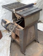
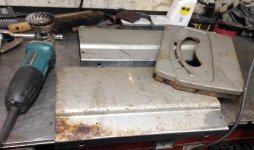
A little background info to start - One day working in my front yard an elderly gent stopped to say a few words. We ended up chatting until dark while I worked. Before he hurried home he said he really enjoyed talking to me and asked if I’d mind if he stopped to chat again if he saw me outside during one of his walks to which I told him “never mind if you you see me outside, you come right up the steps and knock on my door”. We became good friends after that as I’ve always tried to respect the old timers and when he had to move and was stressing about the cost of taking things to the dump I offered to help out. He wound up giving me a bunch of old tools, one of which was this old Montgomery Ward Table Saw.

attachment.php


attachment.php


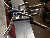
The old boy passed about 2 years ago (93 yrs old) and I had cause to pull out the old saw and try cutting steel with it using a carbide blade a week ago. When it was ready to go I found the 1/4HP. motor wouldn’t turn. A sharp whack on the end of the shaft freed it and it turned. I squirted some oil into the cups and watched it pour right through the bearings onto the ground so I replaced the motor with a 1/2 HP unit I had. The saw did a fine job cutting through 1/4” plate steel after that!

attachment.php


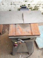
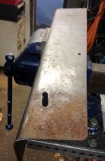
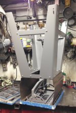
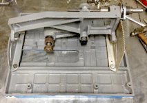
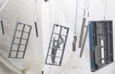
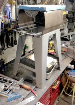
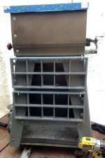
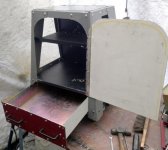
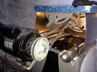
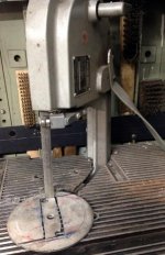
Next I did a small wood work project with it and noticed the blade wobbled side to side especially when it was raised up for deep cuts. I thought I should just toss the saw but because the old gent had become such a valued friend I decided it was worth trying to restore the old saw. I see much better saws about once a month for free on CL but this one has sentimental value and besides I like the fact that it’s so small and easy to store. My friend had sealed off the inside of the stand to contain most of the sawdust and also store things inside as well as a few other embellishments reminiscent of the time frame he would have done them. I’m not sure of the actual age of this saw.

attachment.php


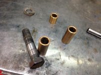
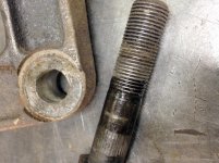
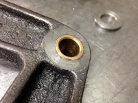
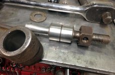
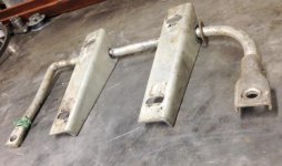
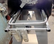
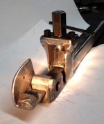
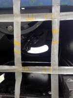
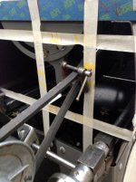
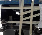
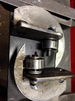
Looking inside I discovered the reason for the wobble in the blade was due to a worn bore on the arm that controls the raising/lowering of the blade.

attachment.php


attachment.php


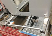
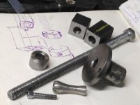
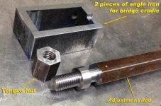
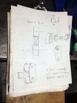
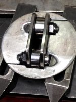
I figured this joint should have a bushing. There was no room for a bearing and it only pivots when the blade arm raises and lowers about 4” up and down. I dug around and found some donor bushings.

attachment.php
 

Attachments

  • MWsawSm_5819.jpg
    MWsawSm_5819.jpg
    64.3 KB · Views: 330
  • MWsawSm_5929.jpg
    MWsawSm_5929.jpg
    55 KB · Views: 324
  • MWsawSm_5931.jpg
    MWsawSm_5931.jpg
    58.8 KB · Views: 324
  • MWsawSm_5928.jpg
    MWsawSm_5928.jpg
    71 KB · Views: 326
  • MWsawSm_5923.jpg
    MWsawSm_5923.jpg
    56.6 KB · Views: 325
  • MWsawSm_5725.jpg
    MWsawSm_5725.jpg
    51.5 KB · Views: 324
  • MWsawSm_5817.jpg
    MWsawSm_5817.jpg
    54.4 KB · Views: 331
To avoid these ads, REGISTER NOW!
OP
2

2oolhound

Well-known member
Joined
Dec 18, 2010
Messages
5,918
Location
BC Canada
The bushing od was .075 and the arm id was .625 so I’d have to ream the bore .062” to accommodate the bushing.

attachment.php


attachment.php


After taking a closer look at the set up used in the saw I realized the bolt used was poorly designed or maybe even improperly replaced at some time in the life of the saw. About 2/3 of the bolts’ threads lay inside the bushing! This explains why the steel on steel pivot was so worn.

attachment.php


A new bolt was in order. The only 5/8” donor bolt I had on hand was this allen head bolt but that was ok as the old original bolt was grade 5 and I understand these ones are grade 8 (the blade arm was torqued to about 120 ft lbs).

attachment.php


attachment.php


I actually had a bad time cutting these threads as I discovered my good Dormer die was faulty and caused some damage to the threads. (I’d gotten it used). I made another new bolt which has a much nicer polished surface for the bushing to ride on. About now I was wishing I’d made a steel bushing just used an oversized bolt as I’m afraid to drill the elbow in the blade arm to install a grease ****** for the bushing there for fear it would weaken the casting too much. I’m just going to leave it as is as it should last me 10 years or as long as I need it.
 

Attachments

  • MWsawSm_5939.jpg
    MWsawSm_5939.jpg
    55.5 KB · Views: 322
  • MWsawSm_5954.jpg
    MWsawSm_5954.jpg
    64.8 KB · Views: 321
  • MWsawSm_5964.jpg
    MWsawSm_5964.jpg
    44.4 KB · Views: 321
  • MWsawSm_5965.jpg
    MWsawSm_5965.jpg
    44.8 KB · Views: 320
  • MWsawSm_5966.jpg
    MWsawSm_5966.jpg
    55.3 KB · Views: 323
OP
2

2oolhound

Well-known member
Joined
Dec 18, 2010
Messages
5,918
Location
BC Canada
While I’m confirming this in my mind it’s off to dismantling the stand, cleaning the sealant off the pieces and sand them in preparation for painting. I’m not trying to use original colors, just what I have on hand. I used a 7” angle grinder with a 5” wire cup for the legs and top and mid height frames and a 4” grinder with small wire cup for the tin on the sides of the saw below the table.

attachment.php


attachment.php


attachment.php


The saw was built much like a unibody car the way it all holds together.

More to come -
 

Attachments

  • MWsawSm_5993.jpg
    MWsawSm_5993.jpg
    52.8 KB · Views: 322
  • MWsawSm_5990.jpg
    MWsawSm_5990.jpg
    45.1 KB · Views: 321
  • MWsawSm_5985.jpg
    MWsawSm_5985.jpg
    57.9 KB · Views: 323

Jim Pelosi

Well-known member
Joined
Nov 30, 2015
Messages
79
Good start. Looking forward to the next parts.

Sent from my moto e6 using Tapatalk
 

RTM

Well-known member
Joined
May 13, 2019
Messages
13,206
Location
SF Bay Area
Nice work so far, that bushing should outlast you in that location, now that you’ve fixed the bolt.
 
OP
2

2oolhound

Well-known member
Joined
Dec 18, 2010
Messages
5,918
Location
BC Canada
Thanks all for the kind words. I've got the painting done.

I went with rattle can hammertone dark gold for the body of the actual saw as I picked up a few tins at the swap meet a while back. Originally it had a silver hammer tone.

attachment.php


For the base I used a mid to dark grey industrial paint I had here. Picture is from the shadow side so it's the lighter tone you see on certain angles.

attachment.php


I picked out about 12 gallon cans of industrial paint from 3 pallets full of various types at a commercial business close out. They were giving it out free but that's all I had room for. This is made for equipment and doesn't need primer but it cleans with mineral spirits so PPE is required to work with it. I sprayed it with my old $400 Webster spray gun (now worth maybe $20 due to those top load siphon style guns now out). I bought mine for real cheap a few years back and love it. A little paint goes a long way (makes you realize how much money they make on rattle cans). The negative is the clean up of the gun afterwards but it beats the **** out of spraying with rattle cans.

This paint takes a day to dry and cure so I'll be going slow. Hope to get the saw assembled andnoperational by the end of the week. (I'm on covid speed)
 

Attachments

  • MWsawSm_6026.jpg
    MWsawSm_6026.jpg
    62.9 KB · Views: 246
  • MWsawSm_6029.jpg
    MWsawSm_6029.jpg
    43.8 KB · Views: 243
OP
2

2oolhound

Well-known member
Joined
Dec 18, 2010
Messages
5,918
Location
BC Canada
Some Progress to date:

While I was into it I dis-assembled the blade up/down control screw mechanism. It’s also non- bushed but was in fine shape so I just repacked some grease in there and cleaned it up.

attachment.php


The main bearing for the blade rotation was removed, inspected and re-assembled. It’s a New Process sealed double roller by the looks of it. No other part number is marked so one would just go by the dimensions for it however it was in excellent shape.

attachment.php


After all the work I’d put into it so far I couldn’t bring myself to assembe the saw without painting the main cast pieces which had never been painted and were quite rusty so I set up my spray tent again, cleaned them up and painted them. I can see my Friday completion date slipping away.

attachment.php


It was gratifying to re-assemble the main parts after they had been freshly painted.

attachment.php


The arc groove that allows angling the blade uses an arc plate guide front and aft in the arc track to control movement and these small inner track guides are just attached by roll pins. I replaced the rear ones with stainless bolts that are locked with 2 bound nuts and bordered with stainless flat washers that limit any in/out movement of the guide plate within the track as there was some slop there.

attachment.php


Here it is upside down on the bench.

attachment.php
 

Attachments

  • MWsawSm_6060.jpg
    MWsawSm_6060.jpg
    52.1 KB · Views: 203
  • MWsawSm_6067.jpg
    MWsawSm_6067.jpg
    55.8 KB · Views: 204
  • MWsawSm_6057.jpg
    MWsawSm_6057.jpg
    54.3 KB · Views: 205
  • MWsawSm_6037.jpg
    MWsawSm_6037.jpg
    44.1 KB · Views: 208
  • MWsawSm_5936.jpg
    MWsawSm_5936.jpg
    56.1 KB · Views: 206
  • MWsawSm_5953.jpg
    MWsawSm_5953.jpg
    45.6 KB · Views: 207
OP
2

2oolhound

Well-known member
Joined
Dec 18, 2010
Messages
5,918
Location
BC Canada
Not to leave well enough alone I had to do something about the ramshackle makeshift motor pivot beam that had been cobbled together and was bent, banged, drilled, and pretty beat up.

attachment.php


From day one this thing bothered me mainly because it wasn’t even square to the frame of the saw. I later realized it had to be canted slightly because as the blade gets angled the drive belt must twist drastically to maintain an adaquate fleet angle of the belt/pulleys.
Non the less I made a sliding tube system incorporating a pivot beam and enclosed it in the ends of the tubes in a loose fashion so the pivot beam can be canted also (one side slightly ahead of the other). The big bonus here and one of the main reasons I went to the trouble was so the motor could be easily removed and stored within the stand thus creating a smaller foot print when not in use.

attachment.php


attachment.php


I’ve never had much to do with table saws but I could see my old buddy’s enclosing of the stand did 2 things.
1, it created storage space for guides, blade wrenches, blades etc. and
2, it collected sawdust (as there was a fair amount of sawdust in there I had to deal with.
Since I intend to use the saw for cutting metal quite often and because the original plywood sides were so rough looking I’ve decided to make some metal enclosures to replace the old plywood ones. I’m concerned the odd spark from cutting metal could ignite the sawdust and wood sides.

attachment.php


Another thing I'm pondering is using a dust collector but I know nothing of them. If the enclosure is fairly airtight like it was, I'm thinking I could have an option of hooking a vacuum cleaner to the underneath area to extract saw dust or just let it collect down there. If anyone has any knowledge to add regarding dust collection please chime in.
 

Attachments

  • MWsawSm_6046.jpg
    MWsawSm_6046.jpg
    40.7 KB · Views: 204
  • MWsawSm_6078.jpg
    MWsawSm_6078.jpg
    45.7 KB · Views: 203
  • MWsawSm_6069.jpg
    MWsawSm_6069.jpg
    52 KB · Views: 203
  • MWsawSm_6082.jpg
    MWsawSm_6082.jpg
    63.7 KB · Views: 204
Last edited:
OP
2

2oolhound

Well-known member
Joined
Dec 18, 2010
Messages
5,918
Location
BC Canada
A little more progress (the end is still in sight)

These are the components for adjusting the belt tension and angle. The belt only needs 1” of adjustment for alignment but I added quite a bit more thread so I can use a longer belt if necessary in the future.

attachment.php


Here it is all welded in place. As it turns out the old bent bar used for the motor pivot mount was bent the wrong way. The motor must be turned slightly the other way to align the pulley when tilting the blade. The big change is the motor slides to the left on the pivot rod drastically. The pivot rod and the angle crank (sliding tubing) control the fleet angle of the belt. I left the head on the bolt so a drill can be used to unthread the adjuster completely when storing the motor in the storage compartment.

attachment.php


Here is a shot of the stand showing the saw dust chute. The top of the deck under the saw is closed off except for the opening to the chute that goes to the bottom where a drawer will collect and store the saw dust. You’ll see in the next photo a maroon outer cover seals the chute from the back side. I will also cut a round hole and fit that with a vacuum spigot so a shop vac can be hooked up if desired. I’ll wire it so the vacuum comes on when the saw is running.

attachment.php


attachment.php


This last shot shows a bottom rail mounted in the very bottom (stand is upside down in the photo). A 4 wheeled dolly is now fitted against this rail so the saw is on wheels. I’ll make the dolly “quick detach” in case I don’t want it on wheels while working with the saw. Remember the stand is upside down in the photo but the saw dust drawer will sit on the top of the wheeled dolly.

attachment.php


There’s still a ton of work to do on this, make a storage door, wire it, disassemble and repaint, and on and on.

.
 

Attachments

  • MWsawSm_6151.jpg
    MWsawSm_6151.jpg
    52.5 KB · Views: 178
  • MWsawSm_6147.jpg
    MWsawSm_6147.jpg
    41.7 KB · Views: 178
  • MWsawSm_6132.jpg
    MWsawSm_6132.jpg
    57.3 KB · Views: 178
  • MWsawSm_6116.jpg
    MWsawSm_6116.jpg
    50.2 KB · Views: 181
  • MWsawSm_6104.jpg
    MWsawSm_6104.jpg
    42.5 KB · Views: 177
OP
2

2oolhound

Well-known member
Joined
Dec 18, 2010
Messages
5,918
Location
BC Canada
It's been a couple weeks since I posted but I've managed to complicate things pretty good.

Here's the sawdust drawer on the bottom which is just a slide in fit with no slides because they would allow sawdust to pile into their space. A tunnel was built and then the drawer is a tight fit into the tunnel so there is very little room for any sawdust to go except in the drawer. I also have a vacuum hole on the opposite side as the drawer face as an alternative. Don't forget this is all being built from scrap.

attachment.php


This is the opposite side as the drawer face. You can see the tunnel at the bottom that the drawer fits in. The triangular shroud in the middle of the stand is not in place yet but it has the round fitting for the vacuum hose. Brackets were added to store the table extensions when the unit is in storage.

attachment.php


This is the main power box. It is located in a small pocket on the side of the drawer tunnel. The round connector is a counter sunk male 120V connector. A regular extension can be plugged right into it to power the box which will have the saw motor plugged into it and a vacuum. This box is switched at the front of the saw.

attachment.php


I've added a 1 1/2" X 1 1/2" piece of tubing along the front top to mount off/on switches for the power to the blade and for lighting for inside the cabinet. There will also be light shining down on the front angle guage.

attachment.php


I've added a fence holster as well as an angle guide holder on the front for easy access to these common accessories. The wine colored crank handle is still what sticks out the furthest on this side (front) so I'm not adding anything to the foot print when it's in storage. I thought these additions made the front look cluttered and messy so I made a basket that fits in between them. I can keep a push stick and any other needed items in the basket when using the saw.

attachment.php


Well, I broke protocol and went and bought some led strip light for illumination of the interior and the front guage. The white plastic switch that was included won't cut it so I replaced it with a vintage 120V toggle. This toggle will be were you can see it in the 4th. photo on the left while the saw power toggle will be on the right.

attachment.php


attachment.php
 

Attachments

  • MWsawToggleSm_6184.jpg
    MWsawToggleSm_6184.jpg
    54.5 KB · Views: 160
  • MWsawSm_6183.jpg
    MWsawSm_6183.jpg
    48.1 KB · Views: 160
  • MWsawSm_6172.jpg
    MWsawSm_6172.jpg
    43.4 KB · Views: 161
  • MWsawSm_6170.jpg
    MWsawSm_6170.jpg
    45.1 KB · Views: 162
  • MWsawSm_6165.jpg
    MWsawSm_6165.jpg
    31.8 KB · Views: 160
  • MWsawSm_6166.jpg
    MWsawSm_6166.jpg
    38.6 KB · Views: 160
  • MWsawSm_6162.jpg
    MWsawSm_6162.jpg
    42.2 KB · Views: 160
OP
2

2oolhound

Well-known member
Joined
Dec 18, 2010
Messages
5,918
Location
BC Canada
It was apparent that some light was necessary inside for the storage shelves so I went with led strip lights. These photos have just been taken as it was getting dark when I was just finishing the 1st fitting so it would be a nice time for photos.

I wanted to illuminate the angle guage for those times when you wanted to finish your work but were running out of daylight (and since I was lighting the interior anyway).

attachment.php


The storage interior will have lots of light. There is still lots of finicky work in cutting and fitting these strip lights. There is a 2nd power box on the top shelf where the power supply for the led's plug in. This 2nd power box is always live (when the main extension cord is attached) and is not switched like the main power box on the outside where the motor and vacuum plug in.

attachment.php


You can see the basket that was added to the front in this last shot.
.
.
 

Attachments

  • MWsawSm_6199.jpg
    MWsawSm_6199.jpg
    40.6 KB · Views: 161
  • MWsawSm_6189.jpg
    MWsawSm_6189.jpg
    42 KB · Views: 161
To avoid these ads, REGISTER NOW!
OP
2

2oolhound

Well-known member
Joined
Dec 18, 2010
Messages
5,918
Location
BC Canada
The saw is a small one, 7.5". After getting carried away this far on it I've been wishing I'd had a 10" to start with. I won't use it much anyway so I'm liking it. I had to stash it at the back of the line as some more pressing work came along. I have a bit of welding to do and then paint the shroud I've added since painting the original stand and parts. Not much left but I won't get to it for a while yet. I'll post some finished shots though when I finally get it complete.
 

bubinga

Well-known member
Joined
Jul 26, 2014
Messages
12,744
Location
Bridgeport Ohio. (Across River From Wheeling WV)
The saw is a small one, 7.5". After getting carried away this far on it I've been wishing I'd had a 10" to start with. I won't use it much anyway so I'm liking it. I had to stash it at the back of the line as some more pressing work came along. I have a bit of welding to do and then paint the shroud I've added since painting the original stand and parts. Not much left but I won't get to it for a while yet. I'll post some finished shots though when I finally get it complete.

Oh, OK thanks, I think IIRC the one I have on mine, Is a 8" blade.
I have a saw almost like it, I just got done putting the motor on Sunday.
The PO made dome type of motor mount for it, It goes in with two large dowels, like a Craftsman drill press motor.
I have the OEM stand, But had taken it apart to get it in the car. So I just have it mounted on a Stanley work mate.
I have a new circular saw blade, floating around here somewhere, I am just going to use that for now.
Oh, the seller of mine called me a half hour before I got there to look at it, and said he tried to run it, but it won't start.
I don't remember what he was asking, $40.00 IIRC, But He said, he thinks it's just the cord. But the stand had some sort of switched outlet on it,
but I did away with the outlet of course, when I mounted it to the work mate.
It has a old craftsman motor on it, with a toggle switch, and it turns on and off with that switch.
Anyways, he told me since he wasn't sure about the motor, "how about $20.00" I was all over it.

Thanks for the reply!!
Yours looks really nice though!!
Oh yes, looking forward to seeing yours all done.
 
OP
2

2oolhound

Well-known member
Joined
Dec 18, 2010
Messages
5,918
Location
BC Canada
I'm not sure of the correct terminology but I've been calling the tilt guage on the front body panel the "angle guage" and I've been calling the Guide that slides in the grooves on the table top the "angle guide".

I think you are referring to the latter and in that case the bar on the guide (guage) that slides in the table groove is 11/16" x 1/4"and the slots or grooves in the table top is a tight 3/4" x 1/4".
 

bubinga

Well-known member
Joined
Jul 26, 2014
Messages
12,744
Location
Bridgeport Ohio. (Across River From Wheeling WV)
I'm not sure of the correct terminology but I've been calling the tilt guage on the front body panel the "angle guage" and I've been calling the Guide that slides in the grooves on the table top the "angle guide".

I think you are referring to the latter and in that case the bar on the guide (guage) that slides in the table groove is 11/16" x 1/4"and the slots or grooves in the table top is a tight 3/4" x 1/4".

Oh, see I always called it a miter gauge.
No, Mine is smaller.
 
OP
2

2oolhound

Well-known member
Joined
Dec 18, 2010
Messages
5,918
Location
BC Canada
I'm on the west coast and close enough to Oregon that we have a lot of smoke in the air. We are warned to stay indoors so it's given me time to post some progress I made a month or two ago. My heart goes out to all those who are suffering great losses and hardships due to the forest fires.

I got looking at the belt tension adjuster (post 13) and decided the other side needed some kind of lock on it so it would remain in position. I also didn't like the idea you had to use a drill to turn all those threads out of the adjustment lug in order to store the motor when not in use.

attachment.php


I cut 2 - 4" slits along the top surface of the external female tube so I could weld a nut on the end of the tongue that was made by doing the slits. By raising or lowering this tongue the inner male tube could be locked or released easily. (idea stolen from Royce's receiver hitch locks)

I'd need some type of small bridge fitment to push or pull on the tongue. I cut some 1" sections of angle iron to cradle around the end of the outer tube and attach a collar atop of so I could install the grooved and threaded piece of hex bar I machined as the adjustment rod.

attachment.php


attachment.php


attachment.php


To get away from needing to use a drill to unscrew the long adjuster rod on the other side to detach the motor I drilled the male inner sliding tube right through and installed a retaining cap on the side that could be flipped up to clear the through hole for the long motor pivot rod or flipped down to keep it captive in place.

attachment.php


Now removing the motor is as quick and simple as lifting the flap and sliding the pivot rod out after removing the belt.
.
 

Attachments

  • TubeClampSm_6302.jpg
    TubeClampSm_6302.jpg
    25.2 KB · Views: 53
  • PivotRodFlapSm_6321.jpg
    PivotRodFlapSm_6321.jpg
    40.3 KB · Views: 54
  • MtrAdjTubesSm_6218.jpg
    MtrAdjTubesSm_6218.jpg
    72.1 KB · Views: 53
  • AdjTubePtsSm_6296.jpg
    AdjTubePtsSm_6296.jpg
    65.8 KB · Views: 53
  • AdjTubePtsSm_6253.jpg
    AdjTubePtsSm_6253.jpg
    61.7 KB · Views: 53
Last edited:
OP
2

2oolhound

Well-known member
Joined
Dec 18, 2010
Messages
5,918
Location
BC Canada
Wow!! You are a Good Machinist!!

Don't say that too loud around here!

Machinist = 5 year apprenticeship - Good Machinist = a lifetime
Welder = 5 year apprenticeship
= me, pretty much a beginner. Top that off with my 40 yr old welders (both for $100) and my 70 yr. old ramshackle atlas lathe and I'm a long way off from being a machinist but this is why I do all this fiddling on this stuff, to learn. (and don't look too close at my welds). I went over 30 years without a garage and it's been about 10 years since I mounted a vise to a workbench and discovered GJ. Me and my littler garage/shop have come a long way but I'm enjoying it even though it often takes days to accomplish some simple little thing eventually you come out the other side and have the satisfaction of creating something from junk.

The current dilemma I face with this project is sealing off the back of the saw so saw dust recovery will be efficient. The obstacle is the belt path from the motor to the blade spindle pulley. This is a moving area because of the tilt and up and down on the saw blade adjustments.

attachment.php


Plotting the belt movement was done by marking the borders with masking tape. It is the central square you see. It was a large opening for the belt which I think would make establishing a flow of saw dust downward very inefficient.

attachment.php


Then I thought what if I used a belt tensioner that acted like a kind of girdle the belt had to squeeze through. This could reduce the belt opening area substantially and make the saw dust flow possible.

attachment.php


Using a small C-clamp about the same size of my imaginary belt tentioner I plotted a new opening.
attachment.php


The resulting opening plotted can be seen here in the diagonal opening in the center. The other issue is on the left you can see faint red marks. These show the angle of the belt at full tilt. My belt tentioner would have to travel sideways on the diagonal AND rotate to accommodate this belt angle.

attachment.php


Fun,

I found a 1/8" x 4" washer, some allen pan head bolts, shims, 2 used bearings the right thickness for the belt and some flat bar to mount the bearings on.

attachment.php


I wanted the bearings to be serviceable so I cut the 4" washer in two and also cut out the center for the bearing carrier assembly on a portaband table.

attachment.php
 

Attachments

  • TableRearSealSm_6351.jpg
    TableRearSealSm_6351.jpg
    58.3 KB · Views: 37
  • PlotBeltTravSm_6425.jpg
    PlotBeltTravSm_6425.jpg
    43.1 KB · Views: 38
  • BeltGuidePlanSm_6352.jpg
    BeltGuidePlanSm_6352.jpg
    42.3 KB · Views: 37
  • RearTblSealSm_6354.jpg
    RearTblSealSm_6354.jpg
    50.7 KB · Views: 36
  • RearTableSealSm_6446.jpg
    RearTableSealSm_6446.jpg
    42.4 KB · Views: 37
  • RotoMntBeltTenSm_6368.jpg
    RotoMntBeltTenSm_6368.jpg
    51.9 KB · Views: 31
  • RotoMntBeltTenSm_6359.jpg
    RotoMntBeltTenSm_6359.jpg
    42.8 KB · Views: 31
Last edited:
OP
2

2oolhound

Well-known member
Joined
Dec 18, 2010
Messages
5,918
Location
BC Canada
With the bearing carrier assembly done (wish I'd have sprung for some needle bearings for a smaller tighter assembly) I laid out how much I'd need to grind to remove the allen head bolts once it was welded.

attachment.php


Here it is ready for welding.

attachment.php


The edges of the 4" washer will have to slide in a narrow slot so I clamped it down everywhere I could before welding to keep it flat. I wanted to just spot small welds everywhere I could reach in to minimize heat distortion.

attachment.php


A final clamp was installed to hold the bearing carrier assembly down, centered depth-wise and squared between the washer halves.

attachment.php


This is the unit that can rotate and move diagonally to facilitate the belt positions during blade adjustments.

attachment.php


Here it is dis-assembled for bearing replacement.

attachment.php


The belt pokes in easily enough without stressing the belt.

attachment.php


I sure hope it will work!!! I've started to work on the rear panel at the back of the saw that this will fit into but no pics yet and as I'd explained above I've had to put this project on the back burner until I:
plumb a sink, tub and toilet,
tile a floor,
fix my E-brake on my truck
and, and and,
ha ha, I'm hoping I can get back at this to complete and paint it and then finally store it for future use before snow flies. I'll post photos as progress is made.
 

Attachments

  • RotoMntBeltTenSm_6372.jpg
    RotoMntBeltTenSm_6372.jpg
    45.7 KB · Views: 32
  • RotoMntBeltTenWeld_6378.jpg
    RotoMntBeltTenWeld_6378.jpg
    80.8 KB · Views: 32
  • RotoMntBeltTenWeldSm_6386.jpg
    RotoMntBeltTenWeldSm_6386.jpg
    50.5 KB · Views: 32
  • RotoMntBeltTenWeldSm_6392.jpg
    RotoMntBeltTenWeldSm_6392.jpg
    56.6 KB · Views: 32
  • RotoMntBeltTenSm_6410.jpg
    RotoMntBeltTenSm_6410.jpg
    42.4 KB · Views: 32
  • RotoMntBeltTenPtsSm_6400.jpg
    RotoMntBeltTenPtsSm_6400.jpg
    54.2 KB · Views: 30
  • BeltBearing Assembly-w-BeltSm_6412.jpg
    BeltBearing Assembly-w-BeltSm_6412.jpg
    40.1 KB · Views: 30
Last edited:
OP
2

2oolhound

Well-known member
Joined
Dec 18, 2010
Messages
5,918
Location
BC Canada
Thanks guys.

I think I'm just frustrated at how everything today is manufactured bare bones "good 'nough". When I grew up there was still plenty of ginger bread trim on designs of everything, tools, homes, furniture, most things. The creator imparted a little artistic flare to compliment the creation and tried to make it as good as it could be. Today it's all about simplicity of mass production and use as little material of the lowest quality required. While that isn't such a bad thing we have lost something in the process. Rather than add functionality they make an add on unit they can also sell you.

I'm just blundering my way through this whereas someone who's worked a lot with different table saws and dust collectors likely sees some folly of all my efforts here. It's still a fulfilling way to past time for me. "Do the best you can with what you've got" a saying I garnered from a movie when I was young. Ironically this kind of activity keeps me from watching too much tv today where there seems to be less and less wisdom to be garnered.

I just hope it works as envisioned when I'm done. :dunno:
 
To avoid these ads, REGISTER NOW!
Top Bottom