To avoid these ads, REGISTER NOW!

Adding motion sensor to 4 way switch setup?

jpcjguy

Well-known member
Joined
Jan 6, 2014
Messages
1,480
Location
Richmond, VA
Hi all,

I have the carriage lights on the front of the garage hooked up to 3 switches (two 3-way and one 4-way). So I can control them from inside the house and just inside the two man doors in the garage.
Is it possible to add a motion sensor to this setup?

Thanks!
 
To avoid these ads, REGISTER NOW!

AntonLargiader

Well-known member
Joined
Nov 20, 2016
Messages
1,372
Location
Charlottesville, VA
If you connected it across the two travelers, it would make both travelers hot and the light would go on regardless of the switch position. Obviously you'd want to know this was arranged this way so that you never counted on a traveler being dead when you worked on the circuit.
 

Terry D

Well-known member
Joined
Mar 25, 2015
Messages
2,202
Location
St. Louis, MO.
Sure, are you replacing the lights with integrated sensors or just putting one motion sensor in the circuit.

To add a motion sensor to to circuit, just intercept the power going to the first light and wire your sensor in there. You can mount the sensor anywhere then.

Your switches would have to be left alone, and left in the on position and only used when you want to override the sensor and have the lights on all the time at night

Sent from my SM-G960U using The Garage Journal mobile app
 

tyme2par4

Well-known member
Joined
May 16, 2016
Messages
571
Location
NH
Do you want the motion sensor to only function when the light is switched on, or are you hoping to use it as a 4th switch?
If only when the light is switched on, it's as simple as wiring it in just before the power enters the light fixture.
 
OP
J

jpcjguy

Well-known member
Joined
Jan 6, 2014
Messages
1,480
Location
Richmond, VA
So the goal is to be able to turn the lights on and off from the 3 locations that I currently have and have a motion sensor turn them on when I drive up to the garage. Rather not have a separate motion light mounted on the garage "front". So ultimately, total control from the switches and when in the "off position", the motion sensor can turn them on for 5 or 10 minutes and then they go off again.....


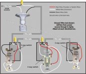
Attached is how the wiring currently done. In my case, there is a junction box where the power wires, light wires and 14-2 wire from one of the 3-way switches all come together.
 

Attachments

  • 4 wire switch setup.JPG
    4 wire switch setup.JPG
    38.2 KB · Views: 72

Terry D

Well-known member
Joined
Mar 25, 2015
Messages
2,202
Location
St. Louis, MO.
So the goal is to be able to turn the lights on and off from the 3 locations that I currently have and have a motion sensor turn them on when I drive up to the garage. Rather not have a separate motion light mounted on the garage "front". So ultimately, total control from the switches and when in the "off position", the motion sensor can turn them on for 5 or 10 minutes and then they go off again.....


Attached is how the wiring currently done. In my case, there is a junction box where the power wires, light wires and 14-2 wire from one of the 3-way switches all come together.

You need to intercept the hot going to the first light. There is a black and red on the sensor, black is line and red is load. The white connects to the white to the light, no need to intercept it, just wire nut it with it. BE AWARE, the other white wires are travelers, dont connect it there.

Your switches will become almost useless. They need to be left in the position that will have constant power to the motion sensor. Your motion sensor now becomes the switch. The only time you would use those switches would be to override the sensor.
 
OP
J

jpcjguy

Well-known member
Joined
Jan 6, 2014
Messages
1,480
Location
Richmond, VA
You need to intercept the hot going to the first light. There is a black and red on the sensor, black is line and red is load. The white connects to the white to the light, no need to intercept it, just wire nut it with it. BE AWARE, the other white wires are travelers, dont connect it there.

Your switches will become almost useless. They need to be left in the position that will have constant power to the motion sensor. Your motion sensor now becomes the switch. The only time you would use those switches would be to override the sensor.

Ok - thanks for the explanation. So it appears that I can't really get the setup i want based on my current configuration. Not a big deal. If I do want a motion light, I will have to run it separately.
 

Terry D

Well-known member
Joined
Mar 25, 2015
Messages
2,202
Location
St. Louis, MO.
Now that I have thought about it more. The only way it will work and still be able to use your switches normally is to parallel the sensor with the 4-way switch circuit. The line side would connect to the power feeding the circuit and the load would connect to the first light. This setup would back feed power into the sensor when the switches are used and the sensor is not providing power to the lights. I'm not sure it would damage it or not. I have done this with photo eyes with a override switch and have not had any problems.

So if that diagram you posted is how it is wired, you would connect the line side to the black and white connection in the box with the light, that is your constant hot. The load side would splice to the black going to the light. You could never turn your motion sensor off that way, except by the breaker, probably would not need to, but you could override it with the switches

I could draw this out for you , if needed
 
Last edited:

AntonLargiader

Well-known member
Joined
Nov 20, 2016
Messages
1,372
Location
Charlottesville, VA
It's doable. It just depends on how things are laid out. Is this an attached garage? Where do you want the sensor? Is there unswitched power available where you want the sensor or near the lights? Basically you just override the signal from the switches with the sensor, but that could be easy or difficult depending on where you have power and neutral.
 
OP
J

jpcjguy

Well-known member
Joined
Jan 6, 2014
Messages
1,480
Location
Richmond, VA
Now that I have thought about it more. The only way it will work and still be able to use your switches normally is to parallel the sensor with the 4-way switch circuit. The line side would connect to the power feeding the circuit and the load would connect to the first light. This setup would back feed power into the sensor when the switches are used and the sensor is not providing power to the lights. I'm not sure it would damage it or not. I have done this with photo eyes with a override switch and have not had any problems.

So if that diagram you posted is how it is wired, you would connect the line side to the black and white connection in the box with the light, that is your constant hot. The load side would splice to the black going to the light. You could never turn your motion sensor off that way, except by the breaker, probably would not need to, but you could override it with the switches

I could draw this out for you , if needed

Ok - kind of makes sense - can you edit the image that I attached? Thanks!
 
To avoid these ads, REGISTER NOW!
OP
J

jpcjguy

Well-known member
Joined
Jan 6, 2014
Messages
1,480
Location
Richmond, VA
It's doable. It just depends on how things are laid out. Is this an attached garage? Where do you want the sensor? Is there unswitched power available where you want the sensor or near the lights? Basically you just override the signal from the switches with the sensor, but that could be easy or difficult depending on where you have power and neutral.

It is a detached garage. The sensor would be located either under the soffit or right by one of the lights. I do have full access to the panel and all wiring right now. Getting insulation next week and then drywall. I have attached a pic of the garage that was used in another thread about HVAC - but you get the idea of the building.
 

Attachments

  • hvac2.jpg
    hvac2.jpg
    144.1 KB · Views: 29

AntonLargiader

Well-known member
Joined
Nov 20, 2016
Messages
1,372
Location
Charlottesville, VA
So I assume there's a panel in the garage and a switch leg coming back to the house for the one switch? And, more importantly, the power does actually go first to the lights and then to the switches? In that case, pretty easy. Just wire the motion sensor into the lights on the right side of the lamp in your diagram. You have hot, neutral, and the switched hot right there. I suspect this is what Terry's going to sketch up.
 

Steve W.

Well-known member
Joined
Mar 27, 2019
Messages
1,261
Location
Southwest oHIo
All of the motion-sensor lights I have ever had required full-time power to the sensor. If you turn the power off, then back on within a short time, the light stays ON, regardless of sensed motion. To reset, you have to turn the switch(es) off for about 30 seconds, then on again to arm the motion sensor.

If you can guarantee at least 30 seconds between power off/on cycles, you would still have to guarantee that the last person to activate a switch would leave it on, you might have a chance.

I would say you would be better off with a separate light.

How long do you need to have that light on? If it's just to provide a bit of light while you get in or out of your vehicle, why not look into a solar-recharged LED flood light? Some are bright enough to see clearly and will stay on as long as they sense motion. They do time out about 30 seconds after the last motion, so they are not on for an excessive amount of time.

I got some of the "As seen on TV" lights at Menard's. About $20 each, they do a fine job. :thumbup:

.
 
OP
J

jpcjguy

Well-known member
Joined
Jan 6, 2014
Messages
1,480
Location
Richmond, VA
So I assume there's a panel in the garage and a switch leg coming back to the house for the one switch? And, more importantly, the power does actually go first to the lights and then to the switches? In that case, pretty easy. Just wire the motion sensor into the lights on the right side of the lamp in your diagram. You have hot, neutral, and the switched hot right there. I suspect this is what Terry's going to sketch up.

That is correct. Panel in the garage. I have a 3 way wire going to a switch in the house. This goes to the 4 way switch at the 1st man door. Power actually goes to a junction box in the attic space where the light circuits come to and also the 14/2 from the 2nd man door 3 way switch. Just like the picture - which I updated.
 

Attachments

  • 4 wire switch setup with junction.jpg
    4 wire switch setup with junction.jpg
    70 KB · Views: 50

Terry D

Well-known member
Joined
Mar 25, 2015
Messages
2,202
Location
St. Louis, MO.
Ok - kind of makes sense - can you edit the image that I attached? Thanks!
Sorry i didn't get it drawn up last night. Hopefully i can explain it so it makes sense. If it is wired like the drawing, all the wiring will be in the box with the first light. You have your power coming in on a 2-wire romex. The black is spliced to a white leaving the box going to a switch. You need to connect the black (line) of the sensor to this connection, so you will have 3 wires connected to this splice.

The red (load) of the sensor will connect to where the black wire is going to the light, since this is controlling 2 lights, there possibly is already a aplice there to tie into. If not, you will have to pigtail.

The white from the sensor simply connects to the white of the light, there possibly is a splice there also.

With this setup, the sensor will override the switches no matter what position they are in. You will still be able to use your switches when the sensor is not detecting motion. One thing to note, when the light is on from sensing motion from the detector, you will not be able to turn the lights off by the switches. You will have to wait for the sensor to time out.

Sent from my SM-G960U using The Garage Journal mobile app
 

larry4406

Well-known member
Joined
Jan 27, 2006
Messages
19,562
Location
Northern Virginia
Terry D - please markup the wiring diagram the OP provided as I am interested.

I have a 4-way switch circuit for my attached garage lighting and the family leaves the garage light on all night. I would like for a sensor to turn it off if its left on and no one is in there.
 

Terry D

Well-known member
Joined
Mar 25, 2015
Messages
2,202
Location
St. Louis, MO.
Terry D - please markup the wiring diagram the OP provided as I am interested.

I have a 4-way switch circuit for my attached garage lighting and the family leaves the garage light on all night. I would like for a sensor to turn it off if its left on and no one is in there.

https://www.homedepot.com/p/Defiant...eqBPLmlxj1YQKaGYTHhoCCbgQAvD_BwE&gclsrc=aw.ds


Im am not good at figuring out how to edit a picture. I included a link for a motion sensor from Home depot.

Black is Line (constant power feeding sensor )

Red is Load (power out from sensor when motion is detected)

White is neutral connection.

Do not confuse these colors with the colors on the switches

Like I said in earlier posts, I have done something similar with photo eyes in the past, and it worked with out a problem. I have never tried it with a motion sensor. It will back feed power through the red wire into the sensor when no motion is detected and you are using the switches to turn the lights on. I don't know if this will have a effect on the sensor as far as damaging it. I know it does not damage a photo eye. It will bypass the switches and turn the lights on no matter what position the switches are in. The only down fall is you could never turn off power to the motion sensor by the switches. The lights will always come on when it senses motion and will have to wait till the sensor times out for them to go out. But under normal conditions, the lights will turn on and off by the switches
 

Attachments

  • 4 wire switch setup (1).JPG
    4 wire switch setup (1).JPG
    61 KB · Views: 49
Last edited:
OP
J

jpcjguy

Well-known member
Joined
Jan 6, 2014
Messages
1,480
Location
Richmond, VA
https://www.homedepot.com/p/Defiant...eqBPLmlxj1YQKaGYTHhoCCbgQAvD_BwE&gclsrc=aw.ds


Im am not good at figuring out how to edit a picture. I included a link for a motion sensor from Home depot.

Black is Line (constant power feeding sensor )

Red is Load (power out from sensor when motion is detected)

White is neutral connection.

Do not confuse these colors with the colors on the switches

Like I said in earlier posts, I have done something similar with photo eyes in the past, and it worked with out a problem. I have never tried it with a motion sensor. It will back feed power through the red wire into the sensor when no motion is detected and you are using the switches to turn the lights on. I don't know if this will have a effect on the sensor as far as damaging it. I know it does not damage a photo eye. It will bypass the switches and turn the lights on no matter what position the switches are in. The only down fall is you could never turn off power to the motion sensor by the switches. The lights will always come on when it senses motion and will have to wait till the sensor times out for them to go out. But under normal conditions, the lights will turn on and off by the switches

So I could wire in a switch before the sensor and be able to "turn off" the motion sensor if needed, correct? or would back feed into the sensor through the red be an issue?
 

Terry D

Well-known member
Joined
Mar 25, 2015
Messages
2,202
Location
St. Louis, MO.
So I could wire in a switch before the sensor and be able to "turn off" the motion sensor if needed, correct? or would back feed into the sensor through the red be an issue?

Yes, if you wire a single pole switch before the sensor on the black wire but after the splice with the yellow wire nut, it will take the sensor out of the circuit and function like a normal 3-way switch circuit
 
To avoid these ads, REGISTER NOW!
Top Bottom