To avoid these ads, REGISTER NOW!

Old Leland 7 wire motor color coded / no diagram

lafester

Well-known member
Joined
Mar 1, 2017
Messages
2,191
Location
Northern CO
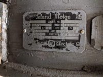
Hopefully someone can help me out with this motor.

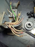
PO Had the black, yellow, blue and red together on one line and green red and white on the other.
I am getting a hum but no movement with this configuration.
I guess I will open it up and see what goes where but I would like to see how others have theirs wired.
I am looking for 115v and I need to know if this is reversible. It does have a capacitor on top.
I have meters available but little knowledge on how to test.
 

Attachments

  • IMG_20210105_172913.jpg
    IMG_20210105_172913.jpg
    85.1 KB · Views: 45
  • PXL_20201112_223113918.jpg
    PXL_20201112_223113918.jpg
    153.4 KB · Views: 51
To avoid these ads, REGISTER NOW!

DeeKay

Well-known member
Joined
Nov 25, 2020
Messages
448
Location
Colorado
Simple things first, does the motor spin freely? If so, see below.

I'm counting seven leads from the motor, every single speed, dual voltage, single phase motor I've seen only has six. Is one of those grounded to the case? it's hard to tell the colors from the pic but is the third from the bottom a green wire? If so check for continuity between it and bare metal on the case of the motor. Also I think one of your two reds might be an orange.

This motor could be pre-NEMA but going by Current standard colors you should wire it like this for 120v if that one wire is a ground and one of the reds is an orange. [T2(White)T4(Yellow)T5(Black)]-- line, [T1(Blue)T3(Orange)T8(Red)]--line

To reverse flip T5 and T8.
 
Last edited:
OP
L

lafester

Well-known member
Joined
Mar 1, 2017
Messages
2,191
Location
Northern CO
Thanks, yeah the green one is third up. I doubt it is to the frame as it was wired to power previously, but I will check. I have read in my searching that the green wire equals nema orange. The two red wires are confusing so I'll break it open and see where they go.

Simple things first, does the motor spin freely? If so, see below.

I'm counting seven leads from the motor, every single speed, dual voltage, single phase motor I've seen only has six. Is one of those grounded to the case? it's hard to tell the colors from the pic but is the third from the bottom a green wire? If so check for continuity between it and bare metal on the case of the motor. Also I think one of your two reds might be an orange.

This motor could be pre-NEMA but going by Current standard colors you should wire it like this for 120v if that one wire is a ground and one of the reds is an orange. [T2(White)T4(Yellow)T5(Black)]-- line, [T1(Blue)T3(Orange)T8(Red)]--line

To reverse flip T5 and T8.
 
OP
L

lafester

Well-known member
Joined
Mar 1, 2017
Messages
2,191
Location
Northern CO
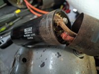
Couple pics of the inside. The green and white go directly to the middle and outer windings. The inner winding goes to the capacitor.

Took me awhile to get this beast open.


Simple things first, does the motor spin freely? If so, see below.

I'm counting seven leads from the motor, every single speed, dual voltage, single phase motor I've seen only has six. Is one of those grounded to the case? it's hard to tell the colors from the pic but is the third from the bottom a green wire? If so check for continuity between it and bare metal on the case of the motor. Also I think one of your two reds might be an orange.

This motor could be pre-NEMA but going by Current standard colors you should wire it like this for 120v if that one wire is a ground and one of the reds is an orange. [T2(White)T4(Yellow)T5(Black)]-- line, [T1(Blue)T3(Orange)T8(Red)]--line

To reverse flip T5 and T8.
 

Attachments

  • IMG_20210106_215338.jpg
    IMG_20210106_215338.jpg
    120.3 KB · Views: 33
  • IMG_20210106_215346.jpg
    IMG_20210106_215346.jpg
    106.2 KB · Views: 29

DeeKay

Well-known member
Joined
Nov 25, 2020
Messages
448
Location
Colorado
Ok, before we get in too deep measuring windings and whatnot. There's a chance this was wired ok from the PO. Did they say that the motor was operational when they had it?

Also again does the shaft spin freely?

Probably should have had you do this from the start, you mentioned the motor hums when energized which brings into question the start circuit.

One simple way you can check the switch, cap and start winding is to wire the motor up the way it was and try to start it. When it's energized try to get the shaft spinning by hand.(be careful, 1hp will tear your *** up) If it starts that way, there's probably an issue somewhere in the start circuit. From here you would troubleshoot the individual components like below.

Measure across your capacitor with your meter and make sure it's still good, caps don't last forever. Compare your reading with the mF rating on the capacitor, doesn't have to be exact but should be close.

Next measure continuity across the centrifugal switch with it closed; either push it closed manually with the motor apart and measure, or put the motor back together and measure between the red wire going to the switch and the wire on the capacitor coming from the switch. You should have good continuity here, if not there's a problem with the switch, this wouldn't be surprising given the age of the motor.

While your at it, measure all your leads to ground just to make sure this thing is worth troubleshooting in the first place.

If all that checks out, we can dive into measuring different windings. Still wondering what that 7th wire does though. Maybe one of the old heads here more familiar with older motors would know.
 
OP
L

lafester

Well-known member
Joined
Mar 1, 2017
Messages
2,191
Location
Northern CO
I have a couple more pics. I tried to test the capacitor but my meter doesn't seem to read anything. I tried it on 2 other capacitors with no luck so I assume my meter *****.

I'll do some more checking tomorrow.

So the black switch has the blue wire and black wire, along with another black wire going to a winding. The other switch has a white wire from the capacitor and the red wire going to power.
 

Attachments

  • IMG_20210109_171623.jpg
    IMG_20210109_171623.jpg
    108.2 KB · Views: 21
  • IMG_20210109_171931.jpg
    IMG_20210109_171931.jpg
    127.5 KB · Views: 21
  • IMG_20210109_170012.jpg
    IMG_20210109_170012.jpg
    126.3 KB · Views: 22
OP
L

lafester

Well-known member
Joined
Mar 1, 2017
Messages
2,191
Location
Northern CO
4 wire group:

Red - To centrifugal switch (connects to white / capacitor)
Blue - To black (thermal?) switch
Black - To black switch
Yellow - To upper winding

3 wire group

Red - upper winding
Green - lower winding
White - lower winding

Capacitor

White - To Centrifugal switch (connects to red / power)
Red - lower winding

Black Switch

Black - To upper winding
Blue - To power
Black - To power

This black switch is confusing me but I am easily confused.
 
Last edited:
To avoid these ads, REGISTER NOW!
OP
L

lafester

Well-known member
Joined
Mar 1, 2017
Messages
2,191
Location
Northern CO
I put the motor back together and it fired right up using the original wiring.
The centrifugal switch seemed to be stuck (unable to close the connection) but I am not sure. I cleaned up the shaft and lubricated the springs and hinges and it worked much better. I suppose it may have been stuck with the connection closed until it beat on it to remove the cover...

Another possibility is that with all those thick wires on one nut that I did not get a good connection to all of them.

I still need to know how to reverse it and how to wire to 220 if I ever need to.
 
OP
L

lafester

Well-known member
Joined
Mar 1, 2017
Messages
2,191
Location
Northern CO
I was asked to check continuity between the wire pairs.

I found that blue and black pairs with white and yellow pairs with green.
The reds did not pair but I assume that has to do with the centrifugal switch or the capacitor.
 
OP
L

lafester

Well-known member
Joined
Mar 1, 2017
Messages
2,191
Location
Northern CO
Yes, looking at the PDF below that looks like the thermal switch. Check for continuity there. Check for continuity on the centrifugal switch closed with the motor assembled. And get a meter that can check that cap.

http://vintagemachinery.org/pubs/2025/17457.pdf

My meter came today and the capacitor looks good.
I am confused about the centrifugal switch and how this one works.
It seems like it stays open, and I get no continuity between the red wires but when give power to the motor it obviously closes and starts normally.

I was given a diagram separating out the black wire which goes to power and through the thermal switch. The other 3 are nutted off with no line. This does not work which means that switch is open for some reason. It is supposed to auto reset so I will have to open it up and see what is going on.

Swapping the red wires reverses the motor.
 
OP
L

lafester

Well-known member
Joined
Mar 1, 2017
Messages
2,191
Location
Northern CO
Well I opened it back up, spun the back plate of the switch and it would not come out. I tested the leads and they all had connectivity so I put it back together and it now works as intended.

It does seem to start with a little less intensity now but I don't think that will affect overall performance.

Sent from my SM-G970U1 using Tapatalk
 

DeeKay

Well-known member
Joined
Nov 25, 2020
Messages
448
Location
Colorado
If the motor is apart, the centrifugal switch should be showing open. With the motor together and off the fly weights on the rotor should hold it closed. The contacts on centrifugal switch might just be dirty too, you can take a scotchbright pad to them and the shoot them with some contact cleaner or rubbing alcohol.

It's hard to say since this thing is so old, you might end up fighting it until it finally dies all the way.
 
To avoid these ads, REGISTER NOW!
Top Bottom