jayemm
Well-known member
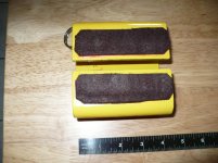
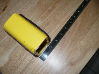
Frustrated with scarcity of suitable jack points on newer cars, I made this jack pad from a piece of 4 x 2x 1/4 wall rectangular steel tubing from where I used to work. I had it cut to a 4" length and a 1/2" slot milled down the center to accept the pinch seam.
It has slowly evolved, kind of odd looking and is bound to get a few chuckles but it does work nicely and preserves the pinch seam. A few notes are as follows:
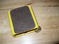
1) the pads that contact the underbody and the jack saddle are hard felt with adhesive backing. The bottom used to have coarse sandpaper glued to it to grip my jacks rubber saddle pad but since went to felt.
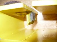
2) there is a rare earth magnet epoxied to the L bracket pop riveted adjacent to the slot. It holds the pad to the pinch seam while the jack is maneuvered underneath.
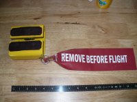
3) on my SUV it sits far under the rocker panel and I once forgot to remove it and drove around town for a day with the magnet still holding it on. Not wanting to lose it , or worse, having it come off at highway speed and bounce through somebody's windshield, I painted it bright yellow and added (harkening back to my old U.S. Navy aviation days) a red flag that hangs down to ground level. Pictures attached.
It has slowly evolved, kind of odd looking and is bound to get a few chuckles but it does work nicely and preserves the pinch seam. A few notes are as follows:
1) the pads that contact the underbody and the jack saddle are hard felt with adhesive backing. The bottom used to have coarse sandpaper glued to it to grip my jacks rubber saddle pad but since went to felt.
2) there is a rare earth magnet epoxied to the L bracket pop riveted adjacent to the slot. It holds the pad to the pinch seam while the jack is maneuvered underneath.
3) on my SUV it sits far under the rocker panel and I once forgot to remove it and drove around town for a day with the magnet still holding it on. Not wanting to lose it , or worse, having it come off at highway speed and bounce through somebody's windshield, I painted it bright yellow and added (harkening back to my old U.S. Navy aviation days) a red flag that hangs down to ground level. Pictures attached.