To avoid these ads, REGISTER NOW!

Ingersoll rand t30 wiring

Cameronlunz12

Member
Joined
Mar 27, 2021
Messages
20
Location
Lakewood ny
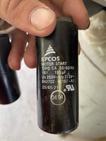
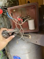
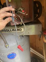
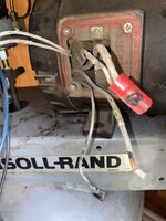
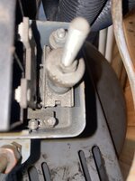
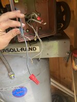
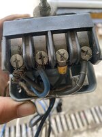
I have an ingersoll rand t30 air compressor with a single phase weg 00518os1ccd184t electric motor on it. I ordered a new motor start capacitor and when I moved the air compressor to my house the wires running from the 3 capacitors disconnected from each capacitor and the wires going to the pressure kill switch. I haven’t been able to find out any wiring diagrams or pictures that’ll help me wire it back up so any help would be appreciated. I will get a picture of what’s left of the wiring tonight
 

Attachments

  • AB1F921A-6FA1-4BB8-B6E2-942DDEFCE17A.jpeg
    AB1F921A-6FA1-4BB8-B6E2-942DDEFCE17A.jpeg
    485.2 KB · Views: 47
  • F7B3F657-FDB1-46D1-B628-6F0B561E8571.jpeg
    F7B3F657-FDB1-46D1-B628-6F0B561E8571.jpeg
    202.5 KB · Views: 36
  • 9F6F17DD-22D2-4AC5-B32B-D1292FE5147F.jpeg
    9F6F17DD-22D2-4AC5-B32B-D1292FE5147F.jpeg
    236.5 KB · Views: 32
  • D4A0433E-8D59-47F4-971E-AFD649565FB8.jpeg
    D4A0433E-8D59-47F4-971E-AFD649565FB8.jpeg
    296.8 KB · Views: 31
  • E45799D0-9288-40E6-96F2-5F8A8559DCB6.jpeg
    E45799D0-9288-40E6-96F2-5F8A8559DCB6.jpeg
    389.3 KB · Views: 40
  • F8D81A97-B570-4D5D-B11E-755BEF8729E1.jpeg
    F8D81A97-B570-4D5D-B11E-755BEF8729E1.jpeg
    269 KB · Views: 57
To avoid these ads, REGISTER NOW!
OP
C

Cameronlunz12

Member
Joined
Mar 27, 2021
Messages
20
Location
Lakewood ny
That’s all I’ve got
 

Attachments

  • 74B628D7-4D9A-4E27-A0D1-2F55A33CC316.jpeg
    74B628D7-4D9A-4E27-A0D1-2F55A33CC316.jpeg
    328.3 KB · Views: 49
  • 65A12B5E-B870-4AD3-A5A8-924BAB4B1AB3.jpeg
    65A12B5E-B870-4AD3-A5A8-924BAB4B1AB3.jpeg
    298.1 KB · Views: 44

justsam

Well-known member
Joined
Aug 20, 2010
Messages
1,268
Location
Penngrove, California
Looks to me like the two longer white leads, one has an insulated flag connector, go to the two start caps that are wired in parallel. Looks like the run cap has at least one wire on it, it only needs one more which I suspect it is the shorter white wire shown, with the tab connector. Not sure what is going on with the wire nut and what looks like some blue sheath cat 5 cable?

Need to confirm at some point that the start circuit in the motor is cutting out the start caps once running, or you will be replacing them again.
 
OP
C

Cameronlunz12

Member
Joined
Mar 27, 2021
Messages
20
Location
Lakewood ny
Okay so the longer white wire with the black insulated flag connector goes to the two capacitors that are wired parallel, and the short white wire with the connector goes to the white capacitor and the blue wire into the wire nut? But then that leaves the longer wire with the tab connector and the white wire that looks like it got cut? But I would assume they were working, I haven’t seen it run yet because I got it for free
 
To avoid these ads, REGISTER NOW!

justsam

Well-known member
Joined
Aug 20, 2010
Messages
1,268
Location
Penngrove, California
The wires for the start and run capacitors should ONLY be coming from the motor itself, nothing from the pressure switch. The box you show with the capacitors in it, did it have a front? Is it possible a switch was mounted to the front, or the 240VAC came in there? What is the type of wire with the blue sheath or is it tape? Where is it coming from? If not from the motor itself, it has nothing to do with the capacitors. There should be 2 hot leads and hopefully a ground coming into the pressure switch, and 2 hot leads and ground,, leaving the pressure switch and going to the motor.
 
Last edited:
OP
C

Cameronlunz12

Member
Joined
Mar 27, 2021
Messages
20
Location
Lakewood ny
Okay. The blue wire goes to the pressure switch. There was no cover when I got it, but anything I find online for new motors that match the model Number doesn’t have the switch on the cover. I wil get that conduit pulled off later to get a better view to trace the wires
 

justsam

Well-known member
Joined
Aug 20, 2010
Messages
1,268
Location
Penngrove, California
Do not over think this. These are very simple, reliable compressors. I have had one in service for close to 15 years. no issues. I have never seen one with any box mounted on them for the capacitors. The one I have, and others I have seen have a Dayton motor, with capacitors mounted on top of the motor. The only wiring is power into the pressure switch, and power out of the pressure switch going directly to the motor. Has this motor been replaced? Does the motor on it now have any thermal protection, e.g., a reset button on the motor?
 
OP
C

Cameronlunz12

Member
Joined
Mar 27, 2021
Messages
20
Location
Lakewood ny
It might have been replaced at some point, but not since I’ve owned it. But not that I know of there’s no reset button or anything on the motor
 
OP
C

Cameronlunz12

Member
Joined
Mar 27, 2021
Messages
20
Location
Lakewood ny
I pulled the box of the motor to see where the individual wires go. I see the blue and black wire coming from the pressure switch are both power wires, and the motor must get its ground through the tank. I’m assuming the thicker white wires going into the motor are both power wires, and all the thinner ones are for the capacitors. Does it matter which tab on the capacitors that the wires get plugged into? Because they aren’t labeled
 

Attachments

  • 84FFF693-6344-45B3-B3A9-63FDC7992480.jpeg
    84FFF693-6344-45B3-B3A9-63FDC7992480.jpeg
    234 KB · Views: 23
  • FAB2DABF-4B0C-4E40-AA8A-47A022AED3FE.jpeg
    FAB2DABF-4B0C-4E40-AA8A-47A022AED3FE.jpeg
    259 KB · Views: 16
  • 62DFC718-4E23-4C8F-B9F3-804467D79E34.jpeg
    62DFC718-4E23-4C8F-B9F3-804467D79E34.jpeg
    332.1 KB · Views: 15
  • EE56DC8D-97E9-4831-8654-73F51F09DF6C.jpeg
    EE56DC8D-97E9-4831-8654-73F51F09DF6C.jpeg
    272.3 KB · Views: 11
  • 7AE05AC6-D688-4B2F-9EA9-55BFE97DA71A.jpeg
    7AE05AC6-D688-4B2F-9EA9-55BFE97DA71A.jpeg
    208 KB · Views: 11
  • 7E4865C0-F288-4820-86C8-FA9A52AEF5FE.jpeg
    7E4865C0-F288-4820-86C8-FA9A52AEF5FE.jpeg
    206.1 KB · Views: 11
  • 7EB2948E-2AD0-4622-A4F7-BB9925E7B72F.jpeg
    7EB2948E-2AD0-4622-A4F7-BB9925E7B72F.jpeg
    346.1 KB · Views: 15
  • BB75EC30-E891-4D66-85B9-AA7B5F85CC1D.jpeg
    BB75EC30-E891-4D66-85B9-AA7B5F85CC1D.jpeg
    248.5 KB · Views: 14
  • 4A5F6E88-28BD-4151-86C1-3D4F0F5A7F22.jpeg
    4A5F6E88-28BD-4151-86C1-3D4F0F5A7F22.jpeg
    200.2 KB · Views: 14
  • A32ADF27-2BD3-40CC-838C-3D783302EADD.jpeg
    A32ADF27-2BD3-40CC-838C-3D783302EADD.jpeg
    293.5 KB · Views: 16
OP
C

Cameronlunz12

Member
Joined
Mar 27, 2021
Messages
20
Location
Lakewood ny
The last of the pictures I took
 

Attachments

  • DE344BB1-5416-45EC-9D03-5A98F8CA3960.jpeg
    DE344BB1-5416-45EC-9D03-5A98F8CA3960.jpeg
    234 KB · Views: 14
  • 07FC7C15-65C2-4E83-BE87-7DD427178671.jpeg
    07FC7C15-65C2-4E83-BE87-7DD427178671.jpeg
    272.5 KB · Views: 15

aprilsfool

Member
Joined
May 8, 2022
Messages
7
I know this was a couple of years ago, i was curious if you got this dude up and working? I have the same compressor, mine has the motor that came on it, it looks like someone had problems and bypassed the contactor and decided to let the pressure switch take all the load, mine has a different motor, I would reccommend putting a magnetic contactor on it. Let your pressure switch run the coil of the contact not load of the motor. That’s a hell of a deal if someone gave you that. It took me years to be able to afford to get a compressor like this.
 
To avoid these ads, REGISTER NOW!
Top Bottom