To avoid these ads, REGISTER NOW!

Wiring a Dayton overhead gas heater

lynnbilodeau

Well-known member
Joined
Jun 4, 2013
Messages
813
Location
Oklahoma
Have a used Dayton overhead gas heater that I need to wire.

Don’t laugh at my illustrations or terminology; I am neither an electrician, nor an HVAC expert.

First pic is my crude drawing of all the wires coming into or out of the J-box on the back of the unit.

Second pic is the junction box, with a transformer tied off to the side.

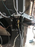
Third pic is what I will call the control box with the gas valve above it.

I have already run the T-stat wires (red and white) although they are not hooked up yet. But, clearly, I just need to connect them to the red and white wires at the gas valve.

Also, there are two (2) black wires already connected from the transformer to the gas valve.

At the top of the J-box, I have (surprise) Black, White and Ground coming in for power. Yes, the power is OFF until I get everything correctly connected.

Coming in the back of the unit is a three wire yellow cord. One of the three wires has red stripes, one has black stripes, and the middle wire has no stripes.

The back side of the transformer (which will be screwed to the J-box) has a black wire and a white wire. The black wire is already connected to the yellow / red stripe wire. The white wire is not connected to anything.

The two wires coming in from the fan are hot hooked up.

I also have a 6 inch pigtail ground to the back of the J-box that is currently not hooked up.

In short (no pun intended), assuming the black transformer wire Is correctly connected to the Yellow/Red wire, the wires I need to connect in the J-box are:

Three power wires.

The Yellow (middle wire) to the controller.

The Yellow/ black wire to the controller.

Ground.

White wire on the transformer.

Black and white to the fan.

Obviously, after I make all connections, the transformer gets attached to the J-box as the cover with the word “LINE” on the inside.Wires.jpgbox.jpgcontrol.jpg
 
To avoid these ads, REGISTER NOW!
OP
L

lynnbilodeau

Well-known member
Joined
Jun 4, 2013
Messages
813
Location
Oklahoma
Just realized I should have posted in the HVAC section. Mods, please feel free to move it. Not having a good day.
 

PoorUB

Well-known member
Joined
Mar 29, 2021
Messages
12,004
Location
Fargo, ND
I would be surprised if Grainger had any information on that heater. It has to be 40 years old!
 
OP
L

lynnbilodeau

Well-known member
Joined
Jun 4, 2013
Messages
813
Location
Oklahoma
Here is the data plate. I found several sources for install manuals, but every one was blocked as being "unsafe". Second pic is from a generic install manual that covers multiple models.
ModelNo.jpgWiringDiagram.jpg
 
OP
L

lynnbilodeau

Well-known member
Joined
Jun 4, 2013
Messages
813
Location
Oklahoma
Looks to me, with my limited AC electrical background, that my line in hot (black) wire connects to the black wire on the transformer “line” side, as well as to the yellow wire with the red stripe, which in turn goes to the controller.

The common (white) line coming in connects to the white wire going to the fan (M2) as well as to the white wire on the “line” side of the transformer. Not sure if my unit has an M1 (forced exhaust fan) but if it does, it too is connected white wire to white wire.

The black wire from the fan motor would then go to the yellow wire with black strip that goes to the controller (shown in the diagram as “heat” terminal on the controller.

That just leaves the middle yellow wire with no stripe, which I would assume is ground, and would be connected to my 6 inch pigtail in the J-box and the ground coming in with my power lines.


Am I way off base here? Someone on this site has certainly hooked up heaters like this. I got it practically for free. Nothing rusted out, and the fan turns uber freely. Seems a shame to not give it a go. I am fine spending $1300 on a new one if I must. I have a Modine in my garage at the house, and it is ancient, but heats the 2500 foot garage up from 40 degrees to 70 in about 15 minutes on a really cold day. If not exposed to the elements, these old units seem to last decades.

Once again, any input is greatly appreciated.
 

mrobins297aaa

Well-known member
Joined
Sep 20, 2010
Messages
3,283
Location
south east michigan
Did you figure it out yet?
the main components are the transformer, thermostat and the gas valve on the 24 volt side.
the wiring would be as follows: R on trans former to r on thermostat to coil side of gas valve and from the other side of gas valve to the other side of the transformer.
see if that makes sense

without seeing all the components, it looks like you have a 120v safety
take the cover off that box below the gas valve so we can see what it looks like on the inside
 

mrobins297aaa

Well-known member
Joined
Sep 20, 2010
Messages
3,283
Location
south east michigan
I think your right about the yellow wires just got to make sure get them in the right order.
all the 120v wires in the messy drawing are your yellow wiresIMG_20210913_0001.jpg
 
To avoid these ads, REGISTER NOW!

PoorUB

Well-known member
Joined
Mar 29, 2021
Messages
12,004
Location
Fargo, ND
The wiring diagram in post #6 has zero to do with the heater you have. It is for a fairly current model, so disregard it.

Those yellow wires got to a safety and a fan switch, at least I would guess. We need to sort them out.
 

PoorUB

Well-known member
Joined
Mar 29, 2021
Messages
12,004
Location
Fargo, ND
I am certain there is two "limit" or snap switches under the cover, connected to the yellow wires. One of then turns on the fan when the heat exchanger gets warm. The other shuts off the gas if the heat exchanger gets too hot. Which is which? I don't know. If you can read any printing on then the lower temperature one should be the fan switch and it should be open at room them. The other is a high temp limit and it should be closed at room temp.

The transformer needs to be powered all the time. One of the 120 volt legs might go through the high limit. I am assuming if you look at the limit and fan switch one yellow wire connects to both, this will connect to 120 volt incoming power. the voltage goes through the one to the transformer. the other goes through the other limit to the fan motor.

When the heater gets a call for heat the 24 volt side powers the gas valve. The gas valve opens, and the burner lights. The burner will run for 5 -10 seconds until the one snap switch gets warm enough and started the fan motor. If the fan motor fails the other snap switch gets to hot and opens up, and drops the power to the trans former and kills the low voltage and the gas valve shuts off. The fan will continue to run until the the temp limit cools down and resets, (unless it is a manual reset) and then it closes, or you reset it and the gas valve opens and we start all over again.
 

PoorUB

Well-known member
Joined
Mar 29, 2021
Messages
12,004
Location
Fargo, ND
This my version. Keep in mind I have had a couple Crown Royals, but I think this is right.
 

Attachments

  • heater.jpg
    heater.jpg
    83.4 KB · Views: 71
  • Like
Reactions: D45
OP
L

lynnbilodeau

Well-known member
Joined
Jun 4, 2013
Messages
813
Location
Oklahoma
Here is the control panel with the cover off.

Am I on the right track in post #7 above?

Ready to hook it up and give it a go.
 

Attachments

  • Control2.jpg
    Control2.jpg
    421.8 KB · Views: 59

mrobins297aaa

Well-known member
Joined
Sep 20, 2010
Messages
3,283
Location
south east michigan
ok this is my best guess without seeing more of the whole picture.
The disc on the bottom is the 120v safety/limit.
The yellow with the red strip goes to the Black at the junction box on the side of the unit it's the main feed. The power goes thru that disc to feed everything else, if you have a way to check continuity that disc should be closed .

the yellow wire on the other side of the disc goes to the 120v black on the transformer.

The top yellow wire in the picture goes to the black on the fan.
That switch that it's connected to looks like a combination relay, the two black wires coming from the gas valve are 24volts with a coil connected inside the switch between. The Black wire coming off of the safety is providing the 120v power for the fan when the 24 volt coil gets power from somewhere up there on the gas valve it closes the switch and connects the 120v from the black to the yellow that goes to the fan.
take a look at this and see it it makes any sense as to the wiring you already have, it's really hard to figure this out when you really can't see the whole picture.

Move that blk wire away from the relay so we can see the numbers on the relay (I can see numbers 1 and 3) and see if they show a coil between the 24v on the relay
take a better picture of the wiring on the gas valve
 

mrobins297aaa

Well-known member
Joined
Sep 20, 2010
Messages
3,283
Location
south east michigan
All the white wires, from the fan and transformer connect to the white at the junction box.
none of those yellow wires are ground.
on the relay between #1 and #3 there should be no continuity with the power off.
on the relay between the two 24v connections there should be some ohms of resistance, if you have a way to measure it.
 

nadogail

Well-known member
Joined
Jan 23, 2009
Messages
32,332
Location
Coronado, CA
Dayton is a Private Label used by WW Grainger. A very well respected company who I have found to provide excellent customer service. If they are telling you the heater is unsafe, you can bank on their word. Many things we liked 40 years ago are no longer considered safe by current standards.
Time to consider the age and physical condition of the heater. Heat exchangers fatigue and crack over time from repeated thermal cycling. Have your heater inspected by a professional and make sure that your CO alarm batteries are good. We don’t want to hear about your death from a defective heater.
 
OP
L

lynnbilodeau

Well-known member
Joined
Jun 4, 2013
Messages
813
Location
Oklahoma
Can't believe I never followed up. The heater works great. I had the gas line run in 2022, then had my HVAC guy look at my wiring. Gas company came out an inspected the vent (through the roof) and the wiring, as well as the gas line plumbing. Fired right up.
 
To avoid these ads, REGISTER NOW!
Top Bottom