To avoid these ads, REGISTER NOW!

Electrical motor help (yes, I've searched)

Zeke

Well-known member
Joined
Aug 13, 2009
Messages
17,176
Location
Long Beach CA, the sewer by the sea.
I may have missed a discussion on this and if so, I apologize. Any links will be helpful and I'll go from there.

Meanwhile, the subject motor is a WWII era GE Model 5... (OK, I know it rotates) KC 634B50, or O, plus an 8. Not much comes up under that nomenclature.

The gist if it is that this is a 1/2 HP dual voltage, reversible, capacitor start lathe motor that I pretty well know came with a 1944 South Bend lathe (horizontal drive)

Now to the problem, I can't wire it up. It might have been wired for 240v and using a standard 5-15R receptacle. I wouldn't put it past the guy that had this, but after turning the motor on forward and reverse, I unplugged it and moved it home. So, there is a slight chance that might be part of my difficulties because I intend to use 20 A 120v power though the existing Furnace brand drum switch.

I probably have the drum switch figured out and I don't think it was wired correctly to begin with. No matter, I screwed up labeling when disassembling the old cord (a 6-wire beast with all black wires).

AFA the motor is concerned, it too has all black wires coming out of the frame, BUT they are banded in brass rings, T-1 thru T-6. That's where I am now, trying to find the start circuit, the run circuit and the reverse wiring. Last I remember doing last night (tired) was running 120v directly to the motor and I think I had 1,2 &5 in one bundle and 3,4 & 6 in the other and it would spin with help but go about 100 RPM. I didn't leave it at that long at all. Any other combination suggested on YouTube, etc., came up crickets, but no smoke, thankfully.

Most people wire the power cord into the drum switch but this originally had the power in the small box on the side of the motor. It was too crowded being that the neutral ran up the 6-wire cable and there were all of 6 wire nuts in that little box.

To recap; 6 wires in the motor, all black but labeled and no idea what's what. Additionally I probably need to check the start cap and I do have a MM with that function. But have no idea which wires go to the cap. BTW, I'm using 1/2" Sealtight conduit and individual 12 ga. stranded wires and a larger j-box on the motor.

Where to start? Thanks.

Oh, and everyone always asks for pics on discussions I've read. There are 6 black wires — nothing to look at.
 
To avoid these ads, REGISTER NOW!
OP
Z

Zeke

Well-known member
Joined
Aug 13, 2009
Messages
17,176
Location
Long Beach CA, the sewer by the sea.
Nothing external and nothing on the access to the terminals inside the frame. Well, I can only see one and I can see 2 wires leading to the cap. But if I gently wiggle one, nothing seems to move coming out of the motor.

When it comes to motors, I'm not well educated. I'm not too stupid either. If I found a wiring diagram on the motor, I'd probably know not to spend 10 minutes composing a question, giving all of the information that I can find.

If it isn't relatively easy to figure this out, I'll simply use another motor. I shouldn't have spent good money on a machine rated 5L belt for this set up. That WAS stupid.
 
OP
Z

Zeke

Well-known member
Joined
Aug 13, 2009
Messages
17,176
Location
Long Beach CA, the sewer by the sea.
99% of articles talk about single rotation motors, as does that one. But thanks anyway.
I want to admit that this old motor was full of metal chips due to the previous owner apparently using an air hose to clean off this lathe. I also used air to dislodge a handful of chips. I'm sure I managed to short it out.

I have no choice but to replace it. Besides, no one seems to understand these old motors. I don't, so it's hitting the scrap pile.
 

Bert_

Well-known member
Joined
Dec 24, 2016
Messages
9,775
Location
NW Iowa
Have you pulled an end bell off yet? Usually a motor with shorted windings runs hot and trips the overload.

Will the motor take off if you give it a spin by hand?
 
OP
Z

Zeke

Well-known member
Joined
Aug 13, 2009
Messages
17,176
Location
Long Beach CA, the sewer by the sea.
No tag on the motor?

Have you pulled an end bell off yet? Usually a motor with shorted windings runs hot and trips the overload.

Will the motor take off if you give it a spin by hand?
Good question. No, I can't get it to run more than 100 (prox) RPM by starting it by hand. Seems like it will go in either direction too. I guess when I said 'shorted' I misspoke. There has been no drama. The only value to a motor like this is the so called "instant reverse" feature built in to an old lathe motor. It is said that it is built to take that type of punishment although I myself would tend to wait for spin down before reversing. Sounds like a good way to spin a chuck off.
 

rlitman

Well-known member
Joined
Oct 18, 2010
Messages
24,662
Location
Long Island
99% of articles talk about single rotation motors, as does that one. But thanks anyway.
I want to admit that this old motor was full of metal chips due to the previous owner apparently using an air hose to clean off this lathe. I also used air to dislodge a handful of chips. I'm sure I managed to short it out.

I have no choice but to replace it. Besides, no one seems to understand these old motors. I don't, so it's hitting the scrap pile.
There are motor rebuild shops by me, and hopefully by you. It's worth at least taking it there for a diagnosis.

The windings can be identified using an ohm meter. Drum switches are pretty complicated, but not so bad once you find a wiring diagram.
 

Bert_

Well-known member
Joined
Dec 24, 2016
Messages
9,775
Location
NW Iowa
Have you wired it
L1-1,3,6
L2-2,4,5

Except for substituting 6 for 8 that's standard low voltage wiring for most dual voltage single phase motors.

Standard labeling for the start winding would be 5&8 today. I'm guessing they might have used 5&6 on your motor. 1&2 would be one run winding, 3&4 the second run winding. Motors aren't that complicated and 6 lead single phase motors are common.

The wiring you tried in post #1 may have had no power to either run winding.
 
Last edited:
OP
Z

Zeke

Well-known member
Joined
Aug 13, 2009
Messages
17,176
Location
Long Beach CA, the sewer by the sea.
Yes, I have wired it that way. In fact, I wired it that way with a power cord and also reversed the 5 and 6, (or 5 and and 8 in modern terms). This is what gets the motor to hum and by hand turning will go slowly.

What I don't understand about your scheme is why 1-1 and 2-2 are repeated. What am I missing there?
 

Bert_

Well-known member
Joined
Dec 24, 2016
Messages
9,775
Location
NW Iowa
Yes, I have wired it that way. In fact, I wired it that way with a power cord and also reversed the 5 and 6, (or 5 and and 8 in modern terms). This is what gets the motor to hum and by hand turning will go slowly.

What I don't understand about your scheme is why 1-1 and 2-2 are repeated. What am I missing there?
L1 and L2 are the line wires. L1 connects to T1,T3,T6
 

Bert_

Well-known member
Joined
Dec 24, 2016
Messages
9,775
Location
NW Iowa
Try to identify the motor windings one at a time. Grab a meter set to ohms and start checking between the motor leads. Check from T1 to T2,T3,T4 and so on. Post which wires have continuity.

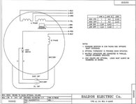
The motor is wired something like this, we just don't know the terminals.
baldorD90L_zps21b916f7.jpg
 
Last edited:
OP
Z

Zeke

Well-known member
Joined
Aug 13, 2009
Messages
17,176
Location
Long Beach CA, the sewer by the sea.
OK, I follow now. L1 = hot and L2 = neutral. I will do that meter test now. As I understand it, the motor winding continuity will register in Ohms as will the start circuit, but the start circuit will move the numbers as you hold the leads, and tends to have a higher resistance.
 
OP
Z

Zeke

Well-known member
Joined
Aug 13, 2009
Messages
17,176
Location
Long Beach CA, the sewer by the sea.
1-2=0
1-3=2.7
1-4=0
1-5=0
1-6=0

2-3=0
2-4=2.4
2-5=0
2-6=0

So as to not be redundant, the following are
3-4=0
3-5=0
3-6= flashed 30+ Ohms and went immediately to O.L or zero

5-6=0
5-4=0
I think that covers the possibilities. At least it paints a picture.
 

RPH

Well-known member
Joined
Dec 17, 2006
Messages
4,190
Location
Michigan Thumb
3-6= flashed 30+ Ohms and went immediately to O.L or zero

This should be the start winding. The capacitor will block the meter dc voltage. So an initial charge up the capacitor shows continuity until the cap is full. Verify start switch operation and viable capacitors.
 

Sumboodie

Well-known member
Joined
Mar 20, 2021
Messages
10,742
Location
AK
240v 5r15 receptacles were common in farm buildings where I grew up.

A 1960s Sears Roebuck air compressor works really quick when plugged into the wrong outlet. My Dad hear it spool.up from outside and came running in, knowing exactly what I'd done.

Usually they were red to denote it being 240v.
 
To avoid these ads, REGISTER NOW!

Bert_

Well-known member
Joined
Dec 24, 2016
Messages
9,775
Location
NW Iowa
1-2=0
1-3=2.7
1-4=0
1-5=0
1-6=0

2-3=0
2-4=2.4
2-5=0
2-6=0

So as to not be redundant, the following are
3-4=0
3-5=0
3-6= flashed 30+ Ohms and went immediately to O.L or zero

5-6=0
5-4=0
I think that covers the possibilities. At least it paints a picture.
2.7 and 2.4 are close enough that I'm going to say those are the run windings.

I'd say forget about the start winding for the moment and try
L1-t1,t2
L2-t3,t4
Or
L1-t1,t4
L2-t3,t2

What you're trying to do is get the run windings phased correctly. If they are backwards they will fight each other.

Since we are just connecting the run windings you will have to give it a spin by hand when you apply power. Once it's spinning it should take off and run normally if it's right.

Normally when your meter shows no continuity you would say the circuit is open. Saying zero implies no resistance, like touching the meter leads together
 
Last edited:
OP
Z

Zeke

Well-known member
Joined
Aug 13, 2009
Messages
17,176
Location
Long Beach CA, the sewer by the sea.
Bert, thanks for the nomenclature clarification. As I said, I'm not educated WRT to motors (and controls). I have the bell end off. It's dirty in there but no stink. However, the cap had to come off to get the end off because the board that contacts the centrifugal switch is captured by the ball bearing. I'm not sure I need to go any further at this point because the cap reads zero microfarads. If that's the same as 'open' then it's open. Whatever, it's not doing anything, so there's that.

What bothers me is that I wasn't able to spin the motor to the point that it would catch. I know I can't spin it fast enough for the centrifugal switch to open and I can't let it sit there and start to cook.

So, if an old Mallory cap is available and not too expensive, I'll start back with that. Meanwhile I can shrink wrap and relabel the 6 leads. The ones from the cap to the board do not look too good, and I might have to splice in a section since one goes directly into the windings.

So. I'll be back in a week or so with results on sourcing a cap, or just another motor. I did find a 1/3 HP motor already with a reversing switch that I had culled out of an old commercial paper shredder. That might put the lathe in service for the time being.

Thanks to all of you.
 
OP
Z

Zeke

Well-known member
Joined
Aug 13, 2009
Messages
17,176
Location
Long Beach CA, the sewer by the sea.
BTW, that would be Mallory or equivalent. Have to find the specs first.

Edit: well, under the cardboard liner is all the printing. Says 20 starts an hour. Must not be for a lathe motor.
It's old, says 110v. 400-450 MFD

I think I saw that regardless of line voltage, (120 or 240) that the capacitor will be rated at 120v because of how the internal wiring deals with this. Wait for Monday when I can call someone that sells these.
 
Last edited:

Bert_

Well-known member
Joined
Dec 24, 2016
Messages
9,775
Location
NW Iowa
Bert, thanks for the nomenclature clarification. As I said, I'm not educated WRT to motors (and controls). I have the bell end off. It's dirty in there but no stink. However, the cap had to come off to get the end off because the board that contacts the centrifugal switch is captured by the ball bearing. I'm not sure I need to go any further at this point because the cap reads zero microfarads. If that's the same as 'open' then it's open. Whatever, it's not doing anything, so there's that.

What bothers me is that I wasn't able to spin the motor to the point that it would catch. I know I can't spin it fast enough for the centrifugal switch to open and I can't let it sit there and start to cook.

So, if an old Mallory cap is available and not too expensive, I'll start back with that. Meanwhile I can shrink wrap and relabel the 6 leads. The ones from the cap to the board do not look too good, and I might have to splice in a section since one goes directly into the windings.

So. I'll be back in a week or so with results on sourcing a cap, or just another motor. I did find a 1/3 HP motor already with a reversing switch that I had culled out of an old commercial paper shredder. That might put the lathe in service for the time being.

Thanks to all of you.
If it won't run when you spin it by hand the capacitor is not the problem. It might be A problem but there are others.

At this point I think the most likely thing is to try what I suggested in the last post. If the run windings are connected out of phase the motor isn't going to run
 

American Locomotive

Well-known member
Joined
Jan 8, 2017
Messages
11,013
Location
Rhode Island
BTW, that would be Mallory or equivalent. Have to find the specs first.

Edit: well, under the cardboard liner is all the printing. Says 20 starts an hour. Must not be for a lathe motor.
It's old, says 110v. 400-450 MFD

I think I saw that regardless of line voltage, (120 or 240) that the capacitor will be rated at 120v because of how the internal wiring deals with this. Wait for Monday when I can call someone that sells these.
Starts per hour are usually defined with a certain inertial load. Starting a big fan, or a very heavy flywheel, for example. Lathes usually aren't that.

A lot of motors really need to get spinning very fast by hand to "catch" if their start circuit is bad. And as mentioned, if you connect the run windings "anti-parallel", the two windings will be fighting each other. If the motor worked when you bought it, and it hasn't been used since, it's very unlikely it magically went bad.

Either you're not wiring it correctly, or the start switch is a bit gummy/dirty.
 

wyliesdiesels

Well-known member
Joined
Aug 14, 2012
Messages
20,073
Location
Modesto, CA
open
meter shows O.L same as when I turn it to Ohms. Touching the leads says 0.000, so I see why you ask.

In response to Bert's question I was reporting zero continuity.
O.L (infinite) and 0 ohms are not the same so not a good idea to use O.L Better to use infinite
 

Bert_

Well-known member
Joined
Dec 24, 2016
Messages
9,775
Location
NW Iowa
A lot of motors really need to get spinning very fast by hand to "catch" if their start circuit is bad.
That hasn't been my experience at all. I would say that most just need a gentle spin, especially with no load.

I wouldn't recommend it but I know several people who have motors that always get started this way. Plug it in, give the pulley a spin and it's running.
 
OP
Z

Zeke

Well-known member
Joined
Aug 13, 2009
Messages
17,176
Location
Long Beach CA, the sewer by the sea.
post a clear photo of the tag on it. Where you are getting the model and serial on it from.
Just a small drive screw mounted data plate that gives the usual info like voltage/RPM/HP/Model#/brand. There isn't even a serial no. on it. I found a number stamped on the case under the cap mount.

At this point I have separated the ends from the center section, cleaned and greased the roller bearings, cleaned the contacts for the centrifugal switch and put it back together sans the cap. Still good readings on 1-3 and 2-4 but with 120v applied to just those 2 pairs, not even a hum. So to get a him and some movement, I have to add in 5 and 6 which ever way.

Any chance the power originally was wired in through 5 or 6 and either 1-3 or 2-4 were not directly connected to the power source? I mean, logically, I'm with Bert. It worked when I bought it. I took it apart to paint the countershaft frame as well as everything else. All new felts, etc. Somewhere I lost track of the wiring even though I tagged everything. Now I've given up on any of my identifications and stripped all the ID off. Starting (no pun) from scratch.

I think from remnants of my ID that no. 1 was on one pole of the drum switch which means to me that 1-3 were not always tied together.

Oh well, I finally fried it.
 

FredWanaker

Well-known member
Joined
Mar 27, 2021
Messages
1,470
Location
NorCal
well, without something more visual to go on like a shot of the tag on it and the actual motor, I sure can't do anymore searches that might help.
 

Bert_

Well-known member
Joined
Dec 24, 2016
Messages
9,775
Location
NW Iowa
For some reason you don't want to post any pictures but just humor me. Post a couple.

A good clear picture with the end bell off would have been really great.
 

American Locomotive

Well-known member
Joined
Jan 8, 2017
Messages
11,013
Location
Rhode Island
At this point I have separated the ends from the center section, cleaned and greased the roller bearings, cleaned the contacts for the centrifugal switch and put it back together sans the cap. Still good readings on 1-3 and 2-4 but with 120v applied to just those 2 pairs, not even a hum. So to get a him and some movement, I have to add in 5 and 6 which ever way.
If you're still measuring 2.4-2.7 ohms across 1-3 and 2-4, it HAS to hum when you plug it in. It has no choice. 2.4 ohms @ 120v will result in 50A of current. If you have 50A of current flowing through a coil, you WILL know about it. Either through it humming or smoke and fire erupting from somewhere after a few seconds.

I suspect you are still not connecting things correctly, and are actually just putting both sides of each run-winding on the same leg of power, which would result in nothing happening.

Edit: I just re-read your post.
1-3 CANNOT be tied together. Those wires are either end of the same coil. If you tie them together, it's the same thing as taking a loose piece of copper wire and connecting the ends to each other. Nothing will happen if you do that.

Let's ignore the starting wires for now:

1 and 2 need to be tied together and connected to L1
3 and 4 need to be tied together and connected to L2
Leave 5 and 6 disconnected for now

Wrap a rope around the motor's shaft a few turns (just enough so it grips the shaft firmly), apply power and give the rope a good yank. See if the motor starts. If it sits there and spins slowly without going anywhere, reconfigure the wiring as follows

1 and 4 tied together and connected to L1
2 and 3 tied together and connected to L2
5 and 6 disconnected

and then try again.
 
Last edited:
OP
Z

Zeke

Well-known member
Joined
Aug 13, 2009
Messages
17,176
Location
Long Beach CA, the sewer by the sea.
For Bert and others, I took it apart (again) just to show the pics. And I was wrong about the cap. As it won't do anything with the cap out, I put it back. It does read but low, and after powering it up, I thought I might see a small spark when I shorted it. No.

So here are your pics.
 

Attachments

  • IMG_0407[1].JPG
    IMG_0407[1].JPG
    227.1 KB · Views: 40
  • IMG_0408[1].JPG
    IMG_0408[1].JPG
    270 KB · Views: 37
  • IMG_0409[1].JPG
    IMG_0409[1].JPG
    269.3 KB · Views: 39
  • 100_0401[1].JPG
    100_0401[1].JPG
    336.8 KB · Views: 42

FredWanaker

Well-known member
Joined
Mar 27, 2021
Messages
1,470
Location
NorCal
 
To avoid these ads, REGISTER NOW!
Top Bottom