To avoid these ads, REGISTER NOW!

Puget Dude’s creations and fabrications (Random project thread.)

OP
P

PugetDude

ALLIANCE MEMBER
Joined
Mar 13, 2013
Messages
22,373
Location
Superstition Mountains, AZ
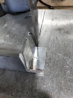
Worked on the two frame members at the rear of the chassis today. These ended up being the most difficult components to fab so far. Very tight bend radius, and they had to match the frame kickup where I bobbed the frame and tie into the bumper.
Ended up making them out of pie sections, too much material to cut out and kerf them. - and I was running out of 1-1/4” tubing so I didn’t have much extra to experiment with.
63622AD0-DC28-46D5-A1D4-9CDFF4DE3846.jpeg
Excuse the ugly welds, I deliberately poured a lot into the joints to ensure I had plenty to grind without excessively thinning the parent material.
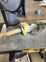
Took most of the excess off with the 2x72 belt grinder and then cleaned the rest up with a 40 grit flap disc.
176759E5-FCF8-4F4D-9C01-F3B3D476BCC0.jpeg
Got them matched up and cleaned up.
4970091E-2068-461E-B6D6-BACECD34B0A2.jpeg
Next step is to install them.
 
To avoid these ads, REGISTER NOW!

LXCam

ALLIANCE MEMBER
Joined
Apr 23, 2013
Messages
19,113
Location
AZ
Scott, does your belt grinder allow you to do slack belt grinding?. If it does get or make yourself a 1/2" wide 240 grit belt for blending the outside corners of what you made there. It'll make a huge difference for grinding the radius as the 1/2" wide belt (when slack) flexes and follows the inside curves without the belt edge cutting into the tube.

Looking good bud, glad to see your making a ton of progress.
 
OP
P

PugetDude

ALLIANCE MEMBER
Joined
Mar 13, 2013
Messages
22,373
Location
Superstition Mountains, AZ
Got these tacked in place. B34FDDB7-C320-4440-BEB4-4CF5D150C835.jpeg
Checked one last time that everything lined up the way I wanted and then started welding the tops and sides of all the joints. 95558E83-5836-4BA1-915F-4C6C636C7529.jpeg
Here’s where these will support the glass body 710BEA65-0EFF-4D5E-9F3B-EE3832B162DD.jpeg
These little pieces were way too much work, but they do fit really well. E8AD46E6-378A-4A03-AE35-60CBDF9ECBE5.jpeg
Also got the new 1/4” thick frame horns boxed and blended into the bumper, used 1/8”x 2” flat bar on the top side and 14 gauge inside skins.
I’ll finish boxing the underside when I flip the frame. 6C1267D3-D8A0-4C51-8823-255A546B54B9.jpeg

I grind way too much; can’t help myself.. probably comes from my early days working for a fab shop that built food-grade tanks and pressure vessels, welds were nearly always strip ground flush.
 
OP
P

PugetDude

ALLIANCE MEMBER
Joined
Mar 13, 2013
Messages
22,373
Location
Superstition Mountains, AZ
Scott, does your belt grinder allow you to do slack belt grinding?. If it does get or make yourself a 1/2" wide 240 grit belt for blending the outside corners of what you made there. It'll make a huge difference for grinding the radius as the 1/2" wide belt (when slack) flexes and follows the inside curves without the belt edge cutting into the tube.

Looking good bud, glad to see your making a ton of progress.
Thanks, Cam. I haven't tried the slack belt technique; suppose I could remove the backing platen and try it. On these I just hit the corners with a 2" Roloc 40 grit flap disc in the M12 die grinder. They're all going to be covered by the body, anyway.
 

Bears Fan

Well-known member
Joined
Jan 26, 2012
Messages
3,438
Location
Indiana
Awesome work! glad to see you staying motivated on the 32', with my attention span I would of moved on to a different project by now o_O

Those rear brackets and bumper look great! you should be able to use that rear bumper as a push truck at the local race track on Saturdays nights :ROFLMAO:

Keep the pictures rolling :thumbup: :thumbup:
 
OP
P

PugetDude

ALLIANCE MEMBER
Joined
Mar 13, 2013
Messages
22,373
Location
Superstition Mountains, AZ
Awesome work! glad to see you staying motivated on the 32', with my attention span I would of moved on to a different project by now o_O

Those rear brackets and bumper look great! you should be able to use that rear bumper as a push truck at the local race track on Saturdays nights :ROFLMAO:

Keep the pictures rolling :thumbup: :thumbup:

I like the look of a rolled rear pan on a ‘32 Roadster but also wanted a rear bumper.
 
OP
P

PugetDude

ALLIANCE MEMBER
Joined
Mar 13, 2013
Messages
22,373
Location
Superstition Mountains, AZ
Took a couple of days to work on the seat mounts. An older Chrysler minivan seat works great in a ‘32, bonus is I got the sliders as well as the seat for $40 at a salvage yard. 3EC16C34-03F5-45B9-8F05-6AFF18A6F805.jpeg
I cut the factory bases off as low as possible and added an angle iron base to them. FF5E0BB0-E9AF-487C-AED3-79427D865A8B.jpeg
In order to exponentially increase the level of difficulty and time required to install I elected make it flip forward and lock in place. This would give me access to the space behind the seat, I’m thinking it might be a good location for the fuse box.
Hinging the seat was no problem but the locking mechanism was going to take some time to figure out- very little room to work with on the slider framework and I didn’t want the latch mechanism to rattle around when I eventually get around to driving it.

Ended up mounting a couple of small Destaco push clamps, extending the rods, and building an indexing/locking frame that would allow the seat flip back down to the exact location every time so I could push the locking clamps in place. F2D71F79-FBF2-4A45-8AA3-1EAA9DEBF341.jpeg
Here’s what the latching end looks like in place on the body; this entire base frame will go inside the body, wanted to make frame mounts and make sure everything fits before I wrestle the body back on. 7C3D1D28-3C7A-43A7-B526-A6F106474B4D.jpeg2E9057A2-BC7A-4C54-8E37-869C4C05BE5B.jpeg
The locating pin lands in the v-block and provides exact registration for the locking rod in the nylon bushings. These were just 3/4” nylon bolts I drilled and reamed to fit the 1/2” cold rolled steel locking rods. If they turn out to be too wimpy I can make brass replacements later; they just thread into the 3/4”NC nuts that are welded into the seat locators.
These eliminated any metal-to-metal rattling. 6DEFDB57-4CA9-4F27-9F71-5C8CB40FD12E.jpeg

Still have the outboard seat belt mounts to figure out while I’m doing the frame fabrication, but getting close to pulling the engine and suspension and flipping the frame. Will probably do something similar to what I use for the seat mounts. These are just short pieces of 1-1/4” square tube, capped with a heavy 5/8” washer with a 1/2” nut welded underneath. 192AC928-BAFE-43C2-81C2-C210057A333A.jpeg

Here’s the completed frame bolted in place, slotted the holes to make it easy to install once the body goes on. 9CFAF757-410A-41AE-8A2E-54B0341BE886.jpeg


I’ll get a couple more pics when I get it all re-assembled and the seat bolted back on.
 
Last edited:

zmotorsports

ALLIANCE MEMBER
Joined
Oct 20, 2009
Messages
21,381
Location
Northern Utah
Great job on the rear supports Scott. Those turned out really clean and consistent.

Question, with the rear shocks being spaced out from the stringer by what looks like at least an inch or so, are you concerned about leverage on that upper shock bolt being in single shear?

Just a thought that maybe you could add another stringer parallel to the shock mount with a crush sleeve inserted which will allow you to mount the upper shock mount in double shear. I marked up a picture for reference.
shock2.jpg

Sorry, it's not the best sketch but hopefully you can see what I'm asking.
 
OP
P

PugetDude

ALLIANCE MEMBER
Joined
Mar 13, 2013
Messages
22,373
Location
Superstition Mountains, AZ
Mike, I have been thinking about that, too. That shock mounting tube with the bosses came with the car, the shock pads I welded to the Ford 8.8 rear axle are also in single shear with similar spacers - both use 5/8” grade 8 bolts. The coil overs are only 5/8” away from the axle tubes; don’t really have room to move them without making the spacers any longer than they are now. I have considered shortening the upper spacers to reduce the moment load on the bolt( could add another support to put them in double shear) but that would require lengthening the lower spacers on the axle to keep them on the same relative plane. Maybe weld the lower spacers to the mounts… or change them to a offset stud mount-don’t know if that would help or hinder the strength/suspension geometry.
 
OP
P

PugetDude

ALLIANCE MEMBER
Joined
Mar 13, 2013
Messages
22,373
Location
Superstition Mountains, AZ
Great job on the rear supports Scott. Those turned out really clean and consistent.

Question, with the rear shocks being spaced out from the stringer by what looks like at least an inch or so, are you concerned about leverage on that upper shock bolt being in single shear?


Just a thought that maybe you could add another stringer parallel to the shock mount with a crush sleeve inserted which will allow you to mount the upper shock mount in double shear. I marked up a picture for reference.
shock2.jpg

Sorry, it's not the best sketch but hopefully you can see what I'm asking.

Well Mike, you got me thinking… there’s not much I can do on the lower shock bolt but it’s attached to a really stout axle mount; the top was attached to a single piece of light gauge 1”x2” rectangular tubing, as you pointed out. That was what came with the pile of parts for the car but it doesn't mean it has to stay that way.
So,… off to buy more steel. Found a local welding shop that sold me a couple of sticks of tubing and angle for just a few bucks more than the big steel supplier halfway across town. At $5.00/gallon for gas that was a no-brainer.
First step was figuring out the crush tubes; I needed ~1” OD x5/8” ID. I had some 1/2” pipe that would have worked with a bit of reaming to take out the weld seam- and then it dawned on me that I could just cut the unused bosses off the existing crossmember and use them.0D2898A8-F671-4440-9DD8-C87D8B962EDE.jpeg
I cut them off with a cutoff wheel in the angle grinder and got them tack welded into a 1” diameter through hole I cut in the heavy wall rectangular tubing with an annular cutter I bought on Amazon last year. Pretty unimpressed with the cutter but It got it done. Had to be careful not to get into the bore with the weld.20AF84AD-F0E1-4023-AA29-6C3BC7770C28.jpeg
Cleaned them up with a grinder and a countersink so the shocks would sit flat when i bolted them in place. . “Precision honed” the bore with a sanding band in the M12 rotary tool.;) 9ACB7726-C2FE-4F42-A765-2F74EA6B9C21.jpeg
After these were done I fit them up in the frame and made sure I could get the coil-overs in place ( used a 5/8” flat washer as a shim) and then tacked it all together. C6687C9F-5E29-4842-99FF-A56F743457A9.jpeg
Final step was welding the tops and sides; bottom will be welded when I flip the frame.
E50F24DB-B3CC-447A-8C63-B1042D743C9F.jpeg827CEA33-AB0A-4CAC-AD43-A7DD0105760B.jpeg
This should help spread the load on the top shock bolt and provide a load path to the adjacent frame members. It was better to address it now rather than have it fail after the frame is painted and the car assembled. I have it back together with 2 pieces of 5/8" all-thread for now, will use new 5/8 x6" Grade 5 or 8 bolts for final asembly.
Looks a lot like Honch's photshop photo in post #254 above - but I did take the opportunity while I was cutting and welding to shorten the shock bosses by 3/8" to give me a little more clearance between the coil overs and the axle.
Thanks for the suggestions!


.
 
Last edited:

RivennHewn

Well-known member
Joined
Jun 4, 2011
Messages
10,370
Location
PNW
I have to confess,, I was having trouble following the conversation. But now that I see what you’ve done, the improvement is obvious.

👍
 
OP
P

PugetDude

ALLIANCE MEMBER
Joined
Mar 13, 2013
Messages
22,373
Location
Superstition Mountains, AZ
Spent some time today working on the frame bracing forward of the X-braced midsection. This is really tight on the driver’s side with the pedal box, brake booster and clutch cylinder filling the space; Not enough room for any meaningful square tube bracing. I wanted the two sides to be reasonably symmetrical, but the passenger side is wide open.

Time for more high-level CAD modeling for some plate gussets.

4EDF5C09-4425-41F1-8BCB-A45365E1C8A9.jpeg

Decided these needed some “speed holes”; figured each hole will give me an additional 1mph… :D I cut these in the mill with a hole saw; last hole saw holes I did in the drill press; this worked a lot better, no deflection or wobbling. (Used the drill press because I was too lazy to change the R-8 collet from the 1/2” end mill that was in it to a drill chuck collet; lesson learned)
8A2C5AD0-0B73-4667-8035-F77C8B54473D.jpeg

Quick and dirty centering method in the mill vise, just crank the cross feed until both sides are the same, no measuring required.
65340F4D-1448-47FD-8D2B-ABA2FD70CE71.jpeg

I made two identical frame gussets out of 1/8” plate; the drivers side had to be trimmed short to allow access to the brake and clutch cylinders. The long leg of the gussets that parallel and stiffen the frame side rails are the same.

040BC7FC-DC4F-4D9F-A75B-3477DD975F7A.jpeg

Took a little bit of scribing to get them to fit perfectly, I used the 2x72 belt sander to split the scribe line. I wanted a corner to corner fit on the crossmember tube. Happy with the fit; I elected to drop the leading edge to the frame centerline to help alleviate any tendency for the frame to twist when I kick the mighty 120 hp Flathead in the ***.

7A798EAC-AED4-464C-A691-B87D4D2D0B83.jpegD6CC3C4F-1880-4017-B9BD-A7A0C796D806.jpeg

Welded the top side of both gussets before calling it quits for the day. I’m almost ready to pull the engine, transmission and suspension to flip the frame so I can weld the underside of all the frame bracing. Think I will run the brake and fuel lines before I flip it over, though because it will probably get painted while it’s upside down so I can start attaching stuff for good once it’s right side up and the suspension goes back on.
7E86FE9D-0FA3-43D7-B411-96A78E28BFDD.jpeg

Should probably add a few matching gusset plates with "speed holes" below the crossmembers to help stiffen the lower half of the frame. Don’t have to decide until I get it upside down. Might need to modify the gusset design with clearance holes for the brake and fuel lines.
 
Last edited:
To avoid these ads, REGISTER NOW!

555

Well-known member
Joined
Nov 10, 2007
Messages
2,293
Location
Nomad-Arkansas & Georgia
I really like the rear shock mount modification. There is almost no weight on the rear, but I've seen the rear shock mounts break on several hot rods over the years. It is a shock when it happens (pun intended).
 
OP
P

PugetDude

ALLIANCE MEMBER
Joined
Mar 13, 2013
Messages
22,373
Location
Superstition Mountains, AZ
Spent a couple of hours Sunday cleaning up the shop, then decided to take on one small project on the 32.
Trying to get everything that needs fabricated or welded to the frame finished up so I can strip it and flip it.

I wasn’t happy with the front shock mounts, either. Again, these came with the pile of parts and I used them because I had them. They were just two parallel pieces of <1/8” plate with a short piece of tubing welded across the top. Probably functional but a little wimpy looking- not what I wanted. I’m going with oversized headlight buckets so I’m going to need to be able to integrate those mounts as well. (More on that later.)

In the end I decided to just modify and box the existing mounts. Didn’t want to cut them off and start over; these were some of the best vertical down welds I did with my old red welder… I have a lot more experience now and a newer machine running MIG instead of flux core.

Just needed a couple of pieces of 1/8” strap 1-1/4” wide… of course I had 1” and 2”, but nothing the right width. Portable bandsaw table and a piece of 1/8” drop from the frame gussets took care of that in a couple of minutes.

Bent them to fit in the vise.9FFA8606-9617-40A9-AD90-96F1E385D273.jpeg

Did a little grinding to remove the “ears” that were sticking up above the tube boss, then fit them in place. (You can see the lower set of “ears” in the picture) I have temporary mock-up shocks in place for the build; a set of Helix chrome shortys will go in later) 1C052355-6095-4324-8363-73C3987EFED6.jpegF80EB1EE-F3B8-497B-BE09-F247BDC83389.jpeg

Welded and blended the top straps in place; will address the lower side when I get everything out of the way and the frame up on sawhorses.A7120C29-0F77-4C37-A96D-D2F63EFC03E2.jpeg

Still have to figure out the headlight mounts. I’m stealing a headlight idea from a ‘29 build over on The H.A.M.B…

Also noticed I am going to need to come up with something for steering stops, it’s possible to turn the wheels far enough to hit the radius rods. Might machine something that incorporates the spindle retainer bolt.
 

zmotorsports

ALLIANCE MEMBER
Joined
Oct 20, 2009
Messages
21,381
Location
Northern Utah
Nice job on the front shock mounts Scott. I also prefer to enclose the skeletal structures of components like that by cutting the metal to allow a nice open corner joint for welding. I think it looks so much better as well as being structurally more solid.

I'm enjoying following along on the process and makes me want to build another street rod, kind of. ;)
 
OP
P

PugetDude

ALLIANCE MEMBER
Joined
Mar 13, 2013
Messages
22,373
Location
Superstition Mountains, AZ
Nice job on the front shock mounts Scott. I also prefer to enclose the skeletal structures of components like that by cutting the metal to allow a nice open corner joint for welding. I think it looks so much better as well as being structurally more solid.

I'm enjoying following along on the process and makes me want to build another street rod, kind of. ;)

Thanks Mike; this has certainly been a figure -it-out-as-I -go experience; Probably my first and only hot rod. Certainly not trying for a show car by any stretch of the imagination. Pretty sure that if and when I finally get this thing all put together and running you will be shaking your head so hard just a fleeting thought about building one will have you curled up in the fetal position with a migraine!

Appreciate your input!
 

zmotorsports

ALLIANCE MEMBER
Joined
Oct 20, 2009
Messages
21,381
Location
Northern Utah
Thanks Mike; this has certainly been a figure -it-out-as-I -go experience; Probably my first and only hot rod. Certainly not trying for a show car by any stretch of the imagination. Pretty sure that if and when I finally get this thing all put together and running you will be shaking your head so hard just a fleeting thought about building one will have you curled up in the fetal position with a migraine!

Appreciate your input!

I've built several street rods for show as well as racing over the past nearly 30 years now and the only thing keeping me from building another one right now is money. I am so driven by piling money into retirement that I can't even begin to bring myself to the thought of spending money on another street rod right now no matter how much I want to build another one. With the increase in shop equipment and the definite improvement in my skillset over the past few decades I know I can do a better job than the last ones and they turned out quite nice if I don't say so myself.

So for now I'm just watching and living vicariously through you Scott. :thumbup:
 
OP
P

PugetDude

ALLIANCE MEMBER
Joined
Mar 13, 2013
Messages
22,373
Location
Superstition Mountains, AZ
Something a little different… quick and easy set of soft jaws for my Wilton Bullet. I made a set of these a couple of years ago for my outdoor vise and they have held up well so I thought I would share the design here- couldn’t be much simpler.

Dug out 2 pieces of 2x2x 3/16” aluminum angle I had left over from the yellow island locker project.

Cut them ~6” long. Length is not important as long as they overhang the vise by an inch or so on each end.
8189376E-1DE0-4985-9755-51C01CD2F8FF.jpeg

Mark the length of the vise jaws on the top side- this will be the score line to allow you to bend the horizontal leg of the angle down to hug the vise jaws.
46BF5D07-AAD7-4B63-8ABF-609063BCB83C.jpeg

Cut these about halfway through to allow you to get a tight radius bend- I used the bandsaw, but a hacksaw or jigsaw would also work.

CCEDF404-BD1E-4909-ADD9-480C28183751.jpeg

Cut along the top corner from the outside edge back to the vise jaws; this will allow the ends to stay tight against the vertical leg as you bend them down. I used a ball peen hammer and a piece of 1/2” flat bar to get the bend tight against the vertical legs and snug against the end of the vise jaws.

25DE0C53-0F02-4034-8B35-CA1805F81410.jpeg
C88AA109-2111-482C-B105-51A6A2AAC819.jpeg

Trim the vertical legs back flush against the ends. B0715D22-162B-4DF8-998E-82DA28A0E660.jpeg

I also used the 2X72 belt grinder to clean them up and smooth the corners.

C9BC4FCA-FD92-40A4-AF07-91470A715B26.jpeg

No welding required, it took me longer to document and post this than it took to make them. They fit snugly, ( tune the fit with a ball peen hammer) are easy to remove and replace, and don’t fall off when you open the jaws. Won’t mark steel like the knurled Wilton jaws. Cost was right, too, $0.00

Actually took a break from working on the ‘32 to knock these out- Needed them to hold an 11/16”-18 die to clean up some old headlight mounting bolts after they came out of an Evaporust soak. (Don’t have a 1-1/2” round die holder, probably won’t ever need one again) the threads cleaned up nice; just turned the bolts with an 11/16” wrench instead of turning the die. Left is before; right is after. F3FD5A02-1788-470C-A980-D89347755EF2.jpegA910A38B-5B49-48BE-BE95-755A51F6001D.jpeg

Thanks for checking in.
 

Attachments

  • 7552C343-8754-488E-AB72-A097D045A85D.jpeg
    7552C343-8754-488E-AB72-A097D045A85D.jpeg
    352 KB · Views: 12
Last edited:
OP
P

PugetDude

ALLIANCE MEMBER
Joined
Mar 13, 2013
Messages
22,373
Location
Superstition Mountains, AZ
Worked on the front headlights and turn signals this week. Using ‘38-39 Ford truck headlights, with the fender mounting brackets. Picked these up on eBay about five years ago for $70; the brackets alone are now selling for $200+.

First step was to rough out the mounts from a piece of 1/8” plate, drill the mounting holes and mill the adjustment slots.

27A72490-CAF6-472B-8B41-BF765899EEC6.jpeg

The bottom of the headlight mounts have a slight curve to them; bent the brackets to match. I’ll put a thin rubber gasket between them when I do final assembly.

D4F8D03E-0EBD-46A8-A01C-5FB07E2CF585.jpeg

Trimmed down the brackets to match the fender mounts on the belt sander.

8D45F5D0-99F3-4E68-8A91-8E22DAE1AA87.jpeg

These are going to mount on top of the shock towers I boxed in, used a few scraps of 1-1/4” square tubing to build the mounts.
D9B23AC7-7BBD-4A23-BC8A-71F62AD4D851.jpeg
Tacked these in place and made sure they were plumb with the little magnetic angle finder.

A9329DD9-E865-4198-A57F-D3E2CA36705E.jpeg

The extreme angle on the mounting bases required A big custom angle washer- made these out of a chunk of 2-1/2” round aluminum bar stock. Bored them on the lathe and then cut the angle with the portaband table.
24AB7340-BD2D-42FA-A257-78AD105953AD.jpeg

Used the 2x72 belt sander to clean up the flat side- this was required to clear the fixed mounts and allow a bit of adjustment.
64A6370A-90C1-4BD0-B5A3-40CE9BACAA74.jpeg

Here’s a shot of the fit-up:
6F86B9FE-AD72-461A-B623-4AAD35D9D507.jpeg

And the bucket in place on the car: C7AF6D12-50A6-4DD5-9129-CF4161F63D1A.jpeg

These buckets looked pretty good when I bought them online but the rims were pretty dinged up- can’t get the trim rings on. Bought another set that already had trim rings on them, will mix and match to get the best set out of two.

Thanks for checking in; front turn signals next.
 

Attachments

  • 26B7DF8C-5D8A-4BA2-821E-5E6DD1834122.jpeg
    26B7DF8C-5D8A-4BA2-821E-5E6DD1834122.jpeg
    411.6 KB · Views: 13
Last edited:
OP
P

PugetDude

ALLIANCE MEMBER
Joined
Mar 13, 2013
Messages
22,373
Location
Superstition Mountains, AZ
Turn signals were an Amazon find- $24, came with amber, smoked, and red lenses. I like the look; they are very similar to the headlight buckets.

90F259F4-D80B-461A-92FA-90B25A50D9F9.jpeg

Stems on these were metric of course, didn’t have any 10-1.5 metric nuts but I did have a tap… so I drilled out a couple of 3/8” nuts with an S size bit and tapped them to 10-1.5mm these got welded into the end of a short piece of 1/2” S40 pipe.
FBBD97FE-1422-4BB9-8358-493735D86DE3.jpeg

Tack welded the pipe to 1/8” mounting plates that fit a couple of existing holes on the ‘32 rails- drilled a clearance hole for the wiring to pass through.

7FE79925-F81A-4D2F-9D4B-66C6004A9451.jpeg

Plumbed them with the angle finder then welded and ground them smooth.

F91A204C-AC49-45B6-BAAA-4516EF96E389.jpeg

Drilled the clearance hole in the bottom of the bracket and then cleaned up the threads after I finished all the welding.
15D81015-5463-4215-AAC4-D5F81B15633F.jpeg

Threaded the lights into the finished mounts and then bolted them on the frame. 230D630C-E39A-487B-AA2D-CD639B54F9FC.jpeg

(I ended up reversing the bolts and welded the heads inside the frame- will use SS acorn nuts on final assembly. Couldn’t see them very well, it was a bit of upside down spray and pray- will touch them up when I strip and flip the frame.)

Here’s a shot of the front with the grill shell mocked up. (still on temporary mock-up shocks)

CE9C799B-5D2D-43D5-B50C-E1EB8F92334D.jpeg

Thanks for checking in.
 
Last edited:
OP
P

PugetDude

ALLIANCE MEMBER
Joined
Mar 13, 2013
Messages
22,373
Location
Superstition Mountains, AZ
Last item of business on the front end is to install the front spreader bar I made three years ago and finish boxing the frame horns. Spreader bar is a leftover piece of 1-1/4”S40 pipe from a handrail project. Drilled and tapped the mounts so it can be installed from the outside, no wrench required on the inside of the rails. I’ll look for some 1/2-13 SS button head bolts for final assembly.

DD2E2339-DF18-4096-BD50-BB37095989C0.jpeg

I need to go pick up some 12 gauge steel today to box the frame horns;I’m pretty certain that is going to involve **** ****. Got the templates finished up in CAD before I called it quits yesterday afternoon.

03712A23-9212-4277-9D23-F4F8A4843AE9.jpeg

Still have to figure out an access hole or a grommet to access the turn signal wiring.
 

Bears Fan

Well-known member
Joined
Jan 26, 2012
Messages
3,438
Location
Indiana
ce9c799b-5d2d-43d5-b50c-e1eb8f92334d-jpeg.1643336


The build was going awesome right up until I saw what shocks you decided to purchase for the front, as my dad would say "that thing is going to ride like a log wagon" :ROFLMAO:

All kidding aside the '32 is looking awesome! love the headlights and the turn signals :thumbup: you are making quick work of this thing! can't wait to see it rolling down the road in a future video.

I think you need to add another sign above your sink that reads "make sure the overhead door is closed first" :ROFLMAO:
 
OP
P

PugetDude

ALLIANCE MEMBER
Joined
Mar 13, 2013
Messages
22,373
Location
Superstition Mountains, AZ
Making progress on the frame, almost ready to flip it so I can finish welding it up- cut the frame horn boxing plates out of steel from my CAD TEMPLATES- Small gap at the bottom on the driver side where the frame was ground before I got it. Will be easy to tack a small filler in before I weld it up.
Had the same issue on the top on the passenger side.
Plate is flat, frame had a concave dish ground into it.
056604B2-0D9E-4E6C-8048-221CAA2BE991.jpeg

Got both sides boxed and smoothed out.

79502F9F-0D6F-45F4-915F-7D78FB647F28.jpeg

Also reversed the turn signal mounting bolts- couldn’t grind the frame smooth with the bolts sticking up.

Ended up cutting 1-3/16” access holes for wiring- plugs/wiring grommets on the way.
 
Last edited:
To avoid these ads, REGISTER NOW!
Top Bottom