To avoid these ads, REGISTER NOW!

3 Way switch wiring

472scout

Well-known member
Joined
Sep 18, 2010
Messages
1,280
Location
back 40
What do you sparkys make of this.

I removed one of the two 3-way switches to upgrade it to a smart switch.
The other switch I haven't touched yet.

With all 5 wires disconnected from the switch I get:

BLACK wire 0 VAC
RED 123 VAC
BROWN 123 VAC
(white and ground not tested)

Ok so far so good. :)

And then I flip the toggle on the other switch.
Retesting the same disconnected wires I now get this:

BLACK 0 VAC
RED 60 VAC
BROWN 123 VAC

:(

Tomorrow I will pull the other switch. It's a standard 3-way, not a dimmer switch.
 
Last edited:
To avoid these ads, REGISTER NOW!

sparky 1971

Well-known member
Joined
Oct 9, 2018
Messages
7,989
Location
Central Iowa
What are you using to test the wire to? Red to what is 123, brown to what is 123, etc. because if they are all disconnected, there should only be voltage on one wire. The black wire that has 0 is probably the switched wire going to the light and the other two are the travelers. And, there shouldn't have been five wires on the switch unless it's a 4 way and you are counting the ground.
 
Last edited:
OP
4

472scout

Well-known member
Joined
Sep 18, 2010
Messages
1,280
Location
back 40
What are you using to test the wire to? Red to what is 123, brown to what is 123, etc. The black wire that has 0 is probably the switched wire going to the light and the other two are the travelers. And, there shouldn't have been five wires on the switch unless it's a 4 way and you are counting the ground.

I had the common on my meter clipped to the green (edit I meant to say copper) wire coming out of the wall.

The 5 wires are the white (neutral), copper (ground), black, brown, and red.
 
Last edited:

sparky 1971

Well-known member
Joined
Oct 9, 2018
Messages
7,989
Location
Central Iowa
I had the common on my meter clipped to the green wire coming out of the wall.

The 5 wires are the white (neutral), copper (ground), black, brown, and red.
Are you calling the bare copper wire the brown? or is it the dirty white wire connected to the black wire on the dimmer?
 

sparky 1971

Well-known member
Joined
Oct 9, 2018
Messages
7,989
Location
Central Iowa
Hmmm.


The brown wire connected to the black wire coming out of the old 3 way switch on the left.

View attachment 1672940
Believe it or not, that is actually a white wire. I wouldn't screw around with the voltage readings. Take the wire nuts off of those three and start touching them together two at a time. When a certain two are touched together, the light will come on. Then, go flip the other switch and touch them together again. One of the original two wires, along with the third will make the light come on again. The wire that is common between the two tries will be the common wire. Then check for voltage on the common. If it's 120ish, it's the hot. If it's 0, it's the switch leg.

What kind of switch is that? I'm guessing it's some kind of dimmer, but I've never seen a blue wire on one before.
 
Last edited:
OP
4

472scout

Well-known member
Joined
Sep 18, 2010
Messages
1,280
Location
back 40
Believe it or not, that is actually a white wire. I wouldn't screw around with the voltage readings. Take the wire nuts off of those three and start touching them together two at a time. When a certain two are touched together, the light will come on. Then, go flip the other switch and touch them together again. One of the original two wires, along with the third will make the light come on again. The wire that is common between the two tries will be the common wire.

What kind of switch is that? I'm guessing it's some kind of dimmer, but I've never seen a blue wire on one before.

So it's a white wire that browned over time. I'll pull the other switch in the morning since it looks like the new smart switch needs to be other there anyway. Thanks for the advice.

The old 3 way is a GE 15312. https://www.amazon.com/dp/B007BJULUC/?tag=atomicindus08-20
 

dogdog

Well-known member
Joined
Nov 15, 2011
Messages
12,711
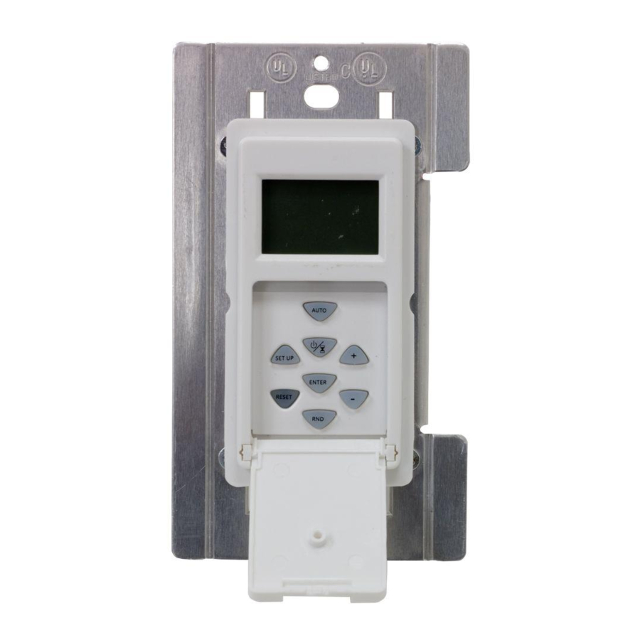
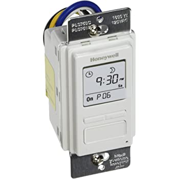
is that a normal timer or wifi type of 3 way switch ? They are different from normal 3 way switch hookups... you will have to google the manual for that unit.

something like this.


dogdog

Well-known member
Joined
Nov 15, 2011
Messages
12,711
I removed one of the two 3-way switches to upgrade it to a smart switch
which brand of smart switch are you upgrading to? if you don't care for the timer 3way... all you have to do is identify your wires and follow instruction from the smart switch manual.
 
To avoid these ads, REGISTER NOW!
OP
4

472scout

Well-known member
Joined
Sep 18, 2010
Messages
1,280
Location
back 40
which brand of smart switch are you upgrading to? if you don't care for the timer 3way... all you have to do is identify your wires and follow instruction from the smart switch manual.

It's a Kasa TP link. I was ID'ing the wires when I discovered one traveller always has 123v and the other traveller is either 0 or 60 depending on which way the toggle is flipped. When measured to ground anyway.
 

dogdog

Well-known member
Joined
Nov 15, 2011
Messages
12,711
I was ID'ing the wires when I discovered one traveller always has 123v and the other traveller is either 0 or 60 depending on which way the toggle is flipped. When measured to ground anyway.


The nature of that 3 way switch is a single pole double throw switch.

It dependents on how that switch is hooked up, if 120 line voltage is on the other end of the 3 way switch's Common terminal "the black or dull reddish color terminal (color is different from the other two) " Then one of the traveler wires will always have power. that is how 3 way switch works. Easier if you google up a 3 way switch diagram and see the load side (the side that goes to the lights ) and the line side (the side with incoming line power) hookup of it...

I am no electromagician, but I think you needed to verify against the neutral line not the ground line ( the bare copper wire), and if you are getting 60V some where, you might have some misconfigured electrical some where/ anywhere. I have that happened when I mis-configure one of the circuit to the bathroom and forgot the neutral, all those time, my bathroom stuff have been running ground as neutral... Till I scratch my head and fixed it.

anyways..

1) look up that wifi smart switch installation manual for 3 way, wifi switch and a like requires neutral and hot at the switch also.

2) identify your traveling wires and your 3 way switch configuration.

3) hopefully you have enough wires between the two boxes... don't have a good reference diagram for their switches via their websites so good luck, you might have issues dependents on what wires are at the other end of the 3way switch.


means map out which box the hot wires comes into, hopefully it is on the one you are installing the wifi switch.
 

cybrdyke

Well-known member
Joined
Sep 9, 2014
Messages
3,449
Location
USA
1 Caseta Master Switch and 2 Pico's. Done. Hell with all those wires.
CD
 

ycgoat

Well-known member
Joined
Mar 28, 2020
Messages
971
Location
S.E. Va
Safety first. I do not recommend a non electrician home owner work with energized wires.

I would be identifying which wires come from from each cable and where that cable goes to, since you are changing technologies how the old switches are wired is not that important except to identify where each wire goes and it looks like it may have been wired wrong at some point (the white tied to a black is a red flag and looks to be coming from the 3 conductor cable). Its hard to tell from the pictures, but it looks like 3 cables (2) 2 conductor cables and (1) 3 conductor; I would expect (1) 2 conductor from a power source, (1) 2 conductor to a light fixture, and the 3 conductor to the other switch box.

With power off; pull both 3 way switches out and verify where the cables running out of the boxes go. you can verify that the 3 conductor cable goes to the other switch by ringing them out using the continuity function of the meter and tying the conductors to ground 1 at a a time. Once you know which cables go between the switches and which cable is the power source, you can follow the instructions on the new switches.

To help verify which cable is the power source with the power off and devices removed. test for continuity between the white neutral and ground. Then you can verify testing voltage with the hot wire (wire nutted) and inserting the meter probe into the back of the wire nut.
 

justsam

Well-known member
Joined
Aug 20, 2010
Messages
1,268
Location
Penngrove, California
Can you provide the exact model number of switch? Do you want to maintain the 3 way capability? Many 3 way smart switches I have seen require a master slave relationship, two different switch types. Do not think of them as a regular SPDT 3 way switch.
 

yatg

Well-known member
Joined
Aug 16, 2019
Messages
2,830
Location
Southern Oregon

That switch has non-standard wiring. Only one traveler from the remote 3-way to the timer 3-way.


Regular 3-way switch logic and voltage readings will not apply.

You should identify the cables, line, travelers, load, and wire the new switch based on that.
 

Jim greengo

Well-known member
Joined
Sep 3, 2018
Messages
7,415
Location
Behind my house
I had the common on my meter clipped to the green (edit I meant to say copper) wire coming out of the wall.

The 5 wires are the white (neutral), copper (ground), black, brown, and red.
That's what was throwing me for a loop,the green wire.
That's why I asked about a picture.
 
OP
4

472scout

Well-known member
Joined
Sep 18, 2010
Messages
1,280
Location
back 40
So to close this out I ended up using a single pole smart switch since I don't need 2 switches for this light. Plus I would have had to steal power off the foyer light since I was 1 wire short. As some noticed my old set up only had 1 traveler and the new 3-way switch needed 2 travelers. Thanks again.
 
OP
4

472scout

Well-known member
Joined
Sep 18, 2010
Messages
1,280
Location
back 40
Does anyone want to take a shot at why I was getting 60v? I did check it to neutral and got 60v there as well.
 

ycgoat

Well-known member
Joined
Mar 28, 2020
Messages
971
Location
S.E. Va
A couple possibilities come to mind but without being sure what everything was in the system Its impossible to know.

1. Floating neutral
2. Voltage being reduced by another smart device or dimmer in the circuits
3. It was in series with another load
 
To avoid these ads, REGISTER NOW!
Top Bottom