To avoid these ads, REGISTER NOW!

Wiring Air Compressor

HaroRider

Well-known member
Joined
Oct 20, 2010
Messages
2,457
Location
New York
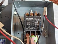
Hey all, I was wondering of anyone was familiar with wiring this air compressor. I took pictures of the wiring, its a Saylor Beall single phase 5 HP 220V compressor.

It has two black, a green, a red and a white coming from the motor side.
Going to the pressure switch is a white and black.

I really have no idea how this should be wired, and everything was disconnected before I purchased it.


Any and all info would be greatly helpful.

Thanks, Thomas
 

Attachments

  • Compressor 1.jpg
    Compressor 1.jpg
    122.8 KB · Views: 90
  • Compressor 2.jpg
    Compressor 2.jpg
    114.4 KB · Views: 84
  • Compressor 3.jpg
    Compressor 3.jpg
    108.8 KB · Views: 84
  • Compressor 4.jpg
    Compressor 4.jpg
    118 KB · Views: 82
  • Compressor 5.jpg
    Compressor 5.jpg
    123.8 KB · Views: 83
  • Compressor 6.jpg
    Compressor 6.jpg
    97.1 KB · Views: 84
Last edited:
To avoid these ads, REGISTER NOW!

Balvar24

Well-known member
Joined
May 18, 2016
Messages
870
Wiring diagram on the motor? Pressure switch should pull in the starter. One hot and neutral most likely required for that.
 
OP
H

HaroRider

Well-known member
Joined
Oct 20, 2010
Messages
2,457
Location
New York
Thanks Cobbler. I'll try to get a pic of the wiring diagram on the motor. (Not sure if there is one) Its a Dayton 6K854BA.
 

Attachments

  • 20220420_154821.jpg
    20220420_154821.jpg
    317 KB · Views: 83
Last edited:

The Cobbler

Super Moderator
Staff member
Joined
Oct 24, 2013
Messages
26,204
Location
Niagara Region, Ontario, Canada
not sure why you have so many wires comming out of the motor. I wonder if they had a capacitor in the contactor box instead of in the motor? with the tabs on those wires it has me wondering ...
 

wyliesdiesels

Well-known member
Joined
Aug 14, 2012
Messages
20,244
Location
Modesto, CA
Hey all, I was wondering of anyone was familiar with wiring this air compressor. I took pictures of the wiring, its a Saylor Beall single phase 5 HP 220V compressor.

It has two black, a green, a red and a white coming from the motor side.
Going to the pressure switch is a white and black.

I really have no idea how this should be wired, and everything was disconnected before I purchased it.


Any and all info would be greatly helpful.

Thanks, Thomas
Can you open the motor junction box and take a picture?

theres too many wires coming from the motor

you also need to check the overload heater to make sure its sized correctly
 

pattenp

Well-known member
Joined
Jun 4, 2008
Messages
10,175
Location
Virginia - USA
Something seems off. I see small flex that goes to pressure switch then another small flex going behind box which looks like it's heading to the motor. So exacty where does the large flex (off picture) come from? I know the OP said coming from motor side but wanted to make sure.
 
OP
H

HaroRider

Well-known member
Joined
Oct 20, 2010
Messages
2,457
Location
New York
Hmmm, I hope I didn't make a mistake. Let me check today to be 100% sure all those wires come from the actual motor. Thanks for the help thus far.
 

Norcal

Well-known member
Joined
Mar 16, 2008
Messages
13,792
DP/definite purpose, contactors sometimes dont have field swappable components...
DP contactors are a throwaway item, no replacement parts, limited accessories, some say the "DP" stands for don't purchase, they are used where cheap is the way, & just has to last past the warranty expiration.
 
OP
H

HaroRider

Well-known member
Joined
Oct 20, 2010
Messages
2,457
Location
New York
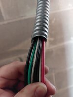
Ok guys, Im sorry that goes to the whip (Power side in) Not the motor
 

Attachments

  • 20220727_121221.jpg
    20220727_121221.jpg
    213.7 KB · Views: 59
  • 20220727_120934.jpg
    20220727_120934.jpg
    261.4 KB · Views: 49
  • 20220727_120806.jpg
    20220727_120806.jpg
    311.2 KB · Views: 44
  • 20220727_120743.jpg
    20220727_120743.jpg
    212.8 KB · Views: 39
OP
H

HaroRider

Well-known member
Joined
Oct 20, 2010
Messages
2,457
Location
New York
Pictures
 

Attachments

  • 20220727_120740.jpg
    20220727_120740.jpg
    217.6 KB · Views: 34
  • 20220727_120906.jpg
    20220727_120906.jpg
    167.4 KB · Views: 36
  • 20220727_121024.jpg
    20220727_121024.jpg
    193.2 KB · Views: 40
OP
H

HaroRider

Well-known member
Joined
Oct 20, 2010
Messages
2,457
Location
New York
Schematics
 

Attachments

  • 20220727_122212.jpg
    20220727_122212.jpg
    254.9 KB · Views: 41
  • 20220727_122223.jpg
    20220727_122223.jpg
    261.2 KB · Views: 37
  • 20220727_122405.jpg
    20220727_122405.jpg
    284.2 KB · Views: 45
To avoid these ads, REGISTER NOW!
OP
H

HaroRider

Well-known member
Joined
Oct 20, 2010
Messages
2,457
Location
New York
Yes, I know this compressor was in series with another compresor at one point. Im so lost on how to connect it. Or even if the existing connections are correct.
 

whateg01

Well-known member
Joined
Mar 13, 2006
Messages
11,965
Location
doo dah, kansas, usa
Yes, I know this compressor was in series with another compresor at one point. Im so lost on how to connect it. Or even if the existing connections are correct.
How it was collected before is irrelevant aside from finding the correct wires to connect now. I would just rip out all the existing wires and wire it correctly.
 
OP
H

HaroRider

Well-known member
Joined
Oct 20, 2010
Messages
2,457
Location
New York
Gotcha, so I technically only need a red, a black, and a green? The rest can be pulled through and removed?
 

wyliesdiesels

Well-known member
Joined
Aug 14, 2012
Messages
20,244
Location
Modesto, CA
Gotcha, so I technically only need a red, a black, and a green? The rest can be pulled through and removed?
That depends on how you end up wiring your control circuit. The contactor you have uses a 120 V coil so you will either need to replace that with a 240 V controlled contactor or you’ll need a neutral ran into the contactor box from your power whip

But other than that you only need 2 ungrounded conductors and ground
 
OP
H

HaroRider

Well-known member
Joined
Oct 20, 2010
Messages
2,457
Location
New York
I would add a switch somewhere, probably on the coil line so I could manually shut it off when I didn't want to run.itsny you mention this. I really want a light switch near the rest of my light switches.

I would add a switch somewhere, probably on the coil line so I could manually shut it off when I didn't want to run.
Its funny that you mention this. I really want to have a light switch to turn off the compressor. The reason for this would be because I know I will forget to turn the compressor off. However if the switch is near the light switch I won't forget to turn it off.
 
Last edited:

whateg01

Well-known member
Joined
Mar 13, 2006
Messages
11,965
Location
doo dah, kansas, usa
I started to put together a magnetic switch for my compressor that has a timer built in. That way, I hit the button and it's active for, say, an hour, then after that it won't kick on until I press the button again. I would add an override so if I was going to be painting all day, I wouldn't have to keep resetting it.
 
OP
H

HaroRider

Well-known member
Joined
Oct 20, 2010
Messages
2,457
Location
New York
I definitely want the switch. I dont want the unit to turn on overnight. Perhaps from a cold outside temperature pressure drop or small air leak.

Bump, for help with wiring.
 
Last edited:

whateg01

Well-known member
Joined
Mar 13, 2006
Messages
11,965
Location
doo dah, kansas, usa
are you going to reuse the existing contactor? If not, I believe it will make wiring easier. I'm not sure what wire colors are going where. I tried to follow them in the pics, but it was confusing, so I would suggest starting fresh there. There are parts of the starter that I can't see, so it's hard to tell how it is wired or should be wired, relative to the diagram.
 
OP
H

HaroRider

Well-known member
Joined
Oct 20, 2010
Messages
2,457
Location
New York
I plan on using the existing contactor. Isnt this contactor needed for this size of a motor?

- I have a white and black going to the pressure switch. These connect to the whip with all the wires (Power Side)

- I have two blacks going to the motor itself. These connect to the contactor itself (Previously connected) I attached a pic of where these go to this post.

- I then have, three blacks, two whites a red and a green at the whip. (These are where the pressurecswitch is going)

I hope that makes sense.

Thanks for the help!
 

Attachments

  • 20220727_120934.jpg
    20220727_120934.jpg
    261.4 KB · Views: 31

wyliesdiesels

Well-known member
Joined
Aug 14, 2012
Messages
20,244
Location
Modesto, CA
you can use that contactor but the problem is you will need to pull a neutral from your electrical panel because the coil is 120v not 240v. or you would need a control transformer...

having a 120v rated coil just complicates things...
 

Sumboodie

Well-known member
Joined
Mar 20, 2021
Messages
11,039
Location
AK
You never have leaks until you do. And then you have a leak.
My compressor wasn't turned off aside from a few times I was out of town for a few weeks and happened to thing of it. 12 years without any problem.
 
OP
H

HaroRider

Well-known member
Joined
Oct 20, 2010
Messages
2,457
Location
New York
you can use that contactor but the problem is you will need to pull a neutral from your electrical panel because the coil is 120v not 240v. or you would need a control transformer...

having a 120v rated coil just complicates things...
Pulling a neutral to the unit will not be an issue. Its just a matter of wiring it.
 
To avoid these ads, REGISTER NOW!
Top Bottom