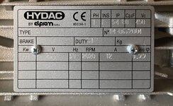
The nameplate on your motor says 1 PH, you need a three phase motor. It also says 110-120 volt. I have no clue where you would buy a controller for it, other hen the factory.Just curious to find out why VFD would not work on my existing motor.Isn't the burned control board on it basically a VSD ?


You are using an out of date browser. It may not display this or other websites correctly.
You should upgrade or use an alternative browser.
You should upgrade or use an alternative browser.
Coats GTS 70 tire machine motor
- Thread starter waybel
- Start date

It is about 1/2 the RPM of the original, and is it reversible?
One like this and a VFD,
https://www.ebay.com/itm/1254786756...1s6T5aUXLrYG/G9sW4h6RGNyy6|tkp:Bk9SR5aZirCAYQ
It also depends on how much room you have for a replacement motor.
One like this and a VFD,
https://www.ebay.com/itm/1254786756...1s6T5aUXLrYG/G9sW4h6RGNyy6|tkp:Bk9SR5aZirCAYQ
It also depends on how much room you have for a replacement motor.
Just trying to get this going for a little as possible .The motor shown is $200 US i live in Canada so costs me a lot more .If it has a control that does what i want would be a lot cheaper than the motor and VFD.That motor alone is a good price but they want $125 US for shipping.That VFD reccomended is $285 US plus shipping .That is $760 Canadian dollars
I was wondering if i could just get a 120 volt 1 HP reversible motor and one of these reverse switches and make it work on the foot pedal?Does your motor now work on high or low speed? Just wondering what RPM would be suitable at 1 speed.The description on the data plate sounds like it is a motor/inverter combination. I have a Hunter tire machine with a similar setup. Mine now only has 1 speed instead of 2. I need to dig into it, as well. You can buy a relatively inexpensive vfd on Amazon that might work if the motor is OK.
Attachments

petebob
Well-known member
Physically, i would think that would work but you would have to verify the torque is enough to actually mount a tire. That will depend on the gearbox between the motor and the table and the pulley sizes, assuming it is belt driven.
I believe my motor is OK so I'm going to use an aftermarket vfd to run it. Mine currently only has one speed somewhere between what the high and low speeds should be.
I believe my motor is OK so I'm going to use an aftermarket vfd to run it. Mine currently only has one speed somewhere between what the high and low speeds should be.
Please keep me informed.I may go that route also.Was reading and a lot of people say when buying a cheap VFD to get one that is double the hp and amps of the motor you are using.Saw a pile of reviews on Amazon saying similarPhysically, i would think that would work but you would have to verify the torque is enough to actually mount a tire. That will depend on the gearbox between the motor and the table and the pulley sizes, assuming it is belt driven.
I believe my motor is OK so I'm going to use an aftermarket vfd to run it. Mine currently only has one speed somewhere between what the high and low speeds should be.
Any updates on the VFD you tried?Please keep me informed.I may go that route also.Was reading and a lot of people say when buying a cheap VFD to get one that is double the hp and amps of the motor you are using.Saw a pile of reviews on Amazon saying similar
petebob
Well-known member
Hi! I've finally taken the time to install the vfd and get it working. I bought this one from AmazonAny updates on the VFD you tried?
It uses a 220v 1Ph supply and outputs 3Ph to run the motor. My motor runs @ 1750 rpm @ 60Hz. I set the high speed @ 120 Hz and the low speed @ 80Hz to closely match the original rpm of the table. I haven't used it yet, but it works fine with no load.
Good.I got my hands on a 220 volt 3 phase motor and bought aHi! I've finally taken the time to install the vfd and get it working. I bought this one from Amazon
It uses a 220v 1Ph supply and outputs 3Ph to run the motor. My motor runs @ 1750 rpm @ 60Hz. I set the high speed @ 120 Hz and the low speed @ 80Hz to closely match the original rpm of the table. I haven't used it yet, but it works fine with no load.
HUANYANG GT-Series (220V, 2.2KW)
https://www.amazon.ca/dp/B077KS9LRY/?tag=atomicindus04-20 vfd .Ran a 220 volt feed and thats about as far as i have gotten .Think wiring it to motor will not be an issue .Trying to wire the 3 switches for low / high and reverse that operate off the pedal may be another story.Attachments

Last edited:
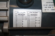
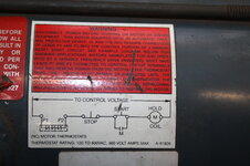
That should not be an issue. I looked at the wiring diagram and the green wire is common and the red, black and brown wires are rotation and high low speed.Good.I got my hands on a 220 volt 3 phase motor and bought a
HUANYANG GT-Series (220V, 2.2KW)
https://www.amazon.ca/dp/B077KS9LRY/?tag=atomicindus04-20 vfd .Ran a 220 volt feed and thats about as far as i have gotten .Think wiring it to motor will not be an issue .Trying to wire the 3 switches for low / high and reverse that operate off the pedal may be another story.
It should be fairly simple.
Well i am getting at it.Trying to go slow as to not mess anything up.Ran the 220 wire to it;s location .Any idea where the green,red,black and brown wires go on the VFD?Also where do theThat should not be an issue. I looked at the wiring diagram and the green wire is common and the red, black and brown wires are rotation and high low speed.
It should be fairly simple.
P1 and P2 wires go as stated on the label on the engine?Thanks for now
Attachments

Last edited:
No! Did you get a manual?Well i am getting at it.Trying to go slow as to not mess anything up.Ran the 220 wire to it;s location .Any idea where the green,red,black and brown wires go on the VFD?
The "fun" part about VFD's is figuring out the control wiring and programing. It can be a bit of brain work. I will often will program the VFD to what I think should work, hook up jumper wires and touch them together to verify the control function.
Here is a link to the manual,
https://www.automationtechnologiesinc.com/wp-content/uploads/downloads/2018/08/GT-series-manual.pdf
Have manual but doesn't really say anything about where to hook up wires.Will keep reading and maybe ask for support on Huanyang site .I don't think i am at the stage to start to start jumping wires.Will probably fry a new 220 VFD lol
Look at diagragm 4-13. COM and S1 through S7 are the controll terminals. I am looking, but you will need to program these terminals to do what you want.Have manual but doesn't really say anything about where to hook up wires.Will keep reading and maybe ask for support on Huanyang site .I don't think i am at the stage to start to start jumping wires.Will probably fry a new 220 VFD lol
P5 Group Input Terminals starting on page 44 are for programing these terminals.
Make sure before you do anything in regards to trying to run the motor you have all the motor parameters programed.
5.2.3 Motor parameters autotuning - page 25
Thank you for all the info.Will look into all of this and let you know what i find outLook at diagragm 4-13. COM and S1 through S7 are the controll terminals. I am looking, but you will need to program these terminals to do what you want.
P5 Group Input Terminals starting on page 44 are for programing these terminals.
Make sure before you do anything in regards to trying to run the motor you have all the motor parameters programed.
5.2.3 Motor parameters autotuning - page 25
Just curious but should i have some kind of on/off switch in between power source and VFD and if so what would could i use ?After programming VFD and then shutting power off to it does it keep the settings in memory somehow? Should the main power source ground be hooked to the ground shown at the end of the VFD # 9 ?I see lots of videos showing ground to chassis .
Attachments

petebob
Well-known member
Congratulations! You're almost there. I wired the low speed switch to the low input (SPL) and high to the high speed input (SPH) and ran a jumper from the low speed switch to the forward (FOR) rotation input because mine needed a speed signal and direction. It look like with PD047 and PD048, you can set what happens with each switch on yours.
Thanks .When i do get there what rpm should i set for low and high speed .I have no idea what the old motor was.Did you hook some type of switch in between the main power and the VFD?Congratulations! You're almost there. I wired the low speed switch to the low input (SPL) and high to the high speed input (SPH) and ran a jumper from the low speed switch to the forward (FOR) rotation input because mine needed a speed signal and direction. It look like with PD047 and PD048, you can set what happens with each switch on yours.
When you say manually, do you mean from the key pad? There should be a setting in the parameters to control from remote or something similar.Well bench tested it and got it running fprward and reverse maually.Now on to fun part trying to get the 2 speeds and reverse working for the foot pedal
I was wondering about the two speed thing. I am not sure how the existing switches function on the changer. At least you cave forward and reverse. If you are not able to do the two speed deal it is still usable.
No idea what RPM to run it at. You can set it in the parameters later on. I would not worry about it. Maybe set the low at 30 Hz and the high at 60 Hz and see what you get on the tire machine when you get the motor mounted, expect to change the settings later.Thanks .When i do get there what rpm should i set for low and high speed .I have no idea what the old motor was.Did you hook some type of switch in between the main power and the VFD?
I would put a switch of some sort to power it down when it is not being used. It doesn't hurt them to leave the VFD running. but on a tire machine I assume it might be months in between uses.
Do not put any kind of disconnect between the VFD and motor!
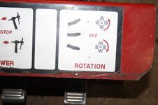
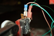
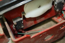
foot pedal lifted activates the reverse micro switch (red and green wire)When you say manually, do you mean from the key pad? There should be a setting in the parameters to control from remote or something similar.
I was wondering about the two speed thing. I am not sure how the existing switches function on the changer. At least you cave forward and reverse. If you are not able to do the two speed deal it is still usable.
foot pedal pressed half way activates low speed bottom micro switch (black and green wires)
foot pedal depressed all the way down activates high speed upper micro switch (brown and 3 green wires)
Attachments


petebob
Well-known member
I got the speeds of my table from Hunter's brochure I found online. Reverse and high are 15 rpm and low speed is 7 rpm. I bought a little photo tach that worked on the motor. On the actual table, I just marked it and timed one revolution and then played with the frequency to get those speeds.
Well i got the vfd attached to the tire machine and the motor installed .It operates properly from the keypad . I ran the wires from the switches to the vfd. Now i need some help.I ran the black wire from low speed switch to S1 the brown wire high speed to S2 and the red wire Reverse to S3 ran the green wire to ground. I must have forgotten something in programming or done something wrong because when i depress pedal for switches i get nothing.Could someone give me a quick run through or have a clue what i have done wrong
petebob
Well-known member
One of the options I had to set was whether the control input comes from the panel or external switches. Yours is probably the same.Well i got the vfd attached to the tire machine and the motor installed .It operates properly from the keypad . I ran the wires from the switches to the vfd. Now i need some help.I ran the black wire from low speed switch to S1 the brown wire high speed to S2 and the red wire Reverse to S3 ran the green wire to ground. I must have forgotten something in programming or done something wrong because when i depress pedal for switches i get nothing.Could someone give me a quick run through or have a clue what i have done wrong
petebob
Well-known member
One of the options I had to set was whether the control input comes from the panel or external switches. Yours is probably the sam
petebob
Well-known member
I just looked at the manual for yours. PD001 should be set to 1 for external commands.
petebob
Well-known member
I think PD023 should be set to 1 to allow reverse rotation. Default is 0.
Page 96, parameter P0.01 Run command source, set to 1 terminal.
I have to tell you, this is the worst VFD manual I have ever had the pleasure to wade through!
That Appendix B starting on page 95 is usually he first thing listed in the programing section of manuals I have used!
I never got this far through this manual until a few minutes ago!
I have to tell you, this is the worst VFD manual I have ever had the pleasure to wade through!
That Appendix B starting on page 95 is usually he first thing listed in the programing section of manuals I have used!
I never got this far through this manual until a few minutes ago!
petebob
Well-known member
Sorry, I had the wrong manual.
Very confusing especially for a newbie like me trying to figure out my first VFD. I sent a message to Huanyang Electric asking them for assistance as i can't figure out this manual .Here is what they said.I told them i hooked up the 3 wires for low,high and reverse to S1 S2 S3 and the green wire to groundPage 96, parameter P0.01 Run command source, set to 1 terminal.
I have to tell you, this is the worst VFD manual I have ever had the pleasure to wade through!
That Appendix B starting on page 95 is usually he first thing listed in the programing section of manuals I have used!
I never got this far through this manual until a few minutes ago!
He said Based on your information, it seems that you need to start the motor with an external potentiometer control You need to connect the S1 and COM terminals,then set P0.01=1,This parameter is the starting parameter of the external switchThen you can start it with an external switch. Thank you
i said So the wiring i have done is not correct? Or is the wiring correct and i have to jumper the S1 and com also ?
he answered
The wiring should be correct, but some parameters need to be reset. P0.01=1 (external potentiometer parameter, need to be set first) p5.01=16 (Corresponds to the frequency of S1 low speed switch) p5.02=17 (Corresponds to the frequency of S2 high speed switch) p5.03=2 (reversal) After setting, the speed can be adjusted through the knob pA.04= 0-100 (This is the percentage of your current rotation speed. For example, if you have a 50hz motor =1740RPM, then if this parameter is set to 50, the speed will become 870RPM) .low speed switch corresponding to S1 connection PA.06= 0-100 (Same thing as up here, but it corresponds to the velocity of S2 high speed switch )
Still not sure if i have wiring correct .I sent him another question asking this waiting for an answer
You are not using an external potentiometer so no clue why they say to use that parameter!
You know, I would skip the multi speed for now and just see if you can get it to run! Set P5.01 to 1 Forward and see what happens when you hit the switch.
Sometimes when I have had to program a new to me VFD I tried set it up as simple as I could and got it running, then slowly started changing parameters and inputs to see what would happen.