

You are using an out of date browser. It may not display this or other websites correctly.
You should upgrade or use an alternative browser.
You should upgrade or use an alternative browser.
Coats GTS 70 tire machine motor
- Thread starter waybel
- Start date
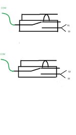
i ended up using these setting
S1, S3, wired together is for low speed
S2, S3 wired together is for high speed
S4 is for reverse
And green wire from switches to COM
Used the PLC to program the 2 speeds
S3 is the Main FWD Run Terminal Connection S4 is the Reverse Connection
P0.01=1 (Remote Control)
P5.01=16 (S1 Terminal=Multi-Step Speed 1)
P5.02=17 (S2 Terminal=Multi-Step Speed 2)
P5.03=1 (Forward RUN) S3Terminal connection
P5.04=2 (Reverse RUN) S4Terminal connection
PA.04=20% (Adjustable 0-100% RPM Speed 1) This is a PLC Parameter to set the Slow Speed.
PA.06=30% (adjustable 0-100% RPM Speed 2) This is a PLC Parameter to set the Fast / Rapid Speed
Last edited:
Well after i thought i had this solved completely i didn't . I only had low speed and reverse connected when i tried it.When i hooked the high speed connection on neither would work.If i disconnected high speed the low speed and reverse would work and the same if i disconnected low speed the high speed and reverse would work Huanyang who was also helping and showed me wiring and parameters now saysI got the speeds of my table from Hunter's brochure I found online. Reverse and high are 15 rpm and low speed is 7 rpm. I bought a little photo tach that worked on the motor. On the actual table, I just marked it and timed one revolution and then played with the frequency to get those speeds.
|
No even went the pedal is in the off position in the middle where it is not contacting any switches nothing happens when the 2 switches are wired .Think i can live with just one speed and reverse anyways.Tried the tire machine today and it works fine
petebob
Well-known member
It seems odd that just having the other switch wired would cause it not to work. Are they in series so one is blocking the circuit from being closed?
I used a jumper from the low speed terminal to the run terminal because the drive wanted a run signal as well as which speed. My low speed switch stays closed in high speed, too so it could provide that signal.
I used a jumper from the low speed terminal to the run terminal because the drive wanted a run signal as well as which speed. My low speed switch stays closed in high speed, too so it could provide that signal.
When i wire the 2 speeds the pedal is in off position so that none of the 3 switches are on .When i press the pedal for the first low speed switch nothing happens or press the pedal all the way down to activate the high speed switch nothing happens .If i disconnect one of them the other and reverse work
petebob
Well-known member
I think your high speed switch is getting a signal from S3 when theblow speed awitch is made and vice versa. So it sees s1 and s2 high at the same time. If you remove the connection to s3 from one speed, does the other work? If so, you could use 2 diodes to get the signal from S1 to S3 for low and one from S2 to S3 for high speed.
I missed this earlier. I agree, basically jumpering S1, S2 and S3 together isn't going to work. The OP needs to fine double pole micro switches, or find some other way to isolate the control wiring.I think your high speed switch is getting a signal from S3 when theblow speed awitch is made and vice versa. So it sees s1 and s2 high at the same time. If you remove the connection to s3 from one speed, does the other work? If so, you could use 2 diodes to get the signal from S1 to S3 for low and one from S2 to S3 for high speed.
A couple diodes might work.
Nothing special as there is not real power on the control side. What ever you can find should work.i may try the diode trick .Any certain size of diode you guys would recommend?
Bit confused .Where would i put the 2 diodesI think your high speed switch is getting a signal from S3 when theblow speed awitch is made and vice versa. So it sees s1 and s2 high at the same time. If you remove the connection to s3 from one speed, does the other work? If so, you could use 2 diodes to get the signal from S1 to S3 for low and one from S2 to S3 for high speed.
You need the wire from the switch going to S1 and the other switch to S2, then jumper from S1 to S3 with a diode and from S2 to S3 with a second diode. If they don't work, try switching the diode leads. I am not sure what the polarity is on the VFD controls.
The manual says 24 volt, but is it AC or DC voltage? I assume DC, but I would not swear to it.
If you have a volt meter test voltage from COM to S1 and see what it reads, AC or DC voltage.
If AC the diode deal will not work.
The manual says 24 volt, but is it AC or DC voltage? I assume DC, but I would not swear to it.
If you have a volt meter test voltage from COM to S1 and see what it reads, AC or DC voltage.
If AC the diode deal will not work.
Last edited:
Will the one speed work work wit the other wire disconnected? If you wire S1, S3 and com do you get one speed, then wire S2, S3 and com do you get the other speed?
I said earlier I often just use jumper wires to sort thinks out. The voltage coming from the control terminals will not even tickle you, so no worries about just trying wires and no switches.
I said earlier I often just use jumper wires to sort thinks out. The voltage coming from the control terminals will not even tickle you, so no worries about just trying wires and no switches.
Well, then you know the control wiring is screwing it up.yes both speeds work if you disconnect the other
IMO, you need to go with something like this,
https://www.amazon.com/dp/B005T7E1JA/?tag=atomicindus08-20
This switch would allow you to isolate the COM, S1, S3 and the COM, S2, S3 dilemma. Wired like this there will ber no cross connection.
Attachments

Yes, you might find them elsewhere for a better price. I just looked on Amazon.So i need 2 of those switches and these replace the 2 that are on the foot pedal for high and low that are there now?
Just jumper the S3 from switch to switch.They don't look too expensive like 5 for $12 i guess i would have to run another wire from S3 back to the switch
I just realized I messed up the switch drawing, so this one instead
Attachments

Doesn't look like any of those switches would work they are all SPDTWell, then you know the control wiring is screwing it up.
IMO, you need to go with something like this,
https://www.amazon.com/dp/B005T7E1JA/?tag=atomicindus08-20
This switch would allow you to isolate the COM, S1, S3 and the COM, S2, S3 dilemma. Wired like this there will ber no cross connection.
petebob
Well-known member
I would check for continuity from s1 to com and s3 to com @ low speed and s2 to com and s3 to com when the high switch is made. Also, make sure there is no continuity between s1 and s2 @ any switch position. When the pedal is released, there shouldn't be any continuity from S3 to any other lead.
The link shows a DPDT switch. The factory switch on the Coats tire changer is SPDT.Doesn't look like any of those switches would work they are all SPDT
It's all good .I have checked this several timesI would check for continuity from s1 to com and s3 to com @ low speed and s2 to com and s3 to com when the high switch is made. Also, make sure there is no continuity between s1 and s2 @ any switch position. When the pedal is released, there shouldn't be any continuity from S3 to any other lead.
petebob
Well-known member
Then it seems it has to be something in the settings. I'll look through your manual and see how similar the parameters are to mine.
Then it seems it has to be something in the settings. I'll look through your manual and see how similar the parameters are to mine.
petebob
Well-known member
Looking at the chart on p. 69, I would try to use stage 5 (S1,S3 high) and 6 (S2,S3 high) for your 2 speeds instead of stage 1 and 2.
These are currently the only parameters i currently have .Which parameters should i be putting in to match what you said to try?Looking at the chart on p. 69, I would try to use stage 5 (S1,S3 high) and 6 (S2,S3 high) for your 2 speeds instead of stage 1 and 2.
P0.01=1 (Remote Control)
P5.01=16 (S1 Terminal=Multi-Step Speed 1)
P5.02=17 (S2 Terminal=Multi-Step Speed 2)
P5.03=1 (Forward RUN) S3Terminal connection
P5.04=2 (Reverse RUN) S4Terminal connection
PA.04=20% (Adjustable 0-100% RPM Speed 1) This is a PLC Parameter to set the Slow Speed.
PA.06=30% (adjustable 0-100% RPM Speed 2) This is a PLC Parameter to set the Fast / Rapid Speed
Last edited: Jan 15, 2023
I will admit, I a confused.Looking at the chart on p. 69, I would try to use stage 5 (S1,S3 high) and 6 (S2,S3 high) for your 2 speeds instead of stage 1 and 2.
Waybel says each speed works when independently wired, so it looks like the jumpering of S3 to the other inputs throug the single pole switch is the cause. How does this clear that up?
petebob
Well-known member
PA.04 is multi speed step 1 and PA.06 is step 2. When switch s1 and s3 are made, the chart indicates to use stage 5. I interpret that as step 5. So, I would switch PA.04 for PA.12. I would switch PA0.6 for PA.14. I'm just guessing and I've never played with a vfd before the one I put on my machine. The defaults on those are 0, so it would make sense that it wouldn't run. Does the display show the commanded frequency?
petebob
Well-known member

Sure, but you still need to close S1, S3 and S2, S3. The problem is with the wiring from the control switches. Perhaps I am missing somthingPA.04 is multi speed step 1 and PA.06 is step 2. When switch s1 and s3 are made, the chart indicates to use stage 5. I interpret that as step 5. So, I would switch PA.04 for PA.12. I would switch PA0.6 for PA.14. I'm just guessing and I've never played with a vfd before the one I put on my machine. The defaults on those are 0, so it would make sense that it wouldn't run. Does the display show the commanded frequency?
Is there a parameter that will get you foreward control and one spped and forward control and second speed with using one input each? or without sharing S3?
My understanding is this is what he has now and the problem arises with pretty much jumpering S1,S2,S3 together wit the switches. We need to move away from the sharing of S3 or isolate the control signals.
Attachments
Correct but how do you energize S1 S3, and then S2, S3 with single pole switches and keep S1 and S2 isolated???I'm just guessing.... but it has 2 made switches so it looks at step 5 for the required frequency. The default frequency is 0, so it shouldn't run.
How does this clear that up?
I don't see where that cures the wiring problem.
Also having a difficult time finding those 2 DPDT switches to match what i have so that the existing pedal lobes will work on the new switches. The only ones i have found are like $60 for 2 plus shipping and i am not spending that much
petebob
Well-known member
He used diodes. Checking continuity for each switch position it sounds correct to me.Correct but how do you energize S1 S3, and then S2, S3 with single pole switches and keep S1 and S2 isolated???
I don't see where that cures the wiring problem.