Inline splice will be harder to tuck in the box than if both wires entered from the same side.
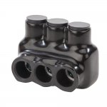
Most of the time I would go with the insulated splice vs taping it. Main reason for that is my time to tape it is more expensive than the insulated splice. If I was doing it for myself I would use the splice reducer or a split bolt and tape it with rubber then electrical tape.
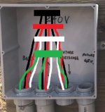
Have to ask why you're running 1/0 ground. Normally #6 would suffice but since your phase wires are upsized the ground does need to be at least a #3. Still quite a bit smaller than 1/0.
Most of the time I would go with the insulated splice vs taping it. Main reason for that is my time to tape it is more expensive than the insulated splice. If I was doing it for myself I would use the splice reducer or a split bolt and tape it with rubber then electrical tape.
Have to ask why you're running 1/0 ground. Normally #6 would suffice but since your phase wires are upsized the ground does need to be at least a #3. Still quite a bit smaller than 1/0.
") ) and a neater installation.
) and a neater installation.