To avoid these ads, REGISTER NOW!

Voltage Drop and Wire Size - Detached Barn Project

larry4406

Well-known member
Joined
Jan 27, 2006
Messages
19,248
Location
Northern Virginia
I need some guidance on sizing of wiring to a detached barn. This includes the 4-wire feed to the barn, and exterior outlets and lighting circuits fed back from the barn. Sorry for long post.

The detached barn will be fed from the house 200A panel. The barn has a 100A main breaker panel, separate neutral and ground bars, and a UFER ground.

Power Distribution
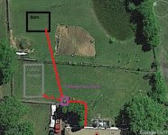
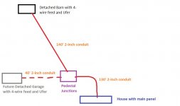
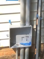
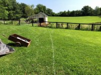
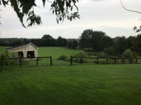
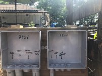
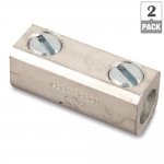
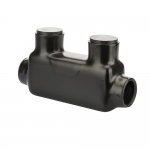
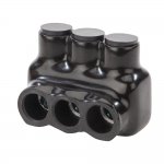
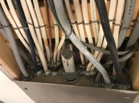
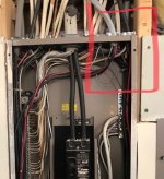
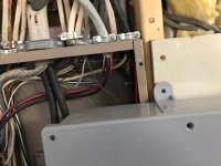
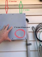
See the attached schematic and aerial view. The total conductor path for the 240V feed will be about 270'. I have 2" conduit for all but the 30' at the house. I have a junction box at the house where I will transition from SER to the underground wire using a Polaris type connector. There is an intermediate pedestal junction to aid in pulling as well as allow a feeder tap for a future detached. Since its piped in conduit from the house junction box to the barn panel, I plan on using XHHW instead of MHF.

Using the linked voltage drop calculator, it says that 2/0 at 240V, 270' and 100A would have a voltage drop of 3% which I understand is acceptable. Therefore, would you agree that 2/0-2/0-2/0-1 is suitable? This would be the size of the SER and the XHHW.
http://www.csgnetwork.com/voltagedropcalc.html

Exterior Outlets
See the attached schematic and aerial view. There will be 3 outlets fed from the barn. Plug 1 (P1) is at the barn, Plug 2 (P2) will be on an intermediate fence post 75' away, while Plug 3 (P3) will be at the pedestal junction a total of 140' away. Using the same linked voltage drop calculator for 120V, 140' and 20A, it says that #6 is needed to stay under 3% drop. If using THWN, I assume that both the neutral and hot are #6, but what for the ground?. How is #6 connected to the outlet itself, use of short 12g jumpers and wire nuts?

Exterior Lighting
See the attached schematic and aerial view. There will initially be 3 lights on a 3-way circuit. Light 1 (L1) is at the barn, Light 2 (L2) will be on an intermediate fence post 75' away, while Light 3 (L3) will be at the pedestal junction a total of 140' away. There will be one switch at the barn and the other switch at the house. The total conduit distance between switches is 260' which I assume is the length to use for sizing. Using the same linked voltage drop calculator for 120V, 260', and 15A, it says that #6 would be at 3.1% drop. I plan on using LED lighting at all 3 lamps (for comparison, 3 100W incandescent bulbs would pull about 2.5A). What THWN wire would you pull for this lighting circuit? With such a low predicted amperage I am thinking 12g is more than suitable.

Lastly, since the lighting and outlet wiring is all in the same shared 1" conduit, would you share the neutrals and handle tie the two breakers? Or just pull separate neutrals?

Thanks for your help. All conduits are in place so the pathways are fixed.
 

Attachments

  • Aerial View.jpg
    Aerial View.jpg
    89 KB · Views: 85
  • Power Distribution Schematic.jpg
    Power Distribution Schematic.jpg
    52.3 KB · Views: 85
  • Lighting and Exterior Outlet Schematic.jpg
    Lighting and Exterior Outlet Schematic.jpg
    66.2 KB · Views: 86
  • Junction Boxes.jpg
    Junction Boxes.jpg
    70 KB · Views: 94
  • Pedestal Junctions Backfilled.jpg
    Pedestal Junctions Backfilled.jpg
    152.5 KB · Views: 73
  • House Junction Box Zoom.JPG
    House Junction Box Zoom.JPG
    91 KB · Views: 86
  • Barn Trench Before.jpg
    Barn Trench Before.jpg
    152.2 KB · Views: 71
Last edited:
To avoid these ads, REGISTER NOW!
OP
L

larry4406

Well-known member
Joined
Jan 27, 2006
Messages
19,248
Location
Northern Virginia
Wow silent crowd.

Voltage drop calculators are all over the map for the barn feeder. Inputs 240V 100A 270 ft aluminum. How can answers be so diverse?

Science is pretty specific.

Apparently garbage in garbage out?
2/0 conductors 2.76% https://www.calculator.net/voltage-drop-calculator.html?
2/0 conductors 1.5%
http://www.prioritywire.com/calculator_voltage_drop.php
2/0 conductors 2.87% https://www.omnicalculator.com/physics/voltage-drop
3/0 conductors 2.8% http://www.electrician2.com/calculators/vd_calculator_initial.html
3/0 conductors VD not specified https://www.encorewire.com/wp-content/uploads/Voltage_Drop.html
4/0 conductors 2.5% http://www.nooutage.com/vdrop.htm
material=aluminum&wiresize=0.2557&voltage=240&phase=ac&noofconductor=1&distance=270&distanceunit=feet&amperes=100&x=59&y=23[/url]
4/0 conductors 2.63% https://www.southwire.com/calculator-vdrop

Regarding the outlet and lighting circuits I am thinking I will size them based on 80% of the 20A for the outlets (ie 16A) and the lighting based on the actual anticipated load (2.5 A). Need a calculator that is worth a damn.

Who has a feeder calculator or chart that is worth a damn? Variance from 2/0 to 4/0 is insane.
 

wyliesdiesels

Well-known member
Joined
Aug 14, 2012
Messages
20,012
Location
Modesto, CA
I peruse this forum multiple times per day and weirdly this is the first time your thread has popped up.

Ive noticed this before and think there is a glitch...

As to the VD calcs, ill have to check them when i get home.
 
OP
L

larry4406

Well-known member
Joined
Jan 27, 2006
Messages
19,248
Location
Northern Virginia
It all depends on the amperage requirement for the future feeder tap

The future detached garage would have a 100A main breaker panel and the same feeder tap size as the barn. The barn is further from the house breaker at 270' compared to 170' for the detached.

The plan for the future detached garage is to use a Polaris "T" style connector and splice the barn feeder to enable a same size feeder to the future detached. This avoids refeeding the barn from the future detached garage as a sub panel which was my original plan (which would make the pathway to the barn even longer). The concept of the feeder tap was brought up in my other hand hole thread. https://www.garagejournal.com/forum/showpost.php?p=7222478&postcount=11

Thus at the house, 100A breaker feeds wire size TBD to pedestal junction where it is tapped. One tap to the barn where there is a 100A main breaker panel, and the other tap to the future detached where there is a 100A main breaker panel. All wire the same size.

The original plan was once the detached is built, pull back the feeder from the barn and run it thru the conduit to the detached's main breaker panel. Then pull a new feeder from the detached to the barn making the barn a sub panel of the detached. Lot of effort to do it this way and the wire pathway becomes even longer by 80' as power goes from the pedestal to the detached, back to the pedestal, then to the barn.

I had also contemplated using an outdoor rated panel at the pedestal junction location, feed from the 100A house breaker, then two 100A breakers to feed the barn and detached all using the same size wire. The Polaris "T" connector seems much simpler than the outdoor panel and achieves the same effect.

Lastly, rather than the proposed feeder tap with Polaris "T" connector, the barn feeder could be left as is and an entirely separate feeder pulled for the detached. I have 2" conduit but have not checked the fill for this concept. The existing house 200A is already quite full and effort would be required to make room for another 2-pole breaker.
 

Attachments

  • Power Distribution Schematic.jpg
    Power Distribution Schematic.jpg
    63.7 KB · Views: 37

Bert_

Well-known member
Joined
Dec 24, 2016
Messages
9,721
Location
NW Iowa
4/0 would be gross overkill. 2/0 will be more than enough to keep voltage drop from being an issue. 2/0 also will fit the lugs in a 100-amp breaker. I've found that the calculator.net voltage drop calculator is not accurate.

The feeder tap is absolutely the way to go in my opinion. It's simple effective and easy to make changes/additions to later. Multiple feeders or a panel in the middle just makes life harder with no absolutely no benefit. The tap to the Future garage wouldn't even have to be the full 100 amps if you don't need it. you could put a 60 amp main breaker in the future garage and feed it with #4 AL from the tap box. Lots of options.

I use feeder taps almost every single time I wire a farm place or acreage. The bigger the feeder the more useful they are.
 
OP
L

larry4406

Well-known member
Joined
Jan 27, 2006
Messages
19,248
Location
Northern Virginia
4/0 would be gross overkill. 2/0 will be more than enough to keep voltage drop from being an issue. 2/0 also will fit the lugs in a 100-amp breaker. I've found that the calculator.net voltage drop calculator is not accurate.

The feeder tap is absolutely the way to go in my opinion. It's simple effective and easy to make changes/additions to later. Multiple feeders or a panel in the middle just makes life harder with no absolutely no benefit. The tap to the Future garage wouldn't even have to be the full 100 amps if you don't need it. you could put a 60 amp main breaker in the future garage and feed it with #4 AL from the tap box. Lots of options.

I use feeder taps almost every single time I wire a farm place or acreage. The bigger the feeder the more useful they are.

Thank you Bert! You were the one who gave me the feeder tap idea to begin with! Such a clean solution. Good to know that 2/0 fits the lugs in a 100A breaker!

Any link to voltage drop calculator(s) that are worth a damn? I still need to size the outlet and lighting circuits. I have given up the idea of sharing the neutral between these circuits and will keep them independent.
 

PCustoms

Well-known member
Joined
Jul 23, 2011
Messages
22,803
Location
VT
Any link to voltage drop calculator(s) that are worth a damn? I still need to size the outlet and lighting circuits. I have given up the idea of sharing the neutral between these circuits and will keep them independent.

I read you other thread and followed here.

Why are up sizing the light and outlets? You mention 270', are you running them from the house? (Hint: only 1 power feed to a detached building).
 
OP
L

larry4406

Well-known member
Joined
Jan 27, 2006
Messages
19,248
Location
Northern Virginia
I read you other thread and followed here.

Why are up sizing the light and outlets? You mention 270', are you running them from the house? (Hint: only 1 power feed to a detached building).

No.

The outlets and lighting are fed backwards from the barn for this reason. I explained the back feed.
 

wyliesdiesels

Well-known member
Joined
Aug 14, 2012
Messages
20,012
Location
Modesto, CA
Wow that must be a huge barn to have branch circuits that long.

It doesnt make sense to have branch circuits that long.

Would be more economical to set a second subpanel close to the branch circuit locations.

And what does fed backwards mean?
 
OP
L

larry4406

Well-known member
Joined
Jan 27, 2006
Messages
19,248
Location
Northern Virginia
Wow that must be a huge barn to have branch circuits that long.

It doesnt make sense to have branch circuits that long.

Would be more economical to set a second subpanel close to the branch circuit locations.

And what does fed backwards mean?

Barn is 270’ from the house panel from which it will be fed. Then the outdoor plugs and lighting are fed from the barn. Go to first post and study schematics.
 

wyliesdiesels

Well-known member
Joined
Aug 14, 2012
Messages
20,012
Location
Modesto, CA
I read you other thread and followed here.

Why are up sizing the light and outlets? You mention 270', are you running them from the house? (Hint: only 1 power feed to a detached building).

No.

The outlets and lighting are fed backwards from the barn for this reason. I explained the back feed.

Ok i just looked at your other thread and it appear you do have multiple feeds to the same sttucture. This is a no go and major code violation.
 

PCustoms

Well-known member
Joined
Jul 23, 2011
Messages
22,803
Location
VT
OP, I am VERY confused what you are trying to do after looking at your diagrams.

Simple things:

1) anything after the 1st point the POCO fed line has a disconnect must be 4 wire.
2) only 1 feed to a structure
3) once you have your 4 wire feed to a structure, this is a sub. All circuits for that structure (and the feed to next, if applicable) should come from this sub
 

pattenp

Well-known member
Joined
Jun 4, 2008
Messages
10,175
Location
Virginia - USA
…….
Any link to voltage drop calculator(s) that are worth a damn? I still need to size the outlet and lighting circuits. I have given up the idea of sharing the neutral between these circuits and will keep them independent.

The VD calculator at http://www.nooutage.com/vdrop.htm is accurate.

You can do the math yourself. VD = I X R. See NEC table 9 for conductor resistance. The 540' is 270' X2.
2/0 Al =(((.16OHM/1000')X540')X100A)/240V = 8.64V or 3.6%VD
4/0Al = (((.10OHM/1000')X540')X100A)/240V = 5.4V or 2.3%VD
 
Last edited:
OP
L

larry4406

Well-known member
Joined
Jan 27, 2006
Messages
19,248
Location
Northern Virginia
Ok i just looked at your other thread and it appear you do have multiple feeds to the same sttucture. This is a no go and major code violation.

?

Barn will be fed from house.

Barn will serve outlets in the yard, dead ends.

Barn will feed lights. The lights will be on a 3-way. One 3-way switch will be at the house from which it is fed.

How is this multiple feeds to a detached structure?
 
OP
L

larry4406

Well-known member
Joined
Jan 27, 2006
Messages
19,248
Location
Northern Virginia
OP, I am VERY confused what you are trying to do after looking at your diagrams.

Simple things:

1) anything after the 1st point the POCO fed line has a disconnect must be 4 wire.
2) only 1 feed to a structure
3) once you have your 4 wire feed to a structure, this is a sub. All circuits for that structure (and the feed to next, if applicable) should come from this sub

You and I agree on all 3 points you raise. That’s what I’ve shown.

Kill the house main, campus goes black. Kill the barn/detached breaker at the house all structures go black including the 3-way lighting circuit.

The lighting circuit 4-way would be hot in the detached if it’s main were turned off as it’s fed from the barn. Only thing I can think of. This is a problem for a future day.
 
Last edited:

PCustoms

Well-known member
Joined
Jul 23, 2011
Messages
22,803
Location
VT
^^^then why the talk about up sizing light and outlet circuits?

Run your outlets, from the sub in that building, on #12.

I assume the light circuit is a couple outdoor fixtures. Run a dedicated circuit for the lights, get LED, and run a #12 switch leg.
 

wyliesdiesels

Well-known member
Joined
Aug 14, 2012
Messages
20,012
Location
Modesto, CA
?

Barn will be fed from house.

Barn will serve outlets in the yard, dead ends.

Barn will feed lights. The lights will be on a 3-way. One 3-way switch will be at the house from which it is fed.

How is this multiple feeds to a detached structure?

I think the issue is i didnt see the outlets on your diagram.

Also, are you using a transfer switch or interlock for the generator?
 
OP
L

larry4406

Well-known member
Joined
Jan 27, 2006
Messages
19,248
Location
Northern Virginia
The VD calculator at http://www.nooutage.com/vdrop.htm is accurate.

You can do the math yourself. VD = I X R. See NEC table 9 for conductor resistance. The 540' is 270' X2.
2/0 Al =(((.16OHM/1000')X540')X100A)/240V = 8.64V or 3.6%VD
4/0Al = (((.10OHM/1000')X540')X100A)/240V = 5.4V or 2.3%VD

Thanks PattenP for this link, info, and sanity check.

The nooutage calculator requires a Temperature Rating input. I had to use 60C to match exactly your calculated numbers. (I can't say I fully understand the temperature rating, I assume this applies to the insulation?). Playing with the calculator, 2/0 AL at 20C would have 3.1% VD but from what I gather the 60C rating must be be used.

I was also informed of Southwires' calculator which gives very similar results. Southwire's calculator lists the resistance value used which match what you are showing. It provides results close to what you calculate and from the nooutage calculator but not exactly.
https://www.southwire.com/calculator-vdrop

Clearly a lot of bad calculators out there.

Bert raised a good question regarding how 2/0 would fit the breaker. I assume larger wire will not?

How would 4/0 be connected to a 100A breaker? I have Cutler Hammer/Eaton CH style breakers. I can't seem to find that information.

Using the nooutage calculator looks like 2/0 would work if I breakered it at 80A (2.8% VD). Perhaps this is a more reasonable approach - change the barn main breaker from its 100A to an 80A, then use the 100A breaker at the house for this feed. In the future, the tap to the detached garage could then be breakered at 100A as the 2/0 140' would have 1.8% VD.
 
To avoid these ads, REGISTER NOW!
OP
L

larry4406

Well-known member
Joined
Jan 27, 2006
Messages
19,248
Location
Northern Virginia
^^^then why the talk about up sizing light and outlet circuits?

Run your outlets, from the sub in that building, on #12.

I assume the light circuit is a couple outdoor fixtures. Run a dedicated circuit for the lights, get LED, and run a #12 switch leg.

Yes the outlets will be fed from the barn sub panel. Using 80% of the 20A circuit breaker (16A) with 12 awg, the nooutage calculator says that at 140' the VD is 7.1%. The calculator says that 8 awg yields 2.8% VD.

The lighting will be LED and fed from the barn. I assume the full 270' path distance from the barn to the house is used for the 3-way lighting circuit (which would change to a 4-way circuit if/when the detached were built).
 

PCustoms

Well-known member
Joined
Jul 23, 2011
Messages
22,803
Location
VT
Yes the outlets will be fed from the barn sub panel. Using 80% of the 20A circuit breaker (16A) with 12 awg, the nooutage calculator says that at 140' the VD is 7.1%. The calculator says that 8 awg yields 2.8% VD.

The lighting will be LED and fed from the barn. I assume the full 270' path distance from the barn to the house is used for the 3-way lighting circuit (which would change to a 4-way circuit if/when the detached were built).

Where do you get 140' from?

Is the sub going to be in the barn? How big is the barn?
 
OP
L

larry4406

Well-known member
Joined
Jan 27, 2006
Messages
19,248
Location
Northern Virginia
Also, are you using a transfer switch or interlock for the generator?

Regarding the generator, presently I am thinking of the interlock approach with manual load management of critical circuits. I have only installed the 2" conduit pathway for the generator feed along with communication conduit at this time. I wanted to tear up my yard only once.

The generator project is a project for another day. I have separate threads discussing watt metering and generator sheds to gather ideas. I have a Generac 7500W portable, 13,500 surge that I plan to place adjacent the pedestal junctions.
https://www.garagejournal.com/forum/showthread.php?p=7558134
https://www.garagejournal.com/forum/showthread.php?t=409827&showall=1

The transfer switch would be nice as would a fully automatic system. Not sure if I want to get involved with having an outage (jerk the meter), install transfer switch, move grounding to transfer switch, make the house main panel a sub panel with separation of neutrals and grounds, etc.

I do want a reasonably dumbed down setup so wife could operate it if possible. She is highly competent. Thus the interlock, labeling of critical and non-critical breakers, and numerically numbering the breakers in order of enabling would work for her. Especially if the generator were set up permanent in a shed with remote start.
 
OP
L

larry4406

Well-known member
Joined
Jan 27, 2006
Messages
19,248
Location
Northern Virginia
Where do you get 140' from?

Is the sub going to be in the barn? How big is the barn?

Yes the sub panel is in the barn. The yard outlets will be fed from the barn.
The outlet farthest from the barn is 140' away.

The barn is 26' wide and 24' deep. The breezeway portion is 9' ceiling while the enclosed portion is 10' ceiling. Not huge but adequate for the zero turn mower and 100% of the yard implements. I also hope to move my large air compressor there with remote switching (I buried a 1" RapidAir line without any splices between barn and house).

Ultimately, I hope to use the enclosed portion as my car paint booth.

We are rural on 3 acres.
 

Attachments

  • Larry's Barn.JPG
    Larry's Barn.JPG
    133 KB · Views: 21
  • Barn.jpg
    Barn.jpg
    96.7 KB · Views: 20

wyliesdiesels

Well-known member
Joined
Aug 14, 2012
Messages
20,012
Location
Modesto, CA
Regarding the generator, presently I am thinking of the interlock approach with manual load management of critical circuits. I have only installed the 2" conduit pathway for the generator feed along with communication conduit at this time. I wanted to tear up my yard only once.

The generator project is a project for another day. I have separate threads discussing watt metering and generator sheds to gather ideas. I have a Generac 7500W portable, 13,500 surge that I plan to place adjacent the pedestal junctions.
https://www.garagejournal.com/forum/showthread.php?p=7558134
https://www.garagejournal.com/forum/showthread.php?t=409827&showall=1

The transfer switch would be nice as would a fully automatic system. Not sure if I want to get involved with having an outage (jerk the meter), install transfer switch, move grounding to transfer switch, make the house main panel a sub panel with separation of neutrals and grounds, etc.

I do want a reasonably dumbed down setup so wife could operate it if possible. She is highly competent. Thus the interlock, labeling of critical and non-critical breakers, and numerically numbering the breakers in order of enabling would work for her. Especially if the generator were set up permanent in a shed with remote start.

something that is confusing me in your diagrams is how you have the generator feed in 2 different pedestals and conduits. The generator feed needs to go to one location and that would be either the interlocked breaker in the main service panel or the transfer switch.

so why do you have the feed broken up in 2 different boxes?
 
OP
L

larry4406

Well-known member
Joined
Jan 27, 2006
Messages
19,248
Location
Northern Virginia
something that is confusing me in your diagrams is how you have the generator feed in 2 different pedestals and conduits. The generator feed needs to go to one location and that would be either the interlocked breaker in the main service panel or the transfer switch.

so why do you have the feed broken up in 2 different boxes?

Understood. Easy to confuse my diagrams. Sorry. Pictures and explanation to follow.

At the intermediate pedestal location, I have a 12x12 junction box for 240V circuits (as well as one for 120V circuits and one for communications).

The 240V junction box will receive the feed from the generator. Generator will be collocated near this pedestal. This junction box is also the junction for the barn feed and the future detached garage where the tap will occur but those occur all via separate 2" pipes. I've piped it such that a 3-way Polaris tap will split neatly and manage the wires nicely (center fed, barn left, detached right). Attached picture with arrows showing direction of feed. In the first picture if you look hard you can see the meter in the back ground; because of stone patio and asphalt driveway I have had to use a less then favorable path which easily adds 100' compare to "as the crow flies".

The generator feed is 2" piped back to the house from this 240V pedestal junction where I have another 12x12 house junction box. The house junction box is surface mounted on the house siding and is piped up to the house soffit with (2) 2" conduits (it also has conduits for the aforementioned lighting 3-way circuit and a damaged patio light feed I created (unknown to me), discovered, and had to repair). The barn feed will free wire SER through the attic from the main panel and come down to this house junction via one of the 2" pipes where it will be Polaris connected to the XHHW and continue to the pedestal junction and onwards. The generator feed will also be XHHW, start at the pedestal junction, run towards the house, convert to SER at the house junction box, and then run up the other 2" pipe and free wire thru attic back to the interlock breaker.

Hopefully this is more clear.

The 3-way lighting circuit and patio feed repair will also go up one or both of the 2' pipes to the attic and be connected.

Thank you for looking at my project.

Edit - the 120V junction box schematic does have an arrow for the generator. This will be a 120V circuit to the generator shed for trickle charge for the battery.
 

Attachments

  • 240 and 120V Pedestal Junctions.jpg
    240 and 120V Pedestal Junctions.jpg
    96.2 KB · Views: 46
  • House Junction Box Zoom.jpg
    House Junction Box Zoom.jpg
    73.5 KB · Views: 32
Last edited:

pattenp

Well-known member
Joined
Jun 4, 2008
Messages
10,175
Location
Virginia - USA
The boxes with the 2" conduit are too small for the number of 2" conduits you have entering them. I believe the box with the four 2" conduits entering on the same wall needs to be 18", and the box with two 2" conduit entering on opposite walls needs to be at least 14", possibly 16" because the small 3/4"(??) conduit. Hopefully someone with more experience with box sizing will confirm or deny. :headscrat
 
Last edited:
OP
L

larry4406

Well-known member
Joined
Jan 27, 2006
Messages
19,248
Location
Northern Virginia
The boxes with the 2" conduit are too small for the number of 2" conduits you have entering them. I believe the box with the four 2" conduits entering on the same wall needs to be 18", and the box with two 2" conduit entering on opposite walls needs to be at least 14", possibly 16" because the small 3/4"(??) conduit. Hopefully someone with more experience with box sizing will confirm or deny. :headscrat

AHHHH!:shocking:

Not that it makes it right, but these boxes were all here when the County inspector did the trench inspection and gave me the ok to back fill. I just used 2" conduit as I thought it would be easier for me as the laborer to pull conductors. The boxes are 12x12x4.

The box with the (4) 2" will have the feed from the house to the barn and the future tap to the detached, this will use 3 of the conduits. The 4th conduit is the 2" pathway for the future generator.

The box with the (2) 2" conduits is to allow me to splice SER to XHHW for the barn feed and the future generator. It also has the conduit for the lighting circuit.

The brain damage never ends!
 
Last edited:

Bert_

Well-known member
Joined
Dec 24, 2016
Messages
9,721
Location
NW Iowa
The boxes with the 2" conduit are too small for the number of 2" conduits you have entering them. I believe the box with the four 2" conduits entering on the same wall needs to be 18", and the box with two 2" conduit entering on opposite walls needs to be at least 14", possibly 16" because the small 3/4"(??) conduit. Hopefully someone with more experience with box sizing will confirm or deny. :headscrat

Your right on. 314.28 is the one to go by. Minimum height of 18" for the box on the post. 14.75 for the other one but you won't find that exact size.

That said Larry, I'm sure it will pass unless it looks like you used a shoe horn to cram the wires in there. Make no mistake though you will need to keep your splices neat or it will get cramped.
 
OP
L

larry4406

Well-known member
Joined
Jan 27, 2006
Messages
19,248
Location
Northern Virginia
Your right on. 314.28 is the one to go by. Minimum height of 18" for the box on the post. 14.75 for the other one but you won't find that exact size.

That said Larry, I'm sure it will pass unless it looks like you used a shoe horn to cram the wires in there. Make no mistake though you will need to keep your splices neat or it will get cramped.

Thank you Bert!

I will do my best to keep it neat! To that end, I am open to suggestions for the splices.

At the pedestal junction I have not yet decided whether I will just loop feed the XHHW from the house and into the barn pipe or if I will cut it and splice it now with a Polaris 3-Way Multi-Tap (not using the future detached garage port). I am leaning more towards the cutting and splicing now as I think it will make the installation easier and neater.

At the house SER/XHHW junction, I was thinking of an insulated in-line splice by Polaris or similar. Or properly tape a splice block (3M Temflex 2155 topped with a wrap of 3M Super 88 has been recommended elsewhere). I can push excess SER after splicing up towards attic to take up slack. I am also planning on staggering the splices to reduce the bulk. On other threads I have read mention of terminal blocks being used/recommended but I am leary of that.
 

Attachments

  • Terminal Block.jpg
    Terminal Block.jpg
    77.2 KB · Views: 8
  • Splice Block.jpg
    Splice Block.jpg
    63.9 KB · Views: 6
  • Polaris Inline Splice.jpg
    Polaris Inline Splice.jpg
    31.7 KB · Views: 6
  • Polaris 3-Way Multi-Tap.jpg
    Polaris 3-Way Multi-Tap.jpg
    55 KB · Views: 8

mm08822

Well-known member
Joined
Jan 13, 2012
Messages
5,919
Location
NJ
Is the 2" from the jbox to the panel continuous? Or can can you make it continuous?
If so, the xhhw could simply pass through and no need for splicing.
 
OP
L

larry4406

Well-known member
Joined
Jan 27, 2006
Messages
19,248
Location
Northern Virginia
Is the 2" from the jbox to the panel continuous? Or can can you make it continuous?
If so, the xhhw could simply pass through and no need for splicing.

I had thought of that initially back when I was thinking of using MHF. But at present no, the conduit stops once into the attic via the soffit and the plan is to free wire SER thru the attic.

Not real interested in trying to run conduit up there to the house panel. Hot, insulated, and just gross up there (6/12 pitch). I guess I could install a larger junction box up in the attic and continue the 2" conduits to this new attic box and splice there, then simply feed thru the other external house box, but this just moves the problem to another location with more effort and gross environment. Preference is sleek inline splices at the house junction box. Would be nice if there were a compact insulated 4 conductor parallel inline splice; I've not found one yet but am looking.

I also have to mount a box outside on the back of the house panel as the top of the panel is full. This junction box will have (2) 2" pipes up to the soffit like the other house junction box. I will use two 3" male adapters back to back with a short conduit stub to connect this rear box to the panel. I already have this junction box and its 12x12x4 so I am guessing now that it too is too small as per Code. The SER for barn and SER for future generator will simply pass thru this box without splices to provide a pathway from panel to attic. If I had to bug the 2/0 AL to 1/0 Cu to fit a 100A breaker it would happen here.

I decided against surface mounting conduit horizontally on the house due to aesthetic reasons.

Thanks again for your input.
 

Attachments

  • House Panel Top.jpg
    House Panel Top.jpg
    89.1 KB · Views: 34
  • House Panel Rear 3-inch Knockout.jpg
    House Panel Rear 3-inch Knockout.jpg
    100.3 KB · Views: 35
  • House Panel Rear Mount Box Concept.jpg
    House Panel Rear Mount Box Concept.jpg
    136.9 KB · Views: 33
  • House Panel Rear Mount Box Mockup.jpg
    House Panel Rear Mount Box Mockup.jpg
    99.6 KB · Views: 35
OP
L

larry4406

Well-known member
Joined
Jan 27, 2006
Messages
19,248
Location
Northern Virginia
PattenP

I found this 7 year old post of yours regarding splicing.
https://www.garagejournal.com/forum/showpost.php?p=2479606&postcount=7

Can I use heat shrink tube over these **** type splices vs figuring out how to tape them properly? The heat shrink tubing seems a neat quick way to go. If so, what specifications/info should I be looking for regarding the heat shrink tubing?

Your cost comment regarding Polaris connectors is still true.
 

Attachments

  • Splice Block.jpg
    Splice Block.jpg
    63.9 KB · Views: 10

MBfreak

MEMBER EMERITUS
Joined
Dec 10, 2010
Messages
2,301
Location
Linkoping , Sweden
First of all apologies for not having a table translating US electrical wire numbers to square mm.
So here goes.
Calculating voltage drop in 50 or 60 Hz AC cables based or resistance ( ie R) only gives good and accurate values up to areas of some 35 squaremm. ( Whatever that is in US cable parlance :confused:)
After that the inductive reactance ( Xl) will start to influence the voltage drop.
At even larger areas ( say < 185 squaremm) the Xl is the major part and it is then quite common to disregard R in 50/60Hz calulations.
If somebody can post a conversion table between the wire numbers and squaremm area I will add a table showing expected cable impedance/meter
( Z = square root of ( R*R+Xl*Xl)

Best regards

Ola
 

pattenp

Well-known member
Joined
Jun 4, 2008
Messages
10,175
Location
Virginia - USA
PattenP

I found this 7 year old post of yours regarding splicing.
https://www.garagejournal.com/forum/showpost.php?p=2479606&postcount=7

Can I use heat shrink tube over these **** type splices vs figuring out how to tape them properly? The heat shrink tubing seems a neat quick way to go. If so, what specifications/info should I be looking for regarding the heat shrink tubing?

Your cost comment regarding Polaris connectors is still true.

I used what is referred to as heavy wall heat shrink tube. Such as …. https://www.3m.com/3M/en_US/company...+8710817+8743879+3290004505+3291756242&rt=rud
 

mm08822

Well-known member
Joined
Jan 13, 2012
Messages
5,919
Location
NJ
First of all apologies for not having a table translating US electrical wire numbers to square mm.
So here goes.
Calculating voltage drop in 50 or 60 Hz AC cables based or resistance ( ie R) only gives good and accurate values up to areas of some 35 squaremm. ( Whatever that is in US cable parlance :confused:)
After that the inductive reactance ( Xl) will start to influence the voltage drop.
At even larger areas ( say < 185 squaremm) the Xl is the major part and it is then quite common to disregard R in 50/60Hz calulations.
If somebody can post a conversion table between the wire numbers and squaremm area I will add a table showing expected cable impedance/meter
( Z = square root of ( R*R+Xl*Xl)

Best regards

Ola

35mm**2 is about a #2 size conductor.

Better calculators do take impedance into account at a given power factor, 60Hz, @75C. For simple point-point circuits it is usually good enough.

Some calculators only use the dc resistance value.

The NEC has tables for both ac impedance and dc resistance.
Chpt9_Tbl8_R.jpg Chpt9_Tbl9_Z.jpg

Below is a screenshot of a "better" calculator's result.
Screenshot_20190725-113421.jpg
 
OP
L

larry4406

Well-known member
Joined
Jan 27, 2006
Messages
19,248
Location
Northern Virginia
I used what is referred to as heavy wall heat shrink tube. Such as …. https://www.3m.com/3M/en_US/company...+8710817+8743879+3290004505+3291756242&rt=rud

Thanks Pattenp. That stuff ain't cheap either! Appears to come 4 tubes to a pack, each tube 4' long, for around $150!
https://www.ebay.com/b/3M-1100-ft-F...al-Heat-Cool-Shrink-Tubes/129138/bn_119427709

I think I will use these Morris Products 97020 insulated inline splice for 2/0 to make the SER/XHHW transition. Will need 3. Listed as $17.20 each.
https://www.morrisproducts.com/pc_product_detail.asp?key=766D48F61F594F2FACF1E5A8982F4ED0

The #1 ground splice at the SER/XHHW transition I think I will use this Morris Products 97019 listed at $14.50.
https://www.morrisproducts.com/pc_product_detail.asp?key=9746B7D3FD6046D4B16BD65B77D1E25A

At the pedestal junction, I think I will use these Morris Products 97533 insulated 3-port single side entry to splice and route the feed to the barn while having an empty port for the future detached garage. Listed as $17.50 each and will need 3.
https://www.morrisproducts.com/pc_product_detail.asp?key=742440A867BD46F0AD26A23CE3085903

At the pedestal junction, I think I will use one of these Morris Products 97525 insulated 3-port single side entry to the splice the #1 ground. Listed as $17.00 each.
https://www.morrisproducts.com/pc_product_detail.asp?key=3056E410135740629A968DF8D5777A73

This is all based on using 2/0-2/0-2/0-1
 
Last edited:

MBfreak

MEMBER EMERITUS
Joined
Dec 10, 2010
Messages
2,301
Location
Linkoping , Sweden
mm08822.
Thanks for the tables.
They are very well worked out.
Ran som comparisons against a setup I used at work for demanding studies and the results are the same when factoruíng in the Xl diff between 50 and 60 Hz.

Great.

Best regards

Ola
 

pattenp

Well-known member
Joined
Jun 4, 2008
Messages
10,175
Location
Virginia - USA
Nothing wrong with taping up splice/reducers with a few layers of 3M 23 Rubber Splicing Electrical Tape and topping off with 3M 33+ Electrical Tape .
 
To avoid these ads, REGISTER NOW!
Top Bottom