To avoid these ads, REGISTER NOW!

A Vintage Polish Vise Restoration: The Journey

Mark in Indiana

Well-known member
Joined
Aug 11, 2010
Messages
3,057
Location
Southern Indiana
THE START OF THE VISE RESTORATION JOURNEY!

Hello Vise Friends,

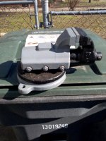
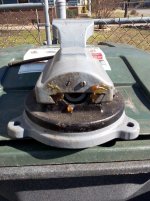
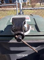
This is my story about a very challenging vise restoration. The vise is a FPU machinist's vise, manufactured by Bison-Bial in Poland, in the 1950s. I purchased it at a “pick” that I traveled 70 miles to. Paid 50$ for it. Not only did it have the normal amount of rust & coats of aerosol overhaul, it was missing a base foot and the swivel base lock handle. However, it had smooth movement and there were no other apparent defects.

Anyone would rightfully say that I'd be crazy for buying this broken vise for more than a couple of dollars. Here are the reasons that I purchased it:
1. It's a FPU, manufactured by Bison. Bison is a top shelf brand. It's an extremely well engineered vise that needed a home.
2. It looks cool, and has the movement that is reverse to the majority of bench vises.
3. Since it was made in Poland. There is a personal connection to it, as my Father was born there.
4. The challenge of this restoration: I've restored dozens of vises over the past 7 years. Most restorations are; disassemble, clean, polish, paint, lubricate & reassemble. I've also created bookends and other folk art with vises. Up until now, the biggest challenge was to free up a 100 year old Reed that had been setting outside in the mud for 20 years.

This restoration challenge is different because I want to do it without the use of equipment that wouldn't be available in the average garage (milling machine, lathe, welder, etc). The missing foot would have to be replaced without using a milling machine and OX/ACY torch and the missing swivel base handle would have to be made without a lathe.

On a side note, I would like to thank my GJ friend “mali” for teaching me the Polish word for vise: IMADLO. Also for his encouragement and links to the Polish online sellers' sites that feature pojawi się. I hope that I got that word right.
Thanks also to Drives and others for the encouragement and guidance.

For your review I've linked the Bison-Bial website here:
http://www.bison-bial.com/vises/machine-vises

Also the company history here: http://www.bison-bial.com/history

About my FPU vise:
FPU stands for FABRYKA PRZYRZADOW UCHWYTOW
(Google translation: Factory Tool Grip?)
Model #PJWK 80
Jaw size: 80mm (3.15”)
Jaw depth: 65mm (2.36”)
Maximum safe opening: 95mm (3.74”)
Overall weight: 12.25kg (27#)

This vise is similar to the Bison-Bial #1240-80, still manufactured today. Sometimes known as a dovetail vise. This leads me to wonder: What are the advantages and disadvantages of a reverse movement vise to the standard movement bench vise? I've brought this question on another thread and got some answers. If there are any vise experts that know, please reply.


Note: Some of the information here was already posted on the Vise Repair 101 thread to discuss some of the individual repairs.

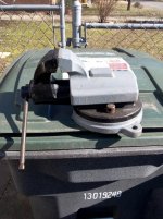
The pictures below is of my FPU vise as purchased, before disassembly:
 

Attachments

  • 1.FPU1.jpg
    1.FPU1.jpg
    147.3 KB · Views: 449
  • 1.1.FPU2.jpg
    1.1.FPU2.jpg
    146.1 KB · Views: 396
  • 1.2.FPU3.jpg
    1.2.FPU3.jpg
    147.6 KB · Views: 360
  • 1.3.FPU4.jpg
    1.3.FPU4.jpg
    148 KB · Views: 331
  • 1.4.FPU5.jpg
    1.4.FPU5.jpg
    147 KB · Views: 333
To avoid these ads, REGISTER NOW!
OP
M

Mark in Indiana

Well-known member
Joined
Aug 11, 2010
Messages
3,057
Location
Southern Indiana
FPU VISE BASE PROSTETIC FOOT REPAIR: 1 of 2


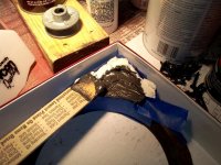
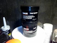
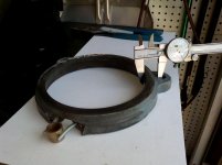
With the missing foot, I will need to create an inner skeleton, then mold a prosthetic foot for it using Devcon Liquid Steel. Again, although I could make a foot out of cast iron and braze it on, I wanted to perform a repair that didn't require any special equipment.

I used to make repairs to thermoforming molds and motor end bells using Devcon. It worked well. Will my repair last under normal use? It should, giving that the vise is small and the base is oversized for a 3"vise. I wouldn't try it with a large vise that would see an infinite amount of stress compared to my little FPU.


Below is the first group of pictures of the repair:

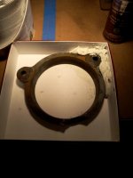
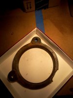
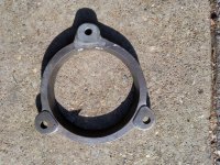
1. The bottom of the vise after disassembly, that shows the missing foot.

2. Make a plaster cast using a good foot.

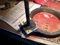
3. Drill & tap a couple of holes for the studs. Use thread lock on the studs. Drill some blind holes to help anchor the Devcon. Be sure to grind away any part of the studs that are sticking through the other side. That surface must be smooth.

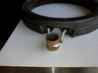
4. Grind some notches in a 1/2" ID bushing. The studs will rest in the notches. Apply some Devcon to the places where the bushing meets the studs to hold it all straight when you pour the rest of it.

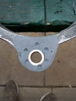
5. Measure where you want to locate the bushing so it will match the other feet.

6. The Devcon product that I used. Be sure to use it in a ventilated room. The stuff smells like rotten gym socks.

7. Attach the plaster mold, tape it well to prevent leaks, mix and apply the Devcon.


The rest of the pictures are in my next post.
 

Attachments

  • 8.BASE FIX6.jpg
    8.BASE FIX6.jpg
    147.2 KB · Views: 274
  • 7.BASE FIX5.jpg
    7.BASE FIX5.jpg
    143.7 KB · Views: 258
  • 6.BASE FIX4.jpg
    6.BASE FIX4.jpg
    126.7 KB · Views: 231
  • 5.BASE FIX3A.jpg
    5.BASE FIX3A.jpg
    144.3 KB · Views: 227
  • 4.BASE FIX3.jpg
    4.BASE FIX3.jpg
    139.2 KB · Views: 218
  • 3.BASE FIX2.jpg
    3.BASE FIX2.jpg
    125.4 KB · Views: 186
  • 2.BASE FIX1.jpg
    2.BASE FIX1.jpg
    134.2 KB · Views: 196
OP
M

Mark in Indiana

Well-known member
Joined
Aug 11, 2010
Messages
3,057
Location
Southern Indiana
FPU VISE PROSTETIC FOOT REPAIR: 2 of 2


From my previous post, I poured the Devcon into my plaster mold. Here are more pictures of what I did since then:

1. Break and scrape the plaster off. I forgot to mention that I taped up the bushing to keep the inner diameter clean. After that, I did a lot of hand sanding and filing on the top side, to get the new foot to look as close as I can to the others.
2. On the bottom side, the original feet had pads cast into them. I sanded down the bottom of the new foot and drilled some blind holes to anchor a new molded pad.
3. I cut a piece of cardboard to the shape of the foot pad and placed a 1/2" bolt in the bushing. I applied a thin coat of grease to the bolt and the top of my cardboard mold to keep the Devcon from sticking to them.
4. I mixed & poured in the Devcon on the bottom of the foot to make the pad.

5 & 6. After removing the cardboard mold & bolt, I sanded & filed the foot pad to get it to look as close as I can to the other feet. These 2 pictures are how the base looks before priming.

Now, off to the rest of the vise!
 

Attachments

  • 14.BASE FIX12.jpg
    14.BASE FIX12.jpg
    143.7 KB · Views: 237
  • 13.BASE FIX11.jpg
    13.BASE FIX11.jpg
    141.5 KB · Views: 241
  • 12.BASE FIX10.jpg
    12.BASE FIX10.jpg
    147.9 KB · Views: 227
  • 11.BASE FIX9.jpg
    11.BASE FIX9.jpg
    148.4 KB · Views: 232
  • 10.BASE FIX8.jpg
    10.BASE FIX8.jpg
    141.9 KB · Views: 248
  • 9.BASE FIX7.jpg
    9.BASE FIX7.jpg
    144.9 KB · Views: 250
OP
M

Mark in Indiana

Well-known member
Joined
Aug 11, 2010
Messages
3,057
Location
Southern Indiana
DISASSEMBLY

Now that the base is finished, it's time to disassemble the rest of the vise. Taking a reverse movement vise apart is as easy as a standard movement vise. All that needs to be done is to remove the 3 screws/nuts n the side, remove the 2 spindle nut screws at the back end, open the jaw far enough to remove the spindle from the nut, and slide the dynamic jaw away from the stationary jaw. As with anything, don't gorilla it with a BF hammer and a BF pry bar. I've heard of some guys who have broken the side of the dynamic jaw body.

1st Picture: The bodies easily came apart.

2nd Picture: All of the disassembled pieces.

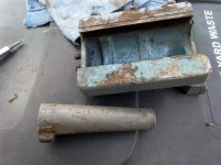
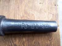
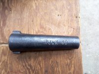
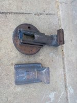
3Rd & 4th Picture: The spindle nut; Third picture shows the model number positioned on the bottom. Fourth picture shows some other stamped letters. I don't know what they mean.

5th Picture: The original paint was preserved. Looks like Rustoleum Hammered Verde.
 

Attachments

  • 18.FPU9 COLOR.jpg
    18.FPU9 COLOR.jpg
    146.8 KB · Views: 173
  • 17.1.FPU VISE NUT TOP.jpg
    17.1.FPU VISE NUT TOP.jpg
    147.9 KB · Views: 156
  • 17.FPU VISE NUT BOTTOM.jpg
    17.FPU VISE NUT BOTTOM.jpg
    147.4 KB · Views: 156
  • 16.FPU VISE DISASSEMBLED.jpg
    16.FPU VISE DISASSEMBLED.jpg
    144.2 KB · Views: 194
  • 15.FPU7.jpg
    15.FPU7.jpg
    146.5 KB · Views: 160
OP
M

Mark in Indiana

Well-known member
Joined
Aug 11, 2010
Messages
3,057
Location
Southern Indiana
PAINT PREPARATION

As this vise went through an aerosol overhaul, there were many coats of paint to deal with:

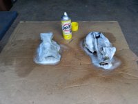
1st Picture; The stationary and dynamic jaw bodies are sprayed down with EZ-Off.
I let it soak for 5 – 6 hours because of chemical damage concerns. 8 – 10 hours will be fine and save some work with the wire wheel.

2Nd Picture: EZ OFF has been wiped off. Ready for the wire wheel.

3nd Picture: After some time on with the wire wheel, the bodies are all cleaned up. Oops! The edge of spindle cover, on the stationary jaw body looks damaged. There was some discussion about this on the Vise Repair 101 thread. Either that jagged edge was like that from the factory or it ended up on the wrong end of a BFH.

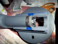
4rd Picture: I decided to mask & prime all of the bare metal to prevent flash rust.

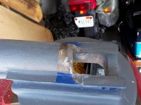
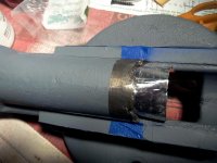
5Th Picture: Place some HVAC aluminum tape under the spindle cover as a dam and apply JB Weld to the edge.

6Th Picture: JB Weld has been poured. After cure time and some sand paper work, the repair will be complete,
 

Attachments

  • 25.FPU SPINDLE COVER REPAIR4.jpg
    25.FPU SPINDLE COVER REPAIR4.jpg
    141.7 KB · Views: 200
  • 24.FPU VISE SPINDLE COVER REPAIR3.jpg
    24.FPU VISE SPINDLE COVER REPAIR3.jpg
    147 KB · Views: 195
  • 23.FPU VISE SPINDLE COVER REPAIR2.jpg
    23.FPU VISE SPINDLE COVER REPAIR2.jpg
    142.4 KB · Views: 185
  • 22.FPU VISE SPINDLE COVER REPAIR1.jpg
    22.FPU VISE SPINDLE COVER REPAIR1.jpg
    140.4 KB · Views: 187
  • 21.FPU VISE PAINT CLEAN3.jpg
    21.FPU VISE PAINT CLEAN3.jpg
    146.1 KB · Views: 179
  • 20.FPU VISE PAINT CLEAN2.jpg
    20.FPU VISE PAINT CLEAN2.jpg
    144 KB · Views: 178
  • 19.FPU VISE PAINT CLEAN1.jpg
    19.FPU VISE PAINT CLEAN1.jpg
    140.8 KB · Views: 180
OP
M

Mark in Indiana

Well-known member
Joined
Aug 11, 2010
Messages
3,057
Location
Southern Indiana
PAINT DAY!

It's a nice hot, sunny day. Perfect for vise painting.

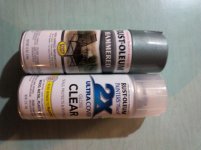
1st Picture: The paint & clear coat that will be used.

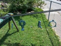
2nd Picture: All the pieces are hanging around waiting to dry.

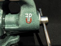
3rd Picture: Normally, my restorations include painting the embellishments a separate color from the body. I chose red & white for the FPU embellishment, which are the colors of the Polish flag.

4th Picture: WARNING! Rustoleum Painter's Touch 2X clear coat will react with Rustoleum Hammered paint, causing it to coarsely wrinkle like a Kennedy tool box finish, when the parts to clear coated are hot. I found this out by accident on a previous restoration. That's OK! The first coat of clear went on hot parts. After drying, I took them to a cool room, let the parts cool and sprayed on the rest of the clear coats.

Summary: This took several days to complete. There are 3 coats of Verde Green color and a S-Load of clear coats on this vise. Every coat went on first thing in the morning and last thing in the evening.
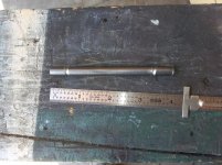
A few days for complete drying & cure time will take us to the vise reassembly.
 

Attachments

  • 26.FPU VISE PAINT.jpg
    26.FPU VISE PAINT.jpg
    125.2 KB · Views: 194
  • 27.FPU VISE PAINT DAY.jpg
    27.FPU VISE PAINT DAY.jpg
    149.8 KB · Views: 175
  • 28.RESTORED FPU15.jpg
    28.RESTORED FPU15.jpg
    139.3 KB · Views: 235
  • 29.FPU VISE PAINT2.jpg
    29.FPU VISE PAINT2.jpg
    151.5 KB · Views: 216
OP
M

Mark in Indiana

Well-known member
Joined
Aug 11, 2010
Messages
3,057
Location
Southern Indiana
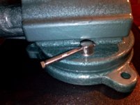
One of the major challenges of this vise is that the swivel base handle is missing. Fortunately, it's just the handle alone, not the bolt or the base stop (pulled up into the base to prevent movement when tightened).

Using a swivel base handle from a 150mm Bison-Bial vise as a model:
The handle is 7mm dia. Unfortunately, I couldn't fine a 7mm, plain bolt, with a long enough shank to make the handle. To solve that problem, I drilled out the hole in the vise's swivel base lock bolt (where the handle goes) and used a 5/16"-18 x 6", grade 8 machine screw. After that, I cut off the hex head and cut the threaded section off.

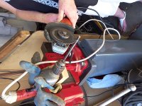
1st Picture; There is a groove cut at each end of the handle. Since I don't have access to a surface grinder with a spin jig, I secured an electric drill in my Parker vise and powered it using a variable voltage transformer (variac) to slow the drill down. Since the drill uses a brushed motor, this won't harm it. To cut the grooves in the ends, I used an*@#$angle*@#$grinder*@#$with a cut-off wheel.

2nd Picture; Finished with my "spin grinder". Now the grooves can be cleaned up with an aggressive wire wheel.

3rd Picture; The ends need to be flattened, horizontally in line with the shaft. Since this shaft came from a grade 8 bolt, it will need to be heated cherry red to shape the ends.*@#$

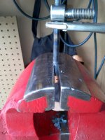
4th Picture; Immediately after heating an end, I crimped it with my Parker vise. This vise has smooth jaw faces and is heavy enough to do the job. Before crimping the second end, I placed the shaft in the hole of the swivel base lock bolt.
Note; I know that it's a NO-NO to use a vise as a press. However, cherry red steel is fairly soft, and the crimp wouldn't be as accurate by me, if I used a*@#$hammer*@#$& anvil.

5th Picture; New handle with the old one. I trimmed the handle ends, cleaned off burrs with a wire wheel and polished. At this time it's ready to be clear coated.

Side note about this task for this restoration:
As stated before, one of the standards for this restoration is that I wanted to use methods that didn't involve special equipment that's normally not found in a homeowner's garage (mill, lathe, welders, etc), to show that specialized equipment may not be necessary for a challenging restoration or repair. Because of the hardness of the bolt that I used to make the handle, I had to use an oxygen/acetylene torch in forming the ends. This is the only part of this restoration that I used specialized equipment on.


Now...Time for the vise reassembly!
 

Attachments

  • 34.FPU VISE BASE HANDLE5.jpg
    34.FPU VISE BASE HANDLE5.jpg
    154.4 KB · Views: 247
  • 33.FPU VISE BASE HANDLE4.jpg
    33.FPU VISE BASE HANDLE4.jpg
    142.2 KB · Views: 237
  • 32.FPU VISE BASE HANDLE3.jpg
    32.FPU VISE BASE HANDLE3.jpg
    142.2 KB · Views: 227
  • 31.FPU VISE BASE HANDLE2.jpg
    31.FPU VISE BASE HANDLE2.jpg
    144 KB · Views: 223
  • 30.FPU VISE BASE HANDLE1.jpg
    30.FPU VISE BASE HANDLE1.jpg
    107.1 KB · Views: 242
OP
M

Mark in Indiana

Well-known member
Joined
Aug 11, 2010
Messages
3,057
Location
Southern Indiana
REASSEMBLY

Now that the paint/clear coat has dried and the masking tape has been removed, it's time to reassemble this vise.

1st Picture: Stationary body is mounted to the base.

2nd Picture: The gib. Before attaching the dynamic body the stationary one, I will have to install the gib and adjustment screws. This is used to adjust the dynamic jaw for precise movement. The adjustment screws must be loose until the reassembly is complete. I will also have to set the spindle nut in place and install the two retaining screws.

For aesthetics, clear silicon grease is applied to the polished metal slides. EP2 bearing grease is applied to the spindle. The dynamic jaw body will then be installed on the body, spindle with retainer installed and the vise will need to be opened & closed several times to break away any overspray and ensure smooth movement.

3rd Picture: *The spindle nut retaining screws are screwed in so the screw tops are flush with the body and the spindle nut will somewhat float. If the screws are too tight, it will lock in the spindle nut and cause the dynamic jaw to bind.

4th Picture: *The 3 gib adjustment screws. Starting with the center one, tighten it down all the way. Then loosen it ¼ turn. Tighten the jamb nut. Do this with the two outer gib adjustment screws. You will notice the washers under the jam nuts. They are there to protect the paint.

* NOTE: If there is a reverse movement vise or FPU expert out there, please let me know if I calibrated this vise correctly.

5th Picture: Oops! The swivel base lock bolt is too tall to allow movement of the dynamic jaw body. This is because I added a bushing at the bottom of the lock bolt to protect the paint from the lock bolt when tightening. This is a feature that I add to all of my restorations. The bushing raised the bolt too much to allow dynamic jaw movement.
I will have to grind a little off the top & bottom of the bolt.

6th Picture: After some time with Mr. Grinder, the swivel base lock bolt is short enough to allow dynamic jaw movement.

7thPicture: Bottom of the vise base. I like how the 3 iron blocks lock into the inside bevel of the base at 3 points, when the lock bolt is tightened. IMO: Although not as solid as the drum brake swivel base lock design used on Chas. Parker vises, it's much better than the normal carriage bolt/nut swivel base lock design.
 

Attachments

  • 41.RESTORED FPU14.jpg
    41.RESTORED FPU14.jpg
    143.5 KB · Views: 215
  • 40.RESTORED FPU SWIVEL LOCK.jpg
    40.RESTORED FPU SWIVEL LOCK.jpg
    134 KB · Views: 192
  • 39.FPU VISE ASSEMBLY2.jpg
    39.FPU VISE ASSEMBLY2.jpg
    132.6 KB · Views: 191
  • 38.FPU VISE ADJUSTMENT2.jpg
    38.FPU VISE ADJUSTMENT2.jpg
    147.5 KB · Views: 204
  • 37.FPU VISE ADJUSTMENT1.jpg
    37.FPU VISE ADJUSTMENT1.jpg
    137.7 KB · Views: 197
  • 36.FPU VISE GIB.jpg
    36.FPU VISE GIB.jpg
    145.5 KB · Views: 188
  • 35.FPU VISE ASSEMBLY1.jpg
    35.FPU VISE ASSEMBLY1.jpg
    144 KB · Views: 227
OP
M

Mark in Indiana

Well-known member
Joined
Aug 11, 2010
Messages
3,057
Location
Southern Indiana
EPILOGUE

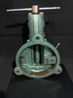
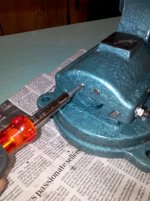
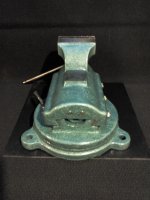
What I hope you all have been waiting for: Here is the fully restored FPU vise.


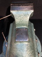
These pictures show different areas of the completed vise restoration.
You will notice that the blemishes on the anvil surface and the jaw tops have been preserved. I purposely do this on all of my restorations because they are part of the vise's character.


Summary: I hope that this thread were informative.
This vise was a privilege to restore and document. It's an honor to share it here.
Was this financially responsible? NO! However, it's more satisfying, cheaper and less frustrating than a golf outing. ;)


Happy Trails! Thanks for reading.
 

Attachments

  • 48.RESTORED FPU13.jpg
    48.RESTORED FPU13.jpg
    133.5 KB · Views: 256
  • 47.RESTORED FPU11.jpg
    47.RESTORED FPU11.jpg
    140.3 KB · Views: 271
  • 46.RESTORED FPU10.jpg
    46.RESTORED FPU10.jpg
    133.8 KB · Views: 284
  • 45.RESTORED FPU8.jpg
    45.RESTORED FPU8.jpg
    140.4 KB · Views: 277
  • 44.RESTORED FPU7.jpg
    44.RESTORED FPU7.jpg
    140.5 KB · Views: 309
  • 43.RESTORED FPU4.jpg
    43.RESTORED FPU4.jpg
    130.5 KB · Views: 330
  • 42.RESTORED FPU2.jpg
    42.RESTORED FPU2.jpg
    135.7 KB · Views: 339

sasquatch12

Well-known member
Joined
Nov 6, 2013
Messages
403
Hi Mark, i have that same vise that i picked up at a garage sale some years ago for $7.00. I find it to be a very smooth operating vise, and very well built. Only disadvantage with mine is you cannot mount it to hang over the edge of a bench to clamp shafts etc verticle due to the rear jaw moving. Still it is a good vise to use, so i hang onto it.
 

drivesitfar

Well-known member
Joined
Oct 23, 2013
Messages
36,047
Location
Pacific Northwest
MARK: first of all WELL DONE not only doing a great restoration, but for taking the time to take pictures and describe almost every detail. i have a few questions if you don't mind answering them i'd appreciate it.

1) how did you drill the hole in the swivel pin to make it larger? on a drill press sitting in a nice vise or do tell?
2) your set up with the drill in the vise using it like a lathe is far above my skills and if you have more details and pictures of that i'm sure others might want to know how to do that
3) wouldn't it have been easier to just remove the washer under the swivel pin instead of grinding the swivel pin's base about a 1/16 or 1/8th? i know you are saving the paint with the washer, but not sure that is a major concern there.
4) could there possible have been a way to only do one mold for the foot instead of two? it looks awesome BTW.

Also love the term aerosol overhaul

Again WELL DONE MARK and also if you'd like to post all this information on this thread and restoration over on the vise repair 101 thread I (WE) would appreciate it. thanks
 
OP
M

Mark in Indiana

Well-known member
Joined
Aug 11, 2010
Messages
3,057
Location
Southern Indiana
Drives & All,

I really appreciate the questions. Please see the answers below:

1) how did you drill the hole in the swivel pin to make it larger? on a drill press sitting in a nice vise or do tell?
A. I simply chucked the swivel pin in a vise with aluminum soft jaws and drilled out the hole from 7mm to 5/16", using a portable electric drill. Although the metal is soft, I used oil on the drill.

2) your set up with the drill in the vise using it like a lathe is far above my skills and if you have more details and pictures of that i'm sure others might want to know how to do that
A. The drill lathe is set up by securing a corded drill in a vise. It would be advised to add soft padding to keep the drill body from damage by the vise jaw faces. I connected my drill to a variable transformer known as a VARIAC (see picture). After placing the bolt shank in the drill chuck, I pulled the trigger on the drill, adjusted the motor to a very slow speed with the VARIAC, and proceeded to cut the grooves in the bolt shank with an angle grinder.

Although I used a VARIAC because I had one, a RHEOSTAT (or light dimmer) will do the same job. Here's a link that shows how to do it:


3) wouldn't it have been easier to just remove the washer under the swivel pin instead of grinding the swivel pin's base about a 1/16 or 1/8th? i know you are saving the paint with the washer, but not sure that is a major concern there.
A. Yes it would have been easier. However, with my restorations, I always add the bushing. Personally, for me, preserving the paint job for years is very important.

4) could there possible have been a way to only do one mold for the foot instead of two? it looks awesome BTW.

A. In retrospect maybe, but it would have been less controlled. The first part of molding the foot, I poured the Liquid Steel to where it was even with the rest of the bottom of the base. Then molded the foot pad. If I had dammed the first mold a little higher, I would have had to do a lot more filing and sanding to create the same foot pad shape as the other 2 feet. I also didn't think that I would have been able to create the entire foot & pad with 1 mold. Plaster or drywall mud is very fragile.

Thanks all for your kind words. I'll copy & paste my FPU vise restoration here so maybe more vintage iron vises can be saved from the scrap yard.
 

Attachments

  • VARIAC.jpg
    VARIAC.jpg
    5.2 KB · Views: 111
Last edited:

sk farmer

Well-known member
Joined
Mar 4, 2009
Messages
5,564
Location
nd
nice work. i just picked one of these up a few weeks ago. i thought it would need a repaint but after cleaning it looked pretty good. i was intrigued by the dove tail slide, the ability to lock it and the way the swivel locks.

and yes i know this is an old thread.
 
To avoid these ads, REGISTER NOW!
OP
M

Mark in Indiana

Well-known member
Joined
Aug 11, 2010
Messages
3,057
Location
Southern Indiana
Dave,
You're right. However, the point of restoring a vise like this one is to address the challenges of a broken vise, and to share the ways that these challenges were overcome. Also to learn about and share information/history about this vise.

SK,
Please show pictures of your FPU vise. They're always one of my favorite ones. Thanks for the compliment.

All,
I'm pleased to see this thread resurrected. Since posting this thread, the FPU vise is enjoying a leisurely life on display in my 1950s basement bar room.

In my search for the elusive FPU vises:
` I saw a 150mm FPU at an auction preview. The very day before this auction (which I could have easily dropped >3000$ on vises, tools & equipment), my wife injured herself. I had to take care of her.
` A few weeks ago I looked at a 125mm FPU that was on CraigsList. Although I quizzed the seller about it, I still went to see it. Part of the moving body at the dovetail was broken off. One of the weak points about this vise is that if you open it to capacity and really CRANK DOWN on your workpiece (using a cheater bar or hammering on the handle), the "turtle back" will break at the dovetail adjustment near the jaws.
As always, I hope the information in this thread helps someone with an restoration. And, thanks for the kind words.
 
Last edited:

KMScott

Well-known member
Joined
Feb 14, 2012
Messages
4,643
Location
Daufuskie Island, South Carolina
Mark, very nice restoration. It is so fulfilling to bring a vise back from the dead. Your repair work and steps are top notch. Keep up the good work. It is a great hobby where some do not get it.
 

pepi

Well-known member
Joined
Mar 27, 2013
Messages
2,883
Location
Woodstock, GA
Mark, very nice restoration. It is so fulfilling to bring a vise back from the dead. Your repair work and steps are top notch. Keep up the good work. It is a great hobby where some do not get it.

Some don't get it ? Reminds me of counterfeiting, not knocking the work ...... but it shows why I for one would never buy a "restored vise".

Apparently hobbiest think putty and body filler are suitable substitutes for a broken casting.

That totally fits the Ebay & craig list markets ....... not nice

greg
 
OP
M

Mark in Indiana

Well-known member
Joined
Aug 11, 2010
Messages
3,057
Location
Southern Indiana
Some don't get it ? Reminds me of counterfeiting, not knocking the work ...... but it shows why I for one would never buy a "restored vise".

Apparently hobbiest think putty and body filler are suitable substitutes for a broken casting.

That totally fits the Ebay & craig list markets ....... not nice

greg


Greg:
I appreciate your post and respect your opinion.

First.
A little background with regards to my vise restorations. Yes, I am a hobbyist. I've been restoring vises for 8 years. It's a personal pleasure to turn a blob of rust into a nice looking tool. Some for my collection, some to resell (to fund my hobby), some for customers who hire me to restore a family member's vise (ex. Grandpa's vise) and some for folk art projects (ex. bookends). I give full disclosure on any vise that is sold to or restored for a customer. A good reputation and trust are most important to me.
In the last few years, I have been acquiring broken vises for the challenge of making them whole again. Also, doing nothing more than clean / paint / polish / lubricate was getting repetitive.


I would like to address your statements with all due respects:
1. One of your statements; "Reminds me of counterfeiting, not knocking the work". Definition of counterfeiting; To make an exact imitation of something valuable or important with the intention to deceive or defraud. Where is my intent to deceive or defraud? My thread about this restoration left nothing hidden. I'm just showing an out-of-the-box way to repair a lower stress area of a small vise.

2. Another of your statements; "putty and body filler". I don't use Bondo. The product I used to make the repair has been used, by me successfully, to repair electric motor end bell bearing seat damage and thermoforming mold surface damage. I'm confident that with an inner skeleton, as shown in my thread, it will hold well as 1 of the 3 base feet, on a small vise.

3. Your final statement; "That totally fits the Ebay & craig list markets ....... not nice". I interpret that you're stating all sellers are shysters...and you're labeling my work with that. Ebay, CL, private sellers and all other markets have both good and bad players. In fact the majority of sellers are not dishonest. One of the things that I enjoy doing is pointing out the charlatans that will buy an old vise at a yard sale for 5$, rattle can it and expect to get >300$ for it. All they do is make the artisans who work hard to do an honest restoration a bad name.

I hope that you will take this post as nothing more than a respectful response to your comments.

Best Regards.
 

6PTsocket

Well-known member
Joined
Mar 12, 2014
Messages
4,593
Drives & All,

I really appreciate the questions. Please see the answers below:

1) how did you drill the hole in the swivel pin to make it larger? on a drill press sitting in a nice vise or do tell?
A. I simply chucked the swivel pin in a vise with aluminum soft jaws and drilled out the hole from 7mm to 5/16", using a portable electric drill. Although the metal is soft, I used oil on the drill.

2) your set up with the drill in the vise using it like a lathe is far above my skills and if you have more details and pictures of that i'm sure others might want to know how to do that
A. The drill lathe is set up by securing a corded drill in a vise. It would be advised to add soft padding to keep the drill body from damage by the vise jaw faces. I connected my drill to a variable transformer known as a VARIAC (see picture). After placing the bolt shank in the drill chuck, I pulled the trigger on the drill, adjusted the motor to a very slow speed with the VARIAC, and proceeded to cut the grooves in the bolt shank with an angle grinder.

Although I used a VARIAC because I had one, a RHEOSTAT (or light dimmer) will do the same job. Here's a link that shows how to do it:


3) wouldn't it have been easier to just remove the washer under the swivel pin instead of grinding the swivel pin's base about a 1/16 or 1/8th? i know you are saving the paint with the washer, but not sure that is a major concern there.
A. Yes it would have been easier. However, with my restorations, I always add the bushing. Personally, for me, preserving the paint job for years is very important.

4) could there possible have been a way to only do one mold for the foot instead of two? it looks awesome BTW.

A. In retrospect maybe, but it would have been less controlled. The first part of molding the foot, I poured the Liquid Steel to where it was even with the rest of the bottom of the base. Then molded the foot pad. If I had dammed the first mold a little higher, I would have had to do a lot more filing and sanding to create the same foot pad shape as the other 2 feet. I also didn't think that I would have been able to create the entire foot & pad with 1 mold. Plaster or drywall mud is very fragile.

Thanks all for your kind words. I'll copy & paste my FPU vise restoration here so maybe more vintage iron vises can be saved from the scrap yard.
Of the three, the Variac, the rheostat and the eletronic speed control, the speed control is cheapest and best for maintaining torque at low speed. Making one is a waste of time. You can buy one with a higher current rating than a lamp dimmer, as a router speed controller for under 20 bucks at Harbor Freight and quite a few other places under various brand names. The variac is a type of transformer that lowers the voltage. The rheostat is a variable resistor in series with the motor and pretty obsolete. The speed controller takes a piece out of each half of the sine wave by delaying turn on each time the voltage reverses direction. They work with any brush type motor.

Sent from my SM-G900V using Tapatalk
 

Agrove27

Well-known member
Joined
Aug 18, 2018
Messages
45
Location
Indiana
Great restoration! I just got done doing a hack job on a 6” FPU Bison and I’m also in southern Indiana, Evansville to be exact.
 

Agrove27

Well-known member
Joined
Aug 18, 2018
Messages
45
Location
Indiana
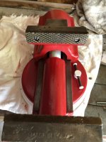
Here are some pics. I went with red and white from the Polish flag 🇵🇱 I picked this vise up for $50. Didn’t realize what I had until I stripped off the layers of black spray paint.
 

Attachments

  • 32C49412-2199-42B8-93FB-5CB837EBF71C.jpg
    32C49412-2199-42B8-93FB-5CB837EBF71C.jpg
    141.4 KB · Views: 106
  • 915F4799-9FE0-4E9C-AB82-B4F4AF2AC58E.jpg
    915F4799-9FE0-4E9C-AB82-B4F4AF2AC58E.jpg
    90.6 KB · Views: 95
  • 925D5795-F990-4818-B181-E0E41B9A9D56.jpg
    925D5795-F990-4818-B181-E0E41B9A9D56.jpg
    147.9 KB · Views: 116

fishwatcher

Well-known member
Joined
Jan 26, 2023
Messages
759
Awesome post and restore! I know I’m 8 years late in seeing this.

I particularly like how your project didn’t use shop tools not normally owned by the masses of DIYers.

A highlight for me was how you recreated the base foot not only with support rods but a cast and bushing. Great job!
 
Last edited:

FarmingGeek

New member
Joined
Oct 5, 2025
Messages
1
I know this was a long long time ago but I just picked up one of these at auction for pretty cheap but the Lead Nut missing almost completely. Just the piece that is bolted to the rear is remaining. I could probably make one myself but hoping someone knows the lead screw size or where I can get the lead screw nut/tube. The thing is in awesome shape, paint and all just that critical piece is missing.
 
To avoid these ads, REGISTER NOW!
Top Bottom