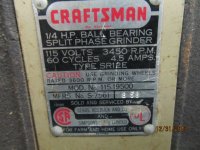
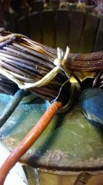
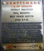
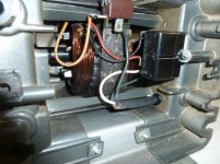
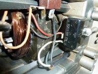
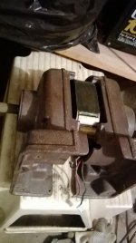
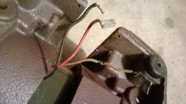
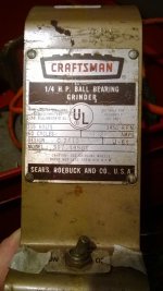
Bought a vintage CM block grinder the other day. The wiring needs some work, in fact I probably need to replace one of the wires (the white one in the pics) coming off the block. This thing is approx from 1960 and the pvc or whatever coating they used in the day is cracking and I can see a green patina on the copper wiring.
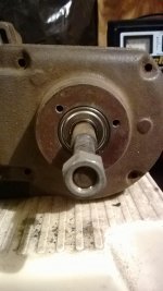
I've got all the bolts and screws out but I'm having trouble separating the halves. They seem to be press fit together. Any advice on how to do this (and put it back together?)
I've got all the bolts and screws out but I'm having trouble separating the halves. They seem to be press fit together. Any advice on how to do this (and put it back together?)

")

 )
)

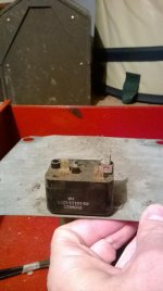
 Yes, remarkably enough there is a bottom cover plate but I didn't see a date stamp on it, will look again.