To avoid these ads, REGISTER NOW!

External Garage Lights...Linking to garage opener light circuit?

Tom R

Well-known member
Joined
Mar 23, 2008
Messages
77
Getting new doors and new door openers. Existing openers were wired so that the garage door opener turns on two external lights and also turns them off...they are linked to the single bulb circuit on the opener.

Turns out this was not something standard as provided for by the opener company. The previous owner must have found the internal power source to the opener bulb and wired it to the external lights.

Have had the linked lights for nearly 25 years and want the new set-up to work the same way. Some of you must have done this same "link"? Solutions?

1) Is there a brand of garage door openers that actually provide for such an option??

2) Has anyone else "linked" the garage door open bulb circuit to an external lighting resource??

What issues might I find if I have an electrician try to link...ie; find the timer circuit and wire up to the outside lights?

Thanks all...Tom R
 
To avoid these ads, REGISTER NOW!

s10xtremist

Well-known member
Joined
Aug 29, 2013
Messages
131
Location
State Capitol Raceway, LA
I tapped straight into the two wires going to the operator's single bulb socket to trigger a relay. I used a relay because I wasn't sure how many amps the operator's internal circuitry could support. This turns my main garage lights (two 8' twin bulb fluorescents) on instead of that one little bulb in the door operator. My wall switch is still connected (in parallel), so it still functions as normal:

 
OP
T

Tom R

Well-known member
Joined
Mar 23, 2008
Messages
77
I did this. I bought one of those bulb sockets that you can plug a grounded socket into and and wired my lights to that socket.

Kind of like this: http://www.homedepot.com/catalog/productImages/1000/fe/fec53c4e-b7c3-4c94-a8e3-626872bed67f_1000.jpg

Sent from my iPhone using Tapatalk

Amazingly simple! I would just need to turn the wires run from two outside garage lights into a plug. The wires are already there...just need to remove from the old unit and adapt to a plug...and of course get one of the socket adapters :)

Actually could make it work on the old opener first...rather than experimenting with the new closer. Thanks...Tom R
 
OP
T

Tom R

Well-known member
Joined
Mar 23, 2008
Messages
77
I tapped straight into the two wires going to the operator's single bulb socket to trigger a relay. I used a relay because I wasn't sure how many amps the operator's internal circuitry could support. This turns my main garage lights (two 8' twin bulb fluorescents) on instead of that one little bulb in the door operator. My wall switch is still connected (in parallel), so it still functions as normal:


Somehow I get the feeling this may be a "better" solution than the easy one above? Might protect the opener circuit board from high voltage? Since I may even be technically challenged to get the wires made into a plug in solution #1...not quite sure what a really is or how it applies? Thanks...Tom R

P.S. Do you think the socket solution above should work just fine...or some issues?? TMR
 

Drift_G35

Well-known member
Joined
Oct 27, 2010
Messages
71
I agree that the above solution is probably safer. However I had mine hooked up for 3 years before I sold my house with no issues. I also only had a mini halogen lamp hooked up to it and it was a brand new genie opener at the time. All that said, the few extra $$$ spent on the relay and other parts is probably worth it.


Sent from my iPhone using Tapatalk
 

wyliesdiesels

Well-known member
Joined
Aug 14, 2012
Messages
20,268
Location
Modesto, CA
Somehow I get the feeling this may be a "better" solution than the easy one above? Might protect the opener circuit board from high voltage? Since I may even be technically challenged to get the wires made into a plug in solution #1...not quite sure what a really is or how it applies? Thanks...Tom R

P.S. Do you think the socket solution above should work just fine...or some issues?? TMR

The relay would protect the opener control board from excessive amps or current NOT high voltage!

U can think of a relay as an electronic switch. When power is applied to the coil in the relay, it closes a switch and keeps it closed as long as theres power. Better solution than the socket adapter IMHO.
 

s10xtremist

Well-known member
Joined
Aug 29, 2013
Messages
131
Location
State Capitol Raceway, LA
^^^ Right. It's all ~110-120VAC. It's the current (amperage) load that I didn't want to place on the operator. I know those two fluorescent lights don't pull much amperage at all, but I would rather play it safe than sorry. The relay, socket, and wires are cheaper than a replacement control board, and way cheaper than the possible fire from overloading such a small circuit. Besides, I had the parts laying around. I wouldn't directly connect halogen light fixtures to the operator as they pull more current than the single standard bulb this operator was designed to power up. The wiring going to the bulb socket on my operator was quite small, indicating that it should not have a heavy load placed on it. With a relay, the operator's lighting circuit only "sees" the current that the relay's coil draws, which is merely milliamps- much less than the bulb it used to power. With a relay, the ampacity available to all the lights you want to power would basically be determined by the size of wiring and the breaker feeding them.
 

Von Psycho

Well-known member
Joined
Aug 12, 2014
Messages
297
Location
Holmes Hollow Ontario
In my house garage I put a bulb each side of the opener wired in place of the unit lights to light up each side of our vehicle rather than the top, it's all 110,same bulbs,just longer wires.
In the work shop I wired from the opener light wire to the soffit pot light to light up the exterior, 110. icandesent bulb, longer wire.
All the light functions obviously work the same as original.
Works for me, take care, Ralph...
 
OP
T

Tom R

Well-known member
Joined
Mar 23, 2008
Messages
77
Tom, If you're installing new openers and alter the Logic Board at all, it will VOID any warranties! Just saying. :beer:

I will stay away from the logic board. I think if you look at first suggestion that does not alter the board at all? Just take the opener light bulb and effectively power two outside lights triggered by the on off switch driven by the opener...merely plug your "extra" lights into the socket screw in device.

My current unit has essentially done that but has spliced in the wires rather than using the socket approach. Also, not sure how crowded the opener area where the light bulb resides.

I am not quite sure how the relay works.

Thanks...Tom R
 

wyliesdiesels

Well-known member
Joined
Aug 14, 2012
Messages
20,268
Location
Modesto, CA
^^^ Right. It's all ~110-120VAC. It's the current (amperage) load that I didn't want to place on the operator. I know those two fluorescent lights don't pull much amperage at all, but I would rather play it safe than sorry. The relay, socket, and wires are cheaper than a replacement control board, and way cheaper than the possible fire from overloading such a small circuit. Besides, I had the parts laying around. I wouldn't directly connect halogen light fixtures to the operator as they pull more current than the single standard bulb this operator was designed to power up. The wiring going to the bulb socket on my operator was quite small, indicating that it should not have a heavy load placed on it. With a relay, the operator's lighting circuit only "sees" the current that the relay's coil draws, which is merely milliamps- much less than the bulb it used to power. With a relay, the ampacity available to all the lights you want to power would basically be determined by the size of wiring and the breaker feeding them.

Dont forget, the available ampacity is also limited to the rating of the relay!

I will stay away from the logic board. I think if you look at first suggestion that does not alter the board at all? Just take the opener light bulb and effectively power two outside lights triggered by the on off switch driven by the opener...merely plug your "extra" lights into the socket screw in device.

My current unit has essentially done that but has spliced in the wires rather than using the socket approach. Also, not sure how crowded the opener area where the light bulb resides.

I am not quite sure how the relay works.

Thanks...Tom R

The problem with the adapter is its possible to overload the opener circuitry if too high of a wattage bulbs are connected to it. A relay is a fail safe solution that would protect the unit and its warranty.

I explained in #7 and s10 explained in #8 how a relay works . How can we explain it differently? Or what did we not explain? Would a picture help?
 
Last edited:

s10xtremist

Well-known member
Joined
Aug 29, 2013
Messages
131
Location
State Capitol Raceway, LA
To understand how a relay works, you must understand how a switch works since a relay is just a switch that is operated by electricity rather than moving a lever, pressing a button, etc. I'll try to make this as simple and direct as possible with some Google images.

Here's a simple switch diagram:

switch.jpg


Just think of it this way- you have two wires leaving your breaker panel and they're heading towards the light bulb. One is called the "neutral" and the other is the "hot" coming off of the breaker. The neutral goes to one terminal on the bulb completely uninterrupted. The hot wire goes to one terminal on the switch, then leaves the other terminal to continue on to the light bulb. Electricity must have a continuous and complete circuit for it to flow. If the wire is cut, the electricity can't flow through it. It doesn't shoot out the end of the cut wire like water does from an open hose. The switch is what "cuts" the circuit open to stop the flow of electricity. You move the lever up, and the metal contacts inside the switch connect one terminal on the switch to the other, completing the circuit so the electricity can flow to the light bulb and illuminate it. Simple, right?

Now, a relay does the same thing as far as the switching portion. But, instead of a mechanical lever, it has a solenoid that is energized by a different source of power. The purpose of a relay is to place the load onto a circuit that is designed to support it. By "load", I mean amperage. All electrical devices require a certain amount of amperage to operate. If the total number of amps on one circuit, whether it be from one device or many, exceeds the number of amps that the breaker will allow, then that circuit is what is called "over loaded" and the breaker will trip to prevent a hazard. Look at voltage and amperage as voltage being horsepower and the amperage being the torque. The horsepower is basically an operating number. What actually gets the job done is the torque. The torque is what pushes the power through the drivetrain and out to the wheels to propel the car. Or, in this case, the amperage is what pushes through the wires to illuminate that bulb or spin that motor. The problem is that the conductors (the wires) must be large enough to let the amount of amps push through. The wires coming off of the Logic Board send 120 volts to the bulb, but they are only big enough to support the amount of amperage that bulb places on the circuit. Of course, there is a certain amount of headroom as a safety factor. Due to this safety factor, it may be robust enough to power one or two more similarly-sized lights, but it is still essentially "over loaded". It's just not over loaded enough to heat up the wiring enough to start a fire or burn that portion of the Logic Board. At least not in the short time periods that it's actually turned on.

With a relay, the hot wire feeding the bulb(s) is cut by the contacts in the relay (the switching portion of it). The coil in the relay is what moves the contact to cut ("open") or complete ("close") the circuit. The power that went to the bulb on the operator is now just powering this small col in the relay. Instead of the electricity going through a filament in the bulb to heat up and create light, it's merely going through a coil to create a magnetic field that moves the contactor inside the relay. This is an even smaller load for the operator than what the bulb was.

This is about the simplest pic I could find:

AB45FBA.gif


Referring to how this diagram is drawn and labeled, the operator's light circuit sends power to the coil inside the relay. This is the "Command" and "Ground or Hot" labels. The two wires that went to the bulb on the operator would go to these two. The energized coil moves a contactor, labeled as "pivot", to connect the two contacts (the red ovals). This completes the circuit, letting the electricity that's coming into the relay on the "Hot" terminal, pass on to the extra lights connected to the "Load" terminal.


BTW, for you engineers and smarter people, I realize the horsepower/torque relation isn't exactly the most accurate. But, coming from a car guy, that's the best way I could explain it in a simple form.
 

Steevo

Well-known member
Joined
Aug 18, 2009
Messages
8,738
Location
43.49600, -112.04300
I had a previous garage wired with the relay solution. In my case, the relay could be tripped by either the GDO light power, or a wall switch, and it powered six dual-tube fluorescent fixtures in the garage. When you hit that GDO remote, the whole place lit up.
 

s10xtremist

Well-known member
Joined
Aug 29, 2013
Messages
131
Location
State Capitol Raceway, LA
^^^

Exactly why I did mine. I have dark tint and backing into my garage at night was a PITA. By the time I was close enough to see where I needed to turn, I was too close and had to pull forward again. Rolling the windows down helped, but that was only on nights that it wasn't raining. I ran the two wires off the relay to to the two terminals on the wall switch, so it's just like having another switch connected in parallel. The garage light switch works just like always.
 
OP
T

Tom R

Well-known member
Joined
Mar 23, 2008
Messages
77
Thanks S10...I kind of understand this...I guess I do need a "picture" :)

Seems like the relay is the best choice...my daughter does have an electrician boyfriend that could probably make sure I didn't burn the garage down...or just ruin the circuit board.

Other choice of the socket adapter? Does pcpro15's suggestion to go to LED lighting "solve" the amperage issue? IF I used the socket adapter (the one with its own bulb shown earlier in the thread)...but used three LED bulbs (one on the opener and two external)...would the LEDs assure I would not "blow" the circuit board? Could I use any size LEDs?

What I have now is external light wires wired into the old garage door opener...must have spliced inside the opener. Work with me. Would I wire the external wires to one side of the relay...the non-"coil" side???

Then how would I get the opener circuit connected to the coil(?) side...if I understand the relay?

Maybe I need to look at a relay to understand if it has a plug in our ????

Would I work off the opener light socket or off the opener power circuit plug in??

Sorry for the ignorance...my electrical ability i basically installing lighting into an existing light "box".

Thanks...Tom R


To understand how a relay works, you must understand how a switch works since a relay is just a switch that is operated by electricity rather than moving a lever, pressing a button, etc. I'll try to make this as simple and direct as possible with some Google images.

Here's a simple switch diagram:

switch.jpg


Just think of it this way- you have two wires leaving your breaker panel and they're heading towards the light bulb. One is called the "neutral" and the other is the "hot" coming off of the breaker. The neutral goes to one terminal on the bulb completely uninterrupted. The hot wire goes to one terminal on the switch, then leaves the other terminal to continue on to the light bulb. Electricity must have a continuous and complete circuit for it to flow. If the wire is cut, the electricity can't flow through it. It doesn't shoot out the end of the cut wire like water does from an open hose. The switch is what "cuts" the circuit open to stop the flow of electricity. You move the lever up, and the metal contacts inside the switch connect one terminal on the switch to the other, completing the circuit so the electricity can flow to the light bulb and illuminate it. Simple, right?

Now, a relay does the same thing as far as the switching portion. But, instead of a mechanical lever, it has a solenoid that is energized by a different source of power. The purpose of a relay is to place the load onto a circuit that is designed to support it. By "load", I mean amperage. All electrical devices require a certain amount of amperage to operate. If the total number of amps on one circuit, whether it be from one device or many, exceeds the number of amps that the breaker will allow, then that circuit is what is called "over loaded" and the breaker will trip to prevent a hazard. Look at voltage and amperage as voltage being horsepower and the amperage being the torque. The horsepower is basically an operating number. What actually gets the job done is the torque. The torque is what pushes the power through the drivetrain and out to the wheels to propel the car. Or, in this case, the amperage is what pushes through the wires to illuminate that bulb or spin that motor. The problem is that the conductors (the wires) must be large enough to let the amount of amps push through. The wires coming off of the Logic Board send 120 volts to the bulb, but they are only big enough to support the amount of amperage that bulb places on the circuit. Of course, there is a certain amount of headroom as a safety factor. Due to this safety factor, it may be robust enough to power one or two more similarly-sized lights, but it is still essentially "over loaded". It's just not over loaded enough to heat up the wiring enough to start a fire or burn that portion of the Logic Board. At least not in the short time periods that it's actually turned on.

With a relay, the hot wire feeding the bulb(s) is cut by the contacts in the relay (the switching portion of it). The coil in the relay is what moves the contact to cut ("open") or complete ("close") the circuit. The power that went to the bulb on the operator is now just powering this small col in the relay. Instead of the electricity going through a filament in the bulb to heat up and create light, it's merely going through a coil to create a magnetic field that moves the contactor inside the relay. This is an even smaller load for the operator than what the bulb was.

This is about the simplest pic I could find:

AB45FBA.gif


Referring to how this diagram is drawn and labeled, the operator's light circuit sends power to the coil inside the relay. This is the "Command" and "Ground or Hot" labels. The two wires that went to the bulb on the operator would go to these two. The energized coil moves a contactor, labeled as "pivot", to connect the two contacts (the red ovals). This completes the circuit, letting the electricity that's coming into the relay on the "Hot" terminal, pass on to the extra lights connected to the "Load" terminal.


BTW, for you engineers and smarter people, I realize the horsepower/torque relation isn't exactly the most accurate. But, coming from a car guy, that's the best way I could explain it in a simple form.
 

s10xtremist

Well-known member
Joined
Aug 29, 2013
Messages
131
Location
State Capitol Raceway, LA
Thanks S10...I kind of understand this...I guess I do need a "picture" :)

I'm a picture studier/hands-on learner myself.

Seems like the relay is the best choice...my daughter does have an electrician boyfriend that could probably make sure I didn't burn the garage down...or just ruin the circuit board.

Run the idea by him and he'll know exactly what you need. Maybe show him my pic. Relays like that are available at any supply house. Have him hook it up for you, but watch and learn or even help him if he allows.

Other choice of the socket adapter?

What you talkin' bout, Willis?

Does pcpro15's suggestion to go to LED lighting "solve" the amperage issue?

Probably, but I've never looked up the amperage of that style of bulb. But, you would be limited to using only LED bulbs in those fixtures. I don't have any firsthand experience with LEDs used as outdoor lights other than the super expensive commercial fixtures. The ones designed to be a direct replacement for a standard screw-in bulb put out nowhere near the lumens of those. Also, I would assume for an outside light you would want a flood design. LEDs don't have a very wide light dispersement.

IF I used the socket adapter (the one with its own bulb shown earlier in the thread)...but used three LED bulbs (one on the opener and two external)...would the LEDs assure I would not "blow" the circuit board?

Would probably be ok. But, it would depend on the type and wattage of LED bulb you get.

Could I use any size LEDs?

Technically, no. But, probably just about any of the medium base screw-in bulbs available at the big box stores would be fine. Keyword: probably

What I have now is external light wires wired into the old garage door opener...must have spliced inside the opener. Work with me. Would I wire the external wires to one side of the relay...the non-"coil" side???

The wires that feed the light bulb on the operator would feed the coil on the relay. If you don't want to cut and splice into your operator, you can get that adapter that Drift_G35 linked to and plug a cheap extension cord into it. Cut off the other end and terminate it to the relay. Remember, you want the operator to trigger a relay (energize it's coil) instead of powering multiple lights. The lights will draw X number of amps, and may be too much for the operator to support, whereas the relay's coil will draw only milliamps- less than what it's original bulb pulled.

Then how would I get the opener circuit connected to the coil(?) side...if I understand the relay?

You're not quite getting it, or thinking backwards. You want the external lights to get 120V when the bulb on the operator gets 120V. So, you use the power that feeds the bulb on the operator to trigger the relay (the coil).


Maybe I need to look at a relay to understand if it has a plug in our ????

The relay plugs into a special socket, and the socket has all of the termination points on it that correspond with the relay's terminals.


Would I work off the opener light socket or off the opener power circuit plug in??

You would use the operator light socket power to trigger the relay. The power to feed the external lights can come from the receptacle that the operator is plugged in to, or from another 120V source if it's more convenient. Do you already have the external fixtures in place? If so, are they on a switch?


Sorry for the ignorance...my electrical ability i basically installing lighting into an existing light "box".

Everyone has to learn somehow, and electrical stuff is always handy knowledge. You're probably just over-thinking all of this. We'll get it.
 

pcpro15

Well-known member
Joined
Mar 22, 2011
Messages
390
Other choice of the socket adapter? Does pcpro15's suggestion to go to LED lighting "solve" the amperage issue? IF I used the socket adapter (the one with its own bulb shown earlier in the thread)...but used three LED bulbs (one on the opener and two external)...would the LEDs assure I would not "blow" the circuit board? Could I use any size LEDs?

What I have now is external light wires wired into the old garage door opener...must have spliced inside the opener. Work with me. Would I wire the external wires to one side of the relay...the non-"coil" side???


Yes, it does solve the amperage issue.

1 incandescent 60w bulb 800 lumens
60w/120v = .5 amp

3 LED 100w - 1600 lumens
18w draw / bulb

(18w x 3bulbs) / 120v = .45 amp

I posted the other socket because I was unsure if there was enough room in the opener to add that and a bulb. If you find there is no room, use the adapter I posted earlier. Add a lamp base to your ceiling to add your 3rd bulb.

The 100w bulbs will double your normal lumens. Using 3 100w LED bulbs will still be in line (a hair less) amperage wise to a single standard 60w bulb.

http://www.homedepot.com/p/Cree-100...ght-Bulb-BA21-16050OMF-12DE26-1U100/205054836

The other suggestions posted are valid as well. Just depends how you would like to do it. Good Luck
 
To avoid these ads, REGISTER NOW!

s10xtremist

Well-known member
Joined
Aug 29, 2013
Messages
131
Location
State Capitol Raceway, LA
^^^ Good info to know about those LED bulbs. I was thinking of the outdoor flood light style bulbs, which have numerous styles of the LED version, so I didn't bother elaborating on those.

Tom, before investing $75 in bulbs, buy just one of them and see how well it lights the area you want. I'm not discounting those LED bulbs at all, I just haven't looked into them in a while. The ones I reviewed were disappointing.
 

s10xtremist

Well-known member
Joined
Aug 29, 2013
Messages
131
Location
State Capitol Raceway, LA
Regardless of which way you go with your external lights, I wanted to post up pics to give you a better understanding of the relay stuff:

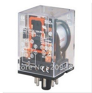
This is the style of relay I used, note the diagram printed on the relay:

OMRON-MK2P-I-AC-220V-Relay-8-Pin-10A-250VAC-With-PF083A-Socket-Base.jpg


It has 8 pins in a radial pattern on the bottom that plug into a socket. The socket has numbered terminals that correspond with the relay. Socket:

5057612.jpg


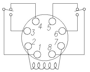
This is how the terminals on the relay are laid out:

round-relay-pinout.jpg


The relay's coil is terminals 2 and 7. The wires that power the operator's bulb would go to these two terminals. This is what triggers the relay, or "energizes the coil".

You have two sides to connect to on this type of relay because it is a "double pole". This is for extra flexibility in connections, such as closing one circuit while simultaneously opening another. You would only need to use one side- terminals 1,3,and 4 or terminals 8, 6, and 5. Terminals 1 or 8 is where the hot wire that feeds the external lights would go to. This is the equivalent to one terminal on a regular light switch. Terminals 4 or 5 are what's called "normally closed". These terminals are always connected to terminals 1 and 8 when the relay is "at rest" (coil not energized). If you ran the hot wire from either 4 or 5, the external lights would always be on until the relay was triggered. This would result in the lights turning off when the light on the operator was turned on, and vice-versa. So, you would connect the hot wire that feeds the external lights to either terminals 3 or 6, the "normally open" terminals. When the coil is energized, it's like that little lever on 1 or 8 moves off of 4 or 5, and onto 3 or 6. This is just like you flipping a light switch to close the circuit so the electricity can flow to the lights.
 
Last edited:

Elmo4895

Well-known member
Joined
Jul 22, 2014
Messages
54
Location
Natchez, MS
If it were me I would use the relay and the extension that S10 described. Lots more choice in bulbs and absolutely no changes to the opener circuit. Probably cheaper than led bulbs and will be capable of putting out a lot more light.
 
OP
T

Tom R

Well-known member
Joined
Mar 23, 2008
Messages
77
S10...thanks for the amazing narrative. I believe the relay approach is the best solution to both protect the circuit board and allow open selection of lights. I will probably need my daughter's electrician boy friend to help me sort though your notes. In the meantime...maybe a couple of clarifications...

1) Does the relay become an "in-line" item...maybe as a fuse might?

2) If 1) is correct then I assume one one "side" you have the external lights and on the other "side" you have the switching and power input from the garage door opener??

3) I assume you mount the relay base and then attach wires (after fully understood)...plug the active relay into its base?

If the above is correct or close there may be some hope for me :) IN any case I also want to wire in an on/off switch...for use w/o using the opener to turn on the external lights...that is missing from the current set-up...I will seek advice as I mentioned and get it done correctly and well...my "freebie" electrician is an electrical contractor and very experienced...unlike me :)

Let me know if I am beginning to get the point...I hope I am taking this pass/fail as I have little hope for a good grade...Tom R

Regardless of which way you go with your external lights, I wanted to post up pics to give you a better understanding of the relay stuff:

This is the style of relay I used, note the diagram printed on the relay:

OMRON-MK2P-I-AC-220V-Relay-8-Pin-10A-250VAC-With-PF083A-Socket-Base.jpg


It has 8 pins in a radial pattern on the bottom that plug into a socket. The socket has numbered terminals that correspond with the relay. Socket:

5057612.jpg


This is how the terminals on the relay are laid out:

round-relay-pinout.jpg


The relay's coil is terminals 2 and 7. The wires that power the operator's bulb would go to these two terminals. This is what triggers the relay, or "energizes the coil".

You have two sides to connect to on this type of relay because it is a "double pole". This is for extra flexibility in connections, such as closing one circuit while simultaneously opening another. You would only need to use one side- terminals 1,3,and 4 or terminals 8, 6, and 5. Terminals 1 or 8 is where the hot wire that feeds the external lights would go to. This is the equivalent to one terminal on a regular light switch. Terminals 4 or 5 are what's called "normally closed". These terminals are always connected to terminals 1 and 8 when the relay is "at rest" (coil not energized). If you ran the hot wire from either 4 or 5, the external lights would always be on until the relay was triggered. This would result in the lights turning off when the light on the operator was turned on, and vice-versa. So, you would connect the hot wire that feeds the external lights to either terminals 3 or 6, the "normally open" terminals. When the coil is energized, it's like that little lever on 1 or 8 moves off of 4 or 5, and onto 3 or 6. This is just like you flipping a light switch to close the circuit so the electricity can flow to the lights.
 

s10xtremist

Well-known member
Joined
Aug 29, 2013
Messages
131
Location
State Capitol Raceway, LA
1) Does the relay become an "in-line" item...maybe as a fuse might?

On the coil side, no. The switched side, yes. Power goes to a bulb into one side, travels through the filament (which heats up and creates light), then out of the other side into the other wire. On the coil side of a relay, power goes into it on one terminal, travels through the coil (which creates a magnetic field to move a solenoid), then out of the other side through the other wire. If you want, look at the relay as being just another very tiny bulb plugged into the operator's light. The coil in the relay is the only additional load the operator's light circuit will "see", which is virtually nothing at all.

On the switched side of the relay, it's just like that- a switch. You have power coming from the source (breaker, receptacle circuit, etc.) with two wires- a hot and a neutral. The neutral goes straight to the light(s). The hot goes to one side of the relay just as it would go to one side of the switch. The hot continues out of the other side of the relay and goes to the light(s), just the same as it continues out the other side of the switch and goes to the lights.

2) If 1) is correct then I assume one one "side" you have the external lights and on the other "side" you have the switching and power input from the garage door opener??

Exactly. The relay is a switch, plain and simple. Only instead of you manually flipping a small lever to connect the contacts inside of it to let the electricity flow, you are using an electric signal from a device to connect the contacts inside of it to let the electricity flow.

3) I assume you mount the relay base and then attach wires (after fully understood)...plug the active relay into its base?

Yes. The base is so the relay can be mounted and terminated but also be easily removed and/or replaced as necessary without having to disconnect wires. You simply determine what wire goes what numbered terminal on the relay, then terminate the wire to that same number on the base. When you plug the relay in, whatever wire is terminated on #1 on the base will be connected to the #1 terminal on the relay, #2 with #2, etc.

IN any case I also want to wire in an on/off switch...for use w/o using the opener to turn on the external lights...that is missing from the current set-up...I will seek advice as I mentioned and get it done correctly and well...my "freebie" electrician is an electrical contractor and very experienced...unlike me :)

Really, you can just install the external lights how they are supposed to be in the normal way- switch and all. Then, run two wires from the relay to the terminals on the switch that feeds the external lights. It would be like having two switches in different locations that feed the same lights, powered off the same circuit. This is not to be confused with a 3-way switch setup. My garage lights are wired up the way I just described. They are fed off a wall switch on the inside by the door. I just ran the two wires from the relay I mounted by the operator, along the rafter in the attic (it was only about a 12' run), and down through the top plate of the wall and to the switch box. I had to bust a bigger hole in the top of the box to get the Romex in, but the boxes are a type of brittle plastic the make this easy.

Let me know if I am beginning to get the point...I hope I am taking this pass/fail as I have little hope for a good grade...Tom R

I think you're starting to understand. Once you do, you'll realize how simple a concept it really is, then it'll be burned into your mind. I've explained it a few different ways, something's bound to stick. :lol_hitti
 

voda1

Member
Joined
Mar 25, 2011
Messages
7
...
Then, run two wires from the relay to the terminals on the switch that feeds the external lights. It would be like having two switches in different locations that feed the same lights, powered off the same circuit. This is not to be confused with a 3-way switch setup.

Confused. Could you post up a wiring diagram?
 

s10xtremist

Well-known member
Joined
Aug 29, 2013
Messages
131
Location
State Capitol Raceway, LA
Confused. Could you post up a wiring diagram?

If I can find a program on this iMac like MS Paint, I could throw together a simple drawing. This iMac is my wife's computer, and all I do with it is use Firefox. I don't browse through the programs as it has a bunch of programs with names that do nothing that the name insinuates.

Picture it this way. You may even need to draw it out as you read it:

Two regular identical light switches placed side by side. Each switch has two terminals, one on top and one on bottom, that are connected or disconnected internally when the switch lever is moved. In a standard installation, the hot wire comes to one terminal, then leaves the other terminal to go to the light. Now, run a wire from the bottom terminal of the first switch to the bottom terminal of the second switch. Run a wire from the top terminal of the first switch to the top terminal of the second switch. Nothing has changed with the first switch. It still has a hot wire coming to it and a hot wire leaving it. With the first switch lever down, the power can't flow because the terminals aren't connected inside the switch. Now, flip the lever on the second switch up. The power that is coming in to one terminal is also going to the terminal on the second switch, so the power can flow through that switch to it's other terminal, which is also connected to the other terminal of the first switch. So, the power flows through and feeds the light. It's like you have a second switch to bypass the first one. If both are off, the light is off. If either or both are on, the light is on. They are being fed by the same source, so there is no phase issue. That relay is just a second switch, only it isn't activated by flipping a plastic lever with your finger. It's activated by voltage coming from the door operator.
 

Spudland_Dave

Well-known member
Joined
Mar 12, 2010
Messages
3,025
Location
Maine
Excellent Writeup, and I think I will be attempting this Soon. Could you help us out on specs/pn#'s etc on the relay you used? In my case I would need mutiple inputs
1 Wall Switch and 2 Light Inputs from Garage Door Opener "feed"

So if I understand this correctly...operating any ONE of the switches (I'm also calling the GDO a switch) will energize the lights. Any issues with energizing multiples switches at once...so for example if you already had the lights on via wall switch and you activate a GDO.

Thanks Again!
 

s10xtremist

Well-known member
Joined
Aug 29, 2013
Messages
131
Location
State Capitol Raceway, LA
Excellent Writeup, and I think I will be attempting this Soon. Could you help us out on specs/pn#'s etc on the relay you used? In my case I would need mutiple inputs
1 Wall Switch and 2 Light Inputs from Garage Door Opener "feed"

So if I understand this correctly...operating any ONE of the switches (I'm also calling the GDO a switch) will energize the lights. Any issues with energizing multiples switches at once...so for example if you already had the lights on via wall switch and you activate a GDO.

Thanks Again!

No issues are possible because the lights are being powered by the exact same source. It has the original wall switch to open/close the circuit, but it will also have another switch on the same circuit to open/close the circuit.

It's just like one of these splitters for a water hose:

297419.jpg


One hose comes into it from the spigot (one single source), then multiple hoses branch off of it. Only the two hoses branching off of it are going to one sprinkler. If you turn on side on, water will flow to the sprinkler. Turn that side off and then turn the other side on- same thing. Or, turn both sides on- makes no difference because it's all water coming from the same source.


I was able to find a crappy sketch program online. At the bottom of the pic is a black and light gray wire. This is the hot and neutral that feeds the light. The neutral goes straight to the light. The hot goes to one gold terminal on the wall switch, then leaves the other gold terminal to continue on to the light. Flipping the switch up connects these two gold terminals so the power can flow to the light. The green blob is the garage door operator. The two wires coming off of it are the two wires that feed it's built-in light. These wires go to the coil of the relay (the blue square with the switch symbol in it). When the garage door operator sends power through it's two wires as it would to illuminate it's built-in light, it sends power through the coil of the relay. This makes the relay connect it's two gold terminals, doing the exact same thing as the wall switch. If the wall switch is up ("ON"), power is flowing to the light. If the wall switch is down, power can not flow to the light. If the relay is energized, the power "bypasses" the wall switch and continues to the light. If the wall switch is on, and the relay is energized (same as switch being "ON"), it will make no difference since the power is still getting to the bulb. It's just going through some extra wiring. Trace the "flow" of the electricity as you read this description if it'll help.
 

Attachments

  • paint.jpg
    paint.jpg
    54.6 KB · Views: 37
Last edited:

s10xtremist

Well-known member
Joined
Aug 29, 2013
Messages
131
Location
State Capitol Raceway, LA
I can't get my ladder under the relay I'm using with my wife's car in the way, but I have a similar one in my cabinet that would work just the same.

The relay is a Dayton brand, model 5X824M
The socket is a Time Mark brand, model 51x120

On this particular relay, you would connect the wires from the garage door operator's light to terminals 2 and 7, polarity doesn't matter. Then, you would run wires (piece of Romex, etc.) from terminals 1 and 6 to the terminals on the wall switch, no polarity here, either. Anything the wall switch controls will also be controlled by the garage door operator. Simple as that.
 

lerxst01

New member
Joined
Jan 30, 2019
Messages
2
Location
Germantown, MD
s10xtremist,

I'm trying to wire lights to my garage door opener like you indicated in this thread. I've looked for a relay like the one you have in the picture, but I can't find one that is similar online. Does the relay actually plug into an outlet or did you put a couple of things together to make what you have pictured?

Could you provide a link as to where to purchase the relay you used?

Thanks much!
 

wes73

Well-known member
Joined
Nov 18, 2013
Messages
218
Location
South Central PA
Liftmaster as a wall switch 823LM that can be synced with a Liftmaster opener, or a button on the remote, and can even be schedule through their MyQ web enabled app. I have two switches that are on a schedule, not synced with my opener. I preferred this since it adds a little more security. Check out the instructions for the 823LM. https://www.liftmaster.com/catalogresourcesv3/en-us/shared/files/tucmanuals/114a4349.pdf

Perhaps you can wire your lights to the 823LM and then have different options.
 

Dishpointer

Member
Joined
Aug 9, 2014
Messages
11
Location
Kansas
Liftmaster as a wall switch 823LM that can be synced with a Liftmaster opener, or a button on the remote, and can even be schedule through their MyQ web enabled app. I have two switches that are on a schedule, not synced with my opener. I preferred this since it adds a little more security. Check out the instructions for the 823LM. https://www.liftmaster.com/catalogresourcesv3/en-us/shared/files/tucmanuals/114a4349.pdf

Perhaps you can wire your lights to the 823LM and then have different options.

I have this switch and it works perfectly to control the led lights in my garage. It will turn everything on just like a light switch or any time you use the door remote and will automatically turn off 10 minutes after the door is shut.
 

sberry

Banned
Joined
Jun 18, 2005
Messages
35,747
Location
Brethren, Michigan
Modern lights are now 1/4 the current its designed for and used 25 yrs ago, lots of 100 watt lamps on it. If I was doing this cause I don't know squat would simply extend the wires to some fixtures with LED. Mosto that stuff is wired with the same parts from a motion detector.
That is just one design option. Personally would run some wire to a couple fixture locations. I might even put some on a timer if everyone is in bed all tidy but low wat LED isn't even worth fukkin with turning a switch on for or hook them thru a timer. I have about 6 small cfl run in optimum locations and a couple motion detectors that light doors and walk ways. I might add in a switch some place convenient for other options.

There is nothing wrong with relays but photo cell and timer along with a fixed nightlight and entrance exit with extra basic motion. In a common garage the runs are so close would simply wire each fixture to a box and hookem or switch each I wanted.
I just did a job to a small apartment and the guy wants the minimum, ok, but by the time it was done he could see the logic to 3 wire to all the fixtures if I am using cable.
 

sberry

Banned
Joined
Jun 18, 2005
Messages
35,747
Location
Brethren, Michigan
I like 14 for lights and a run to a fixture with power lets automatic features be installed along with a switch wire or,,, to be able to extend from those boxes later in some cases.
 

sberry

Banned
Joined
Jun 18, 2005
Messages
35,747
Location
Brethren, Michigan
What I was trying to say was I would leave the opener stock and tailor the other lights to do what I wanted.
I have moved the night lights a couple times but I have 3 and sometimes 4 that give enough light I can walk building to building without any active switching. The garage door to my parents is the service door used and I have a motion detector on the back wall aimed out so as you enter the garage the small task light has led the way and then motion detector turns on an overhead so you can see step and door. I got it hyper set so when heaving the house you wo0uld swear its connected to the door knob so its lit on the way out.
 
Last edited:
To avoid these ads, REGISTER NOW!
Top Bottom