To avoid these ads, REGISTER NOW!

How to wire a 24v Thermostat?

RonRock

Well-known member
Joined
Oct 6, 2007
Messages
1,171
Location
Iowa, USA
Subject beaten to death I'm sure. But mine is a special situation.

So I have a Reznor waste oil burner in my shop. It now has a thermostat that is simply a switch. No transformer. Just a wall mounted thermostat with 2 wires. Thermostat simply closes the circuit on a call for heat.

I want to change the thermostat to a Honeywell WiFi thermostat. It will of course require 24V.

So anybody have a wiring diagram for such a system? This will always be heat only of course.
 
Last edited:
To avoid these ads, REGISTER NOW!
OP
R

RonRock

Well-known member
Joined
Oct 6, 2007
Messages
1,171
Location
Iowa, USA
It simply closes the circuit at the furnace. I assume the circuit is a relay that powers the heat system.

The furnace is basically an oil burner furnace. It has a Becket type oil gun with an ignition controller that is controlled by the thermostat. The controller has contacts T T F F. The T T are opened and closed by the thermostat.
 

sms1974

Well-known member
Joined
Jul 9, 2014
Messages
210
Location
Grafton Ohio
You will connect the R ( possibly RH ) & W terminals on the thermostat to the T T terminals on the primary relay
 
OP
R

RonRock

Well-known member
Joined
Oct 6, 2007
Messages
1,171
Location
Iowa, USA
Thanks guys. I got to thinking a bit more on this, and figured there must be voltage on one side of the connections. Daah. But I don't recall seeing a 24V transformer anywhere in the furnace. Does the primary control have a transformer inside of it supplying the 24V needed for the thermostat?
 

yeldogt

Well-known member
Joined
Jan 2, 2012
Messages
18,184
Normally the connection point for the thermostat -- is a relay that has a transformer attached.

Some thermostats do require a dedicated power feed -- so more than two wires for heat only w/o fan control.
 

2x_Tom

Active member
Joined
Nov 5, 2014
Messages
35
Location
Long Island, New York
You need to get a thermostat that takes batteries or you need to get 24v to the thermostat. To do that you need 4 wires. Well you could use 3 but it's just simpler with 4. 2 for the heating circuit and 2 for thermostat power.

What I would do if the heater doesn't have an obvious continually powered 24v circuit you can tap into is just buy a 24v relay. They're pretty cheap, maybe ten bucks. You just wire it up to any 110v power source and bring the low voltage wire (usually 18ga) to the thermostat. You're going to use RH and W to open and close the circuit for the heater. Their should be two other terminals for the 24v power to the thermostat. I'm not sure what they'll be labeled as but it will be clearly spelled out in the instructions. Just double check your wiring before you turn it on If you feed voltage back into the heater
 

curiousB

Well-known member
Joined
Dec 15, 2011
Messages
143
Location
NW Chicago, IL
Wifi thermostat will work fine even if you can't get a 24vac and ground line out if the furnace. To do this use a separate 24vac transformer to power the thermostat. The separate transformer connects to the com C and the red R lines of the thermostat. The furnace is connected to the red R and the heat W connection.


Sent from my iPad using Tapatalk
 
Last edited:

Rockhead261

Well-known member
Joined
Aug 28, 2013
Messages
1,911
Location
10509
Wifi thermostat will work fine even if you can't get a 24vac and ground line out if the furnace. To do this use a separate 24vac transformer to power the thermostat. The separate transformer connects to the com C and the red R lines of the thermostat. The furnace is connected to the red R and the heat W connection.


Sent from my iPad using Tapatalk
Wrong. This will fry the heater controls and/or the stat.

OP, TT terminals are old school thermostat terms (T for Thermostat, get it?) They are typically 24 volt but I have seen powerpile units which are millivolts.

Remove the wires from the switch and put a volt meter across them. You will read voltage there. If its 24, any low voltage thermostat will work, no secondary transformer needed.

A millivolt system will require additional work and I recommend a professional.
 
OP
R

RonRock

Well-known member
Joined
Oct 6, 2007
Messages
1,171
Location
Iowa, USA
Thanks guys. Lot of help here. I was having trouble figuring out the reason for the relay. I found a YouTube that does a pretty good job of explaining. May help someone else,


Any thoughts on this way to do it? Any one have a part number for the relay?
 

Charles (in GA)

Well-known member
Joined
Jan 11, 2006
Messages
12,489
Location
50 mi south of Atlanta
I hope you have a thermostat that limits the number of cycles per hour. Problem with most digital thermostats is that they don't have an anticipator and use a very tight on to off temp settings, something like a degree or less. OK with electric heat, or possibly a heat pump, but with a fired heat system it ends up short cycling the heater. The cure for better digital thermostats is for the mfg to put in a switch or jumpers that allow you to set the maximum number of cycles per hour, like 3, 5 or 7 per hr.

I tried several thermostats before I ended up with a simple round Honeywell mercury unit, and with the anticipator set so I am seeing about 2½°F temp spread. The Honeywell has sharp clear marks that the pointer can be set precisely on and I love it.

Charles
 

Charles (in GA)

Well-known member
Joined
Jan 11, 2006
Messages
12,489
Location
50 mi south of Atlanta
You don't need a relay/transformer unless the stat you select requires a C terminal. If you do, the video depicts a solid method, but don't use the POS relay in the video. Get one of these: http://m.grainger.com/mobile/product/HONEYWELL-Relay-2E682

This relay is enormous overkill. You don't need a dpdt relay, nor one capable of that much current to open and close a simple thermostat circuit on a oil burner primary.

Charles
 

curiousB

Well-known member
Joined
Dec 15, 2011
Messages
143
Location
NW Chicago, IL
Wrong. This will fry the heater controls and/or the stat.

OP, TT terminals are old school thermostat terms (T for Thermostat, get it?) They are typically 24 volt but I have seen powerpile units which are millivolts.

Remove the wires from the switch and put a volt meter across them. You will read voltage there. If its 24, any low voltage thermostat will work, no secondary transformer needed.

A millivolt system will require additional work and I recommend a professional.


No not wrong. It is done all the time for 24vac furnaces that don't have a common line at the thermostat location. They sell wall wart style 24vac transformers for this exact purpose. You either run a common to the wifi thermostat or you power the thermostat locally with a second 24vac transformer.

Wifi thermostats need a good amount of power to run the electronics. Hence the common wire. It draws power from red to common. A lot of homes don't have common at thermostat as non wifi thermostats use little to no power.. Turning on heat was just connecting red R to W wire.


Sent from my iPad using Tapatalk
 
Last edited:

Rockhead261

Well-known member
Joined
Aug 28, 2013
Messages
1,911
Location
10509
No not wrong.

You are absolutely wrong. I do not want to get into a ******* match, but if you wire a secondary transformer to a thermostat the way you described you will end up burning up the thermostat or the furnace controls. There are indeed ways to power certain thermostats with secondary transformers. My Ecobee has one. However the method you described is incorrect. Simply doubling up power leads under the R terminal will cause the thermostat to fail.
 
To avoid these ads, REGISTER NOW!

bzinsky

Well-known member
Joined
Oct 27, 2014
Messages
5,565
You don't need a relay/transformer unless the stat you select requires a C terminal. If you do, the video depicts a solid method, but don't use the POS relay in the video. Get one of these: http://m.grainger.com/mobile/product/HONEYWELL-Relay-2E682

all wifi thermostats need one, they use too much juice to be battery powered.

I do this all the time as well. Just wire a separate transformer to the thermostat.

I don't see how this could cause any problems with the heater, as far as I can tell with every installation I've done, the transformer just powers the thermostat allowing it to operate like any other 2 wire t-stat.

Unless you guys are saying the thermostat will send 24v through the existing wires when you give it an independent power source?
 
OP
R

RonRock

Well-known member
Joined
Oct 6, 2007
Messages
1,171
Location
Iowa, USA
Unless you guys are saying the thermostat will send 24v through the existing wires when you give it an independent power source?


That is what I was wondering about. I figure that is why the need for the relay. It isolates the primary control from the thermostat side.

I'm on the fence right now. I already have a transformer, so would only need a relay to make the conversion. But I do like the thought of a "clean" system that a new primary would give me.

http://www.supplyhouse.com/Honeywel...81JJ9JEXuhYDilcviIK3Smf6aXI1kc2OxjBoCE_Hw_wcB

Not crazy about the price. And also not sure about the 45 second lockout time. Not sure what my primary time out is now.
 

curiousB

Well-known member
Joined
Dec 15, 2011
Messages
143
Location
NW Chicago, IL
You are absolutely wrong. I do not want to get into a ******* match, but...

Well despite your aggressive denial, you are indeed wrong.

The diagrams show how it is wired. The secondary transformer only provides current to the local electronics of the wifi thermostat. There is no crossconnect or shorting of the furnace transformer as they are only connected on the red line. The common of the thermostat does not go back to the furnace. Further the R W contacts are isolated relay contacts so they are not a return path either.

Lastly here's a video explaining how to do this. It seems it isn't going to blow up the world as you suggest..


Attachments

  • Thermostat one.jpg
    Thermostat one.jpg
    94.6 KB · Views: 42
  • Thermostat with transformer.jpg
    Thermostat with transformer.jpg
    71.6 KB · Views: 40
Last edited:

Rockhead261

Well-known member
Joined
Aug 28, 2013
Messages
1,911
Location
10509
Well despite your aggressive denial, you are indeed wrong.

Your problem is you have no idea what you're looking at or how to explain it. I have been installing thermostats for longer than I care to admit... let's just say since before programmable thermostats were offered. If I come off as arrogant to you, well, then call me a cranky old timer, so be it. In the meantime, read and learn.

Here's your first post:

Wifi thermostat will work fine even if you can't get a 24vac and ground line out if the furnace. To do this use a separate 24vac transformer to power the thermostat. The separate transformer connects to the com C and the red R lines of the thermostat. The furnace is connected to the red R and the heat W connection.

So both the furnace and transformer get connected to 'R'?

Now you state:

The diagrams show how it is wired. The secondary transformer only provides current to the local electronics of the wifi thermostat. There is no crossconnect or shorting of the furnace transformer as they are only connected on the red line. The common of the thermostat does not go back to the furnace. Further the R W contacts are isolated relay contacts so they are not a return path either

You have successfully contradicted yourself, confused the reader, and offered damaging advice.

The diagram you found is NOT the proper way to install a secondary transformer. As you can see (or maybe not) it does not isolate R via a relay and can result in a feedback to the furnace control when there is no call for heat. Imagine for a moment that you are working on the furnace and turn off the power, but you leave power to the secondary transformer on so as not to lose your programming. You open your control box and start poking around and WHAM - you get nailed. But how? The power is off, right? Nope. 24 VAC from the thermostat transformer is powering the secondary side of the control transformer. The primary becomes energized, and so does anything it's conected to.

This is incorrect and unsafe... you cannot double up transformers under one terminal. PERIOD.

Here's a pretty simple diagram that shows how it's done - properly - with an isolation relay. You can see (or maybe not) that the secondary transformer and the furnace never come in to contact with one another:

millivoltsystemandnestthermostat.jpg


/rant
 
Last edited:
OP
R

RonRock

Well-known member
Joined
Oct 6, 2007
Messages
1,171
Location
Iowa, USA
Rockhead, Thank you for the diagram. As well as the rest of your assistance.

I think I now have enough information that I will be able to get my WiFi Thermostat wired and working correctly.

Still undecided on which way to do it.

Relay = cheaper,
New primary control = cleaner, more $$,

same result.
 

curiousB

Well-known member
Joined
Dec 15, 2011
Messages
143
Location
NW Chicago, IL
Your problem is you have no idea what you're looking at or how to explain it. I have been installing thermostats for longer than I care to admit... let's just say since before programmable thermostats were offered. If I come off as arrogant to you, well, then call me a cranky old timer, so be it. In the meantime, read and learn.

Here's your first post:


So both the furnace and transformer get connected to 'R'?

Now you state:


You have successfully contradicted yourself, confused the reader, and offered damaging advice.

The diagram you found is NOT the proper way to install a secondary transformer. As you can see (or maybe not) it does not isolate R via a relay and can result in a feedback to the furnace control when there is no call for heat. Imagine for a moment that you are working on the furnace and turn off the power, but you leave power to the secondary transformer on so as not to lose your programming. You open your control box and start poking around and WHAM - you get nailed. But how? The power is off, right? Nope. 24 VAC from the thermostat transformer is powering the secondary side of the control transformer. The primary becomes energized, and so does anything it's conected to.

This is incorrect and unsafe... you cannot double up transformers under one terminal. PERIOD.

Here's a pretty simple diagram that shows how it's done - properly - with an isolation relay. You can see (or maybe not) that the secondary transformer and the furnace never come in to contact with one another:

millivoltsystemandnestthermostat.jpg


/rant


Yeah but no. I didn't contradict anything you seem simply unable to understand. Dial down the personal attacks and maybe you'll learn something.

The diagrams I show will certainly work and they are validated as they are shown in the video.

What you fail to understand because you'll so hell bent on brow beating me is that the secondary transformer is connected to C at the thermostat only. It is not joined to C at the furnace. think about it. C of thermostat is not joined to C at furnace.

Your doomsday scenario of back feeding the transformer in the furnace is absurd because there is no shared common. Also common of the secondary transformer is not connect to ground. So that return path doesn't exist.

Use an isolation relay if you want but it's unnecessary. The transformer cores and NO contacts from R to W in the thermostat provide the isolation required.


Rockhead. Good name.


Sent from my iPad using Tapatalk
 
Last edited:

brewchief

Well-known member
Joined
Sep 20, 2008
Messages
2,370
Location
Michigan
CuriousB how does that diagram help when wiring to an oil burner primary control that only has a T and T terminal?
 

Rockhead261

Well-known member
Joined
Aug 28, 2013
Messages
1,911
Location
10509
The diagrams I show will certainly work and they are validated as they are shown in the video.

What you fail to understand because you'll so hell bent on brow beating me is that the secondary transformer is connected to C at the thermostat only. It is not joined to C at the furnace. think about it. C of thermostat is not joined to C at furnace.

Your doomsday scenario of back feeding the transformer in the furnace is absurd because there is no shared common. Also common of the secondary transformer is not connect to ground. So that return path doesn't exist.

Wow. Just wow.

Your explanation that a backfeed will not occur since C of the furnace is not connected makes it perfectly clear; you have little understanding of electricity.

Do me a favor. Don't take my word for it. Prove me wrong by wiring up a system your way, turn off power to the furnace, then take video while you connect L1 from the furnace to your scrotum. Oh, and don't forget to post it to YouTube (where you seem to glean all your knowledge) The pain and embarrassment you experience from the backfeed jolt will be short lived in light of the royalties from the millions of views you'll get.

I have been installing and servicing HVAC equipment for over 35 years. Stacking transformers results in damaged controls, erratic operation, spurious fault codes, and failure. And possibly blistered scrotum.

I eagerly await your next ill-conceived explanation (or video).
 

Rockhead261

Well-known member
Joined
Aug 28, 2013
Messages
1,911
Location
10509
Rockhead, Thank you for the diagram. As well as the rest of your assistance.

I think I now have enough information that I will be able to get my WiFi Thermostat wired and working correctly.

Still undecided on which way to do it.

Relay = cheaper,
New primary control = cleaner, more $$,

same result.

You are very welcome, and yes; same result from either solution. Good luck.
 

curiousB

Well-known member
Joined
Dec 15, 2011
Messages
143
Location
NW Chicago, IL
Wow. Just wow.


You have little understanding of electricity.

Oh really. Actually I am the one showing diagrams and proof points. You just spout vitriol, vulgar obscenities, and attack me personally.

If you are so sharp, show me the current flow of how the current in the secondary of the thermostat transformer flows into the secondary of the furnace transformer. Instead of insults show some proof. So far you have showed nothing but a vulgar mouth.

R and W are the contacts of a relay within the thermostat and C at the thermostat is not connected to ground nor back to C at the furnace. Also the thermostat transformer secondary is isolated by the transformer core and not referenced back to ground or C. Show me the current flow…….

…connect L1 from the furnace to your scrotum. Oh, and don't forget to post it to YouTube (where you seem to glean all your knowledge) The pain and embarrassment you experience from the backfeed jolt will be short lived in light of the royalties from the millions of views you'll get.

Do you kiss your kids, wife, and mother with that mouth? Again no evidence why it is a risk, just personal attacks. Just a thought. People that can’t explain things (i.e. they don’t fully understand) like to redirect with personal attacks.

I have been installing and servicing HVAC equipment for over 35 years. Stacking transformers results in damaged controls, erratic operation, spurious fault codes, and failure. And possibly blistered scrotum.

More potty mouth, very impressive. You are singlehandedly capable of moving the term “Tradesman” back to the stone ages. As to your “so called experience” WiFi thermostats have only been around for about 5 or so years so your first 30 years of experience is irrelevant. In any event, not understanding something well enough to articulate the fault mechanism is simply timeless. I understand what is happening at a components and circuit level. You have a vague incomplete understanding at a block diagram level.


This started as you saying it (a separate transformer at the thermostat) wouldn’t work to no comment of whether it would work but the possibility of a fringe back feed safety scenario when power is disconnected to the furnace. It’s not me who is back peddling here….

So let’s decompose this as I am more inclined to explain than vomiting verbal attacks like you. There are three scenarios to consider. They are:

1. Furnace powered up, thermostat remotely powered and controlling (operational mode)
2. Furnace powered down, thermostat powered up, Thermostat calling for heat (R & W joined by relay in thermostat). (Service mode)
3. Furnace powered down, thermostat powered up, Thermostat not calling for heat (R & W open, relay off). (Service mode)

Case 1
Local power for the thermostat is achieved by the 24VAC across R and C provided by the local transformer. This power source feeds the thermostats internal electronics only. The contacts of the heat call relay close and open to join R and W as required for heat calls. C at the thermostat is not grounded and not connected back to C at the furnace so there is no back feed path to the furnace by virtue of the contact isolation of the thermostats heat relay and no ground return path. Well documented on many web sites as an acceptable means to overcome the lack of a C wire to the thermostat (just a few show below). Conclusion works as advertised.

Case 2.
Solely a safety scenario when the furnace is powered off. By definition then, not an operational concern. In this mode the thermostat is powered up and a call for heat is active so R and W are connected by the closed contacts of the heat relay in the thermostat. The suggestion of back feeding the transformer in the furnace is not possible since the 24VAC of the thermostat, while present in the furnace due to the joined red wires at the thermostat has no return path to the C of the transformer at the thermostat. Conclusion no shock, no death, no blisters.

Case 3.
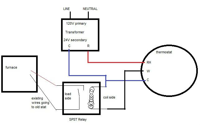
Solely a safety scenario. Same as case 2 except that the thermostat is not calling for heat and W and R are not connected via a relay. W is open circuit at the thermostat end. This case sets up a potential problem in that now the 24VAC from the secondary transformer is present inside the furnace on the 24VAC line and the coil of the heat relay or gas control valve is a connected to the other side of the furnace transformer and then returns to the thermostat via the W wire. If the W wire were connected to the C of the thermostat then a valid return path would exist and the back feeding of the furnace transformer is real and accordingly the primary would rise to 120VAC. But W is not connect to C. W is open circuit because the contacts of the heat relays are open. Without some current path from W to C at the thermostat, there is no current path to create the dangerous scenario. The attached diagram explains this fully. Conclusion no shock, no death, no blisters.


Even if you don’t believe me on case 2 and 3 you could simply put a sticker at the furnace shutoff switch that said something like. “This system is controlled by a remote WiFi thermostat with independent power source. When performing maintenance you must disconnect the power source at the thermostat in addition to switching off this disconnect point before performing any maintenance.” I tried not to use any big words so it should be understandable. This label is not needed but doesn’t hurt.

Same goes for your isolation relay. Not necessary but won’t hurt any. But when you add in fan control and AC compressor in addition to the heat that becomes three isolation relays and this quickly gets out of hand.

Here’s a number of web pages citing the 24VAC local transformer approach. I suppose you’ll hurl some insults to them as well.

http://tombuildsstuff.blogspot.com/2012/10/how-to-add-c-wire-to-thermostat.html
http://www.dslreports.com/forum/r29542718-HVAC-Installing-new-Honeywell-WiFi-thermostat-no-qcq-wire
http://diy.stackexchange.com/questi...nsformer-to-provide-a-c-wire-to-my-thermostat


This never started this as a preferred way to implement. I would always try to run a common wire back to the furnace. Depending on the home however, that can be near impossible after the fact. I was simply offering an alternative for folks unable to run the common line. I’ve shown why it will work and why it is safe by decomposing it to the component and current flow level. You’ve done neither and simply insulted me. Now who looks silly.
 

Attachments

  • Death Loop.jpg
    Death Loop.jpg
    127.9 KB · Views: 24

Rockhead261

Well-known member
Joined
Aug 28, 2013
Messages
1,911
Location
10509
I'm not sure if you're trolling at this point, so I'll just address the accusations of vulgarity, obscenity, and "potty mouth";

SCROTUM. noun, plural scrota [skroh-tuh] scrotums. Anatomy
1. the pouch of skin that contains the testes.

Seems to me your understanding of electricity is matched only by your command of the English language. :D

I await your video.
 

curiousB

Well-known member
Joined
Dec 15, 2011
Messages
143
Location
NW Chicago, IL
I'm not sure if you're trolling at this point, so I'll just address the accusations of vulgarity, obscenity, and "potty mouth";

SCROTUM. noun, plural scrota [skroh-tuh] scrotums. Anatomy
1. the pouch of skin that contains the testes.

Seems to me your understanding of electricity is matched only by your command of the English language. :D

I await your video.

hmmm as I expected, unable to argue with facts, reverts to insults and attacks to deflect.

Checkmate

noun

: a situation in chess in which a player loses the game because that player is in a position from which it cannot escape
 

Rockhead261

Well-known member
Joined
Aug 28, 2013
Messages
1,911
Location
10509
hmmm as I expected, unable to argue with facts, reverts to insults and attacks to deflect.

Fine, I'll give you a hint as to why you're wrong and hopefully you'll figure it out.

Didja notice those links you referenced only mention use of the unjumpered Rc terminal for the secondary transformer? Think about why that is and you'll have your answer as to why you CANNOT put two transformers under an R terminal.

I continue to await your video.
 

curiousB

Well-known member
Joined
Dec 15, 2011
Messages
143
Location
NW Chicago, IL
I just grew weary of your Neanderthal rants here. I see your pattern continues.

R vs Rc is not the eureka moment you seem to be hoping for. And I do mean hoping, as you seem to be just guessing for answers now. My arguments are sound and based on engineering principals, in stark contrast to your seat of the pants guessing. From the start I asked you to show the current path that caused the back feed of the furnace transformer. You haven’t been able to.

A person with the years of experience your claimed would understand the purpose of the two R types is when an AC unit has a separate 24VAC power source from the heating unit. Naturally you don’t want to connect these transformer primaries in parallel so the added option is to allow splitting them and the corresponding heat and cool relays.

In a home system with no AC you can take advantage of that capability to back feed the thermostat locally at the C and Rc lines. This way the R from the furnace is not tied to Rc at a low impedance level.

In the case of a furnace and AC unit this cannot be done as both lines (and corresponding relays) are used.

Of course none of this undermines my premise all along that there is no current path due to the now obvious floating C terminal of the thermostat. No current flow, no flux in core, no flux in core, no induced current in primary… Simple physics. Death and blistering avoided. Drama and knuckleheaded browbeating debunked.

As I stated before, Checkmate. I’m done with your juvenile behavior.
 
Last edited:

Rockhead261

Well-known member
Joined
Aug 28, 2013
Messages
1,911
Location
10509
As I stated before, Checkmate. I’m done with your juvenile behavior.

<sigh>

I sincerely apologize for your butthurt over my demearnor, but I as I freely admit - I am a cranky old-timer who has seen too much botched, half-azzed **** in my time to accept anything but a proper job. Sure, there are shortcuts. Some fail immediately, some take time, but they all eventually reveal themselves as poor design. Putting two transformer hot legs under an R terminal is a shortcut/workaround/juryrig and I have seen it hurt equipment and people.

Here's an excellent writeup with clear diagrams from an engineering firm. Note pages 7 and 8.

http://www.epatest.com/store/resources/images/misc/how-a-thermostat-operates.pdf

If you cannot accept this explanation and continue to support the improper method, that's fine. The OP seems to have taken my advice and is long gone. I'm done with this thread.
 
Last edited:
OP
R

RonRock

Well-known member
Joined
Oct 6, 2007
Messages
1,171
Location
Iowa, USA
I am still watching. I picked up a relay yesterday. Plan to get the thermostat wired in tomorrow. I figure I'll do it with a relay for now and keep an eye out for a deal on the proper primary control.
 
To avoid these ads, REGISTER NOW!
Top Bottom