To avoid these ads, REGISTER NOW!

Home Made Sharpening Jig for Bench Grinder

2oolhound

Well-known member
Joined
Dec 18, 2010
Messages
5,918
Location
BC Canada
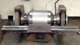
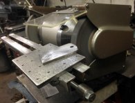
Hi guys, I restored a bench grinder but the guides to support the work were incomplete so I got to thinking how to make some that would make it possible to sharpen hand plane blades and similar things that I’ve always had trouble keeping a straight line on. I wound up making this full width track set up with a sliding sled.

attachment.php


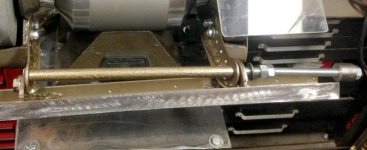
The track extends 5” past the wheels on both sides and tilts up and down so it’s deck angle aims from below center of the wheel, past center, to up over the top of the wheel so your angle of grind is adjustable. It swings upside down to get it out of the way too.

attachment.php


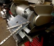
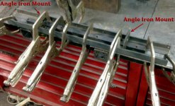
The sled is a 5”x7” plate with 3 - 1/2” square bars tacked onto the bottom so it contacts the track on the outer edges and the inner surface between the 2 rails. There is a 1 1/2” overhang on one edge of the sled so it can be turned around to reach close to the wheel when the track is tilted up. It is tapped for 1/4” hold down fasteners. The big hole in the center (2nd photo) is for a rotator plate I've added.

attachment.php


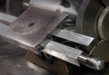
Here is a hand plane blade I put an edge on with this system. I didn’t grind out the old rounded corners at the shoulder of the edge, just the edge itself but I’m pretty happy with it so far. With the work clamped down you can slide the sled right off to dip the blade to cool it every 4 or 5 passes. I likely won’t be clamping too much to the sled, just hand holding it on there.

attachment.php


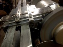
PS: by the way those 2 hold down bars with all the holes in them are just what was available and will be replaced. They aren’t needed most times. They are from some unknown machinist type devise so if anyone knows what they are please chime in.

In hind sight I should have made the parallel tracks to fit IN-BETWEEN the grinder mount arms so I could have welded a solid tube between the 2 mounts. The way it fits on the out-side of the arms allows for some distortion when tightening the tension to lock it’s angle. This tension is enough to bind the sled in the track. I have to keep it a little loose. Although it’s still quite usable I can’t lock it real tight so I’ll probably change that in the future.
 

Attachments

  • SharpeningJig_3261.jpg
    SharpeningJig_3261.jpg
    36.7 KB · Views: 344
  • SharpeningJig_3278.jpg
    SharpeningJig_3278.jpg
    57.1 KB · Views: 350
  • SharpeningJig_3287.jpg
    SharpeningJig_3287.jpg
    39.9 KB · Views: 343
  • SharpeningJig_3291.jpg
    SharpeningJig_3291.jpg
    35 KB · Views: 334
To avoid these ads, REGISTER NOW!
OP
2

2oolhound

Well-known member
Joined
Dec 18, 2010
Messages
5,918
Location
BC Canada
I really like it. :thumbup:

Would like to see more pics from the sides and underneath, showing how it adjusts, etc.

Thanks guys! Sorry for the delay, no internet at home. I use scavenged recycled materials I had on hand, farmer style welds (right over the powder coat) and seat of the pants engineering (design as you go) to do this project.

To keep the welding distortion to a minimum the 1” angle iron rails for the track were clamped to the bench. A piece of 1/2” bar stock (to be used for the guides on the bottom of the sled) was clamped between the angle iron rails for proper spacing. The short pieces of 2” x1/4” angle iron used for the 2 mounts were then clamped onto the rails so they would align with the grinder arms. I just tack welded here and there to try to lessen welding distortion.

attachment.php


After welding, the rails developed a hump (they curved up wards). I laid out a long 6” wide sanding belt on a long steel plate on my bench and rubbed the surface of the track (the joined rails) back and forth ad nauseam until the top of the track was within a few .001’s of flat. The other artifact from welding was the 2 rails splayed outwards at the ends past the mounts so I bent them back so the gap was 1/2” again. (think vise and hammer with spacers between the rails so they could be clamped in vise, then hammer the ends in).

attachment.php


New grinder arms were cut from 1/8” steel. Once rough cut they were clamped together with vise grips and drilled to match the 2 threaded mount holes on the grinder cast inner shrouds. This distance was repeated so I could vary the distance of the track as the grinder wheels wore down. Once the holes were drilled they were bolted together and the edges were ground to round the corners. I then welded a thin strip of 1/8” to the bottom edges perpendicular so it formed an angle iron shape so they wouldn’t flex. You can see them better 2 photos down.

attachment.php


In this shot (below) the track is turned upside down. You can see the left angle iron mount that join the 2 rails together. You can see how it was cut out in the center to allow the 1/2" square sled guides to pass through. It has a nut welded to it so a long piece of all-thread can pass through from the other side to tighten the track in position.

2 fiber washers are added for friction to help lock the track.

You can also see 2 bends in the grinder arm, one to the right and one back to the left. This arm was bent because the track was 1/32” further from the axis of the grinder shaft on this side and bending it out and back this tiny bit made the track parallel to the grinder shaft axis.

attachment.php


Here you can see the FATAL ERROR. You see the grinder arms have a spacer tube between them and the all-thread passing through. I just used a threaded 1 1/4” piece of round stock for a handle on the end to tighten the track into position. It is locked by a nut which allows the use of a wrench or ratchet but a big hand grip would be nicer. My phone camera has distorted the photo to make things look curved and out of square. The “fatal error” here is the fact that the track mounts have to squeeze in to hit the grinder arms and spacer tube to lock. This causes the track to flex and bind on the sled. Anyone making one of these should put the long spacer tube between the track mounts and make the track mounts fit inside the grinder arms so the grinder arms have to flex to lock the track. A nice thick spacer tube welded between the 2 track mounts would then allow the track to remain square. My other gripe is the all-thread flexes and I wish I’d threaded the end of a strong shaft or bolt instead or used a grade 8 all-thread.

attachment.php


I used a 5x7x3/8” piece of plate for the sled. It had a hole in the center. Notice how the right side over hangs the track by 1 1/4” while the left side is flush with the back of the track. With the track angle level or square to the grinder wheel you must rotate the sled 180' or the over hang will contact the wheel.

attachment.php


This is the bottom of the sled. These are the three 1/2” square guide bars that slide between the rails. The medium sized holes are counter sinks that go 1/2 way through, then the diameter reduces to 1/4” and the guide bars are plug welded through these holes to the top plate. I also tacked the ends to the plate. The small holes are the hold down holes for fixing things to the plate and the one large hole is that hole that was already in the piece of steel I used for the sled. The welding was done with the track rails clamped in between to help keep things in position.

attachment.php
 

Attachments

  • SharpeningJig_3304.jpg
    SharpeningJig_3304.jpg
    68.6 KB · Views: 101
  • SharpeningJig_3265.jpg
    SharpeningJig_3265.jpg
    37.2 KB · Views: 101
  • SharpeningJig_3315.jpg
    SharpeningJig_3315.jpg
    33.2 KB · Views: 101
  • SharpeningJig_3314.jpg
    SharpeningJig_3314.jpg
    63 KB · Views: 100
  • SharpeningJig_3249.jpg
    SharpeningJig_3249.jpg
    51 KB · Views: 100
  • SharpeningJig_3250.jpg
    SharpeningJig_3250.jpg
    26.7 KB · Views: 100
  • SharpeningJig_3247.jpg
    SharpeningJig_3247.jpg
    52.3 KB · Views: 103
OP
2

2oolhound

Well-known member
Joined
Dec 18, 2010
Messages
5,918
Location
BC Canada
Regardless, the plug welds caused the guide bars to swell around the welds and I had to file and then polish the sides of the guide bars with emery cloth to make them flat again so they would fit and slide freely inside the track rails.

attachment.php


attachment.php


That’s about as far as one has to go with this but that hole in the sled plate was annoying so I fashioned a rotating top plate for grinding arcs.

attachment.php


The rough hole was reamed out to round and make it a snug fit to the pin. The pin was frozen and the top plate heated so the pin could be pressed into the top plate creating an interference fit. To make this arc guide more versatile the main plate should have a slot machined perpendicular to it’s sideways movement then an intermediate plate with a hole in it could slide up and down and a third top plate could rotate giving you capabilities to grind many arc angles.

attachment.php


All my grinders are on bayonet or receiver hitch mounts so this one is on a dual mount. I made a shelf between the receiver tubes where I keep a box to hold accessories under the grinder.

attachment.php
 

Attachments

  • SharpeningJig_3259.jpg
    SharpeningJig_3259.jpg
    55 KB · Views: 94
  • SharpeningJig_3254.jpg
    SharpeningJig_3254.jpg
    61.6 KB · Views: 94
  • SharpeningJig_3325.jpg
    SharpeningJig_3325.jpg
    45.2 KB · Views: 94
  • SharpeningJig_3331.jpg
    SharpeningJig_3331.jpg
    52.7 KB · Views: 94
  • SharpeningJig_3338.jpg
    SharpeningJig_3338.jpg
    58.8 KB · Views: 94
To avoid these ads, REGISTER NOW!
Top Bottom