To avoid these ads, REGISTER NOW!

When or If Bushings Are Needed on PVC Conduit?

larry4406

Well-known member
Joined
Jan 27, 2006
Messages
19,299
Location
Northern Virginia
Before I pull any wire, I figure I should ask the subject question.

My project has 1", 2", and 3" PVC Schedule 40 conduits. I have male terminal adapters at all conduit ends - panel box and PVC junction box.

This thread indicates that bushings are needed anytime that #4 or larger wire is used.
https://forums.mikeholt.com/showthread.php?t=150908

This thread indicates that bushings are not needed when PVC terminal adapters are used.
https://diy.stackexchange.com/quest...need-a-termination-bushing-at-a-service-panel

My barn feeder will most likely be 2/0. The lighting and outlet circuits I have not yet sized but I am thinking the outlet circuit will be #8 while the lighting maybe #10. The wire sizing discussion for my project is here https://www.garagejournal.com/forum/showthread.php?t=426420

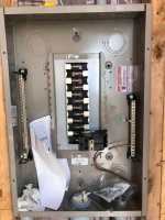
For grins, I opened up the septic sub panel at my house (picture attached). It is connected with PVC conduit and flexible liquid-tite conduit. The CDR 6 AWG wire enters on the left and it is bushed while the wires to the pumps and controller exit on the right and are not bushed (I don't know their wire sizes). This panel was installed by an electrician prior to our purchase when the seller installed a new septic system. So I don't think I learned anything from this example.
 

Attachments

  • Septic Sub-Panel.jpg
    Septic Sub-Panel.jpg
    74.4 KB · Views: 139
To avoid these ads, REGISTER NOW!

Norcal

Well-known member
Joined
Mar 16, 2008
Messages
13,758
While I did not open either link, a bushing is required no matter what type of conduit is used if the conductors are 4 AWG or larger.
 
OP
L

larry4406

Well-known member
Joined
Jan 27, 2006
Messages
19,299
Location
Northern Virginia
Why are you using #8 for outlets and #10 for lighting?

Outlets on a 20A circuit at 140'?

Lighting on a 3-way circuit at 270'?

My understanding is that at the fixture pigtails are used to connect the outlet or lighting. Will use 12g for the 20A outlets and 14g for the lighting fixtures. Open for suggestions on how this is normally addressed. Has to be a common condition.

Wire sizing seems to be a black art. The calculators out there all give different results. Who has a link to a correct one?
 
Last edited:

sberry

Banned
Joined
Jun 18, 2005
Messages
35,747
Location
Brethren, Michigan
Why do you need 20A? There is an assumption that every circuit with a 20A breaker has that load. I disn't read the other thread word for word but saw something about 300 watts of lights on a circuit but calculating the voltage drop at 15A.
Real loads are different, most max about 13 and some tolerate a little drop without issue. You could run a wire feeder at 150 ft 10. Use 15A outlets anyway,,, very few places need 20 and most are for janitorial to keep the cleaning lady from plugging in to the computer and science lab, forces them on to dedicated circuits.
 

alfredeneuman

Well-known member
Joined
Mar 3, 2011
Messages
4,581
Location
Fullerton, CA
The Holt forum is a group of professional electricians.
The DIY stack exchange is just what it says it is....A DIY site.

Which one are you going to trust for information?:lol_hitti
 
OP
L

larry4406

Well-known member
Joined
Jan 27, 2006
Messages
19,299
Location
Northern Virginia
The Holt forum is a group of professional electricians.
The DIY stack exchange is just what it says it is....A DIY site.

Which one are you going to trust for information?:lol_hitti

The Holt Forum. I also respect the sparkies here. I also like confirming from several sources when I know I am not an expert on the subject at hand.
 

mm08822

Well-known member
Joined
Jan 13, 2012
Messages
5,957
Location
NJ
There are a few different inputs required to do VD calcs. Not sure every website takes those details into account.
Temperature inputs are typically used for conductors exposed to elevated temps. Not a concern for buried cables/conductors – keep it at the default.

Southwire app is reliable. (It does however confuse people with the conductor sizing @ 60C ampacity rating below 100a b/c of nm-b ratings, but the voltage drop calculated per wire size and the size recommendation is correct. It really needs to have an insulation selection input to eliminate this confusion. – This is not a concern for your feeder.)

The CH2100 has max wire range to 1/0. Consider 1/0 CU @ the house jb to panel. This adds some cost and a set of splices.
There is also CH2125 & CH 2150 good for up to 3/0 conductor size. I would use the CH2125 with 2/0 AL XHHW. Put 100a sub panels in each detached location with main cb’s. Check if there are buss stub max loading limitiations.

Your 3 way circuit for lighting at both locations controlled from 3 locations has about 1200’ of total circuit length. For 120vac @ 1.5A and 3%vd, you will need #10 CU. I would suggest using a 2 or 3 pole 120vac coil relay to drive the loads at each location. This way the 3 way ckt is only carrying a super low current even if your needs change and you want to light up the world.
You could shove a 2pole ice cube relay into a 4-11/16” x 2-1/8” box at each location.

Wireless is an option otherwise.
 

wyliesdiesels

Well-known member
Joined
Aug 14, 2012
Messages
20,022
Location
Modesto, CA
Outlets on a 20A circuit at 140'?

Lighting on a 3-way circuit at 270'?

My understanding is that at the fixture pigtails are used to connect the outlet or lighting. Will use 12g for the 20A outlets and 14g for the lighting fixtures. Open for suggestions on how this is normally addressed. Has to be a common condition.

Wire sizing seems to be a black art. The calculators out there all give different results. Who has a link to a correct one?

as said above, the best way to do calcs is by doing the math yourself...
 
OP
L

larry4406

Well-known member
Joined
Jan 27, 2006
Messages
19,299
Location
Northern Virginia
There are a few different inputs required to do VD calcs. Not sure every website takes those details into account.
Temperature inputs are typically used for conductors exposed to elevated temps. Not a concern for buried cables/conductors – keep it at the default.

Southwire app is reliable. (It does however confuse people with the conductor sizing @ 60C ampacity rating below 100a b/c of nm-b ratings, but the voltage drop calculated per wire size and the size recommendation is correct. It really needs to have an insulation selection input to eliminate this confusion. – This is not a concern for your feeder.)

The CH2100 has max wire range to 1/0. Consider 1/0 CU @ the house jb to panel. This adds some cost and a set of splices.
There is also CH2125 & CH 2150 good for up to 3/0 conductor size.
I would use the CH2125 with 2/0 AL XHHW. Put 100a sub panels in each detached location with main cb’s. Check if there are buss stub max loading limitiations.

Your 3 way circuit for lighting at both locations controlled from 3 locations has about 1200’ of total circuit length. For 120vac @ 1.5A and 3%vd, you will need #10 CU. I would suggest using a 2 or 3 pole 120vac coil relay to drive the loads at each location. This way the 3 way ckt is only carrying a super low current even if your needs change and you want to light up the world.
You could shove a 2pole ice cube relay into a 4-11/16” x 2-1/8” box at each location.

Wireless is an option otherwise.

Thank you for your input! I thought the 2/0 would have excessive VD for 100A at 270'? At least that is what my other thread seems to be concluding.

How do I check for buss stab max loading limitations? This means nothing to me.

How would I set up the ice cube relays for the lighting circuit? Wire the lighting circuit normally like a 3-way or 4-way fed from the barn but instead of a light (load) connection, connect the circuit to a local relay and energize the other side of the relay from the structure in question? What wiring would you use? I have one light at the barn source, two lights that are in the yard to illuminate pathways (one at 75' from the barn and the other at 140' from the barn so no local power at their locations so these would have to be feed from the barn), while the future garage would have its own panel.

I was contemplating using the attached 3-way wiring diagram concept which would ultimately change to a 4-way. Lights are dead ended off the first powered switch while the switches daisy chain. The barn light and 2 intermediate lights would need to be feed from the barn. I would include a neutral along for the ride in each switch box as apparently that is required now.
 

Attachments

  • 3-way-switch-diagram-8.pdf
    78.5 KB · Views: 7
To avoid these ads, REGISTER NOW!

mm08822

Well-known member
Joined
Jan 13, 2012
Messages
5,957
Location
NJ
Thank you for your input! I thought the 2/0 would have excessive VD for 100A at 270'? At least that is what my other thread seems to be concluding.

How do I check for buss stab max loading limitations? This means nothing to me.

How would I set up the ice cube relays for the lighting circuit? Wire the lighting circuit normally like a 3-way or 4-way fed from the barn but instead of a light (load) connection, connect the circuit to a local relay and energize the other side of the relay from the structure in question? What wiring would you use? I have one light at the barn source, two lights that are in the yard to illuminate pathways (one at 75' from the barn and the other at 140' from the barn so no local power at their locations so these would have to be feed from the barn), while the future garage would have its own panel.

I was contemplating using the attached 3-way wiring diagram concept which would ultimately change to a 4-way. Lights are dead ended off the first powered switch while the switches daisy chain. The barn light and 2 intermediate lights would need to be feed from the barn. I would include a neutral along for the ride in each switch box as apparently that is required now.
……

So here's where the problems start.....not sure if you will ever load the feeder to a full 100A. Even if yes, how much does barn draw and how much for garage?
What are the loads? Is this purely speculation and 100 is just a nice round number? The higher the load at the barn, the greater the vd due to distance.
I'm guessing you won't ever hit 100a.

CH breakers only go up to 1/0 wire size until you get to 125A (CH2125 = 2/0, CH2150= 3/0 max). The 150a cb has a footnote that it is only for 400a/600a rated panels. Seems to be 125a frame size, so buss stab rating must be limiting it. So you're left with 125A.

Here is an example for Siemens panel indicating buss stab max load. See if you can find the equivalent info in your panel.

Siemens buss stab example.JPG

Then we get to the panels. 100A CH panel breaker lugs only go up to 1/0. 125a and 200a go to 300mcm. So pick a main cb panel bigger than 100a to get a larger wire range on the main cb.
You could transition to copper and splice it onto the Al to fit a smaller cb, but that just adds a bunch garbage into the circuit. Either way you have to spend a few extra $$ to make the pieces fit together. Do it the cleanest way - no splices just to fit cb's.

For the lighting - why feed everything out of the barn and then come all the way back to the house for an s3?? This just adds more vd needlessly.
Feed the ckt from the house panel and go out to the barn, pedestal, fence post and future garage. With the fence post and pedestal lights, they partially screw up my idea with the relays. So now you need to know the lighting loads at these 2 locations to properly calculate the vd of this 3 way ckt. (in future becomes 4 way - even more vd.)
You want to control the same lights from 3 separate buildings. 2 buildings will have to have "a second feed" to them. No problem - just mark the switches with a note for the next guy. You're not the 1st to do this.
 

ard

Well-known member
Joined
Feb 16, 2015
Messages
4,391
Location
Sierra Foothills... California
How do I check for buss stab max loading limitations? This means nothing to me..

When you click a circuit breaker into the panel, the thing it slides onto is the 'buss". When a breaker slides on (versus being bolted to the buss) it is a 'stab; mount. (you likely recall the loathed 'back stabs'...)


You read the specs for whatever panel you have, it will list a max breaker amperage.
 
OP
L

larry4406

Well-known member
Joined
Jan 27, 2006
Messages
19,299
Location
Northern Virginia
……

So here's where the problems start.....not sure if you will ever load the feeder to a full 100A. Even if yes, how much does barn draw and how much for garage?
What are the loads? Is this purely speculation and 100 is just a nice round number? The higher the load at the barn, the greater the vd due to distance.
I'm guessing you won't ever hit 100a.

CH breakers only go up to 1/0 wire size until you get to 125A (CH2125 = 2/0, CH2150= 3/0 max). The 150a cb has a footnote that it is only for 400a/600a rated panels. Seems to be 125a frame size, so buss stab rating must be limiting it. So you're left with 125A.

Here is an example for Siemens panel indicating buss stab max load. See if you can find the equivalent info in your panel.

Siemens buss stab example.JPG

Then we get to the panels. 100A CH panel breaker lugs only go up to 1/0. 125a and 200a go to 300mcm. So pick a main cb panel bigger than 100a to get a larger wire range on the main cb.
You could transition to copper and splice it onto the Al to fit a smaller cb, but that just adds a bunch garbage into the circuit. Either way you have to spend a few extra $$ to make the pieces fit together. Do it the cleanest way - no splices just to fit cb's.

For the lighting - why feed everything out of the barn and then come all the way back to the house for an s3?? This just adds more vd needlessly.
Feed the ckt from the house panel and go out to the barn, pedestal, fence post and future garage. With the fence post and pedestal lights, they partially screw up my idea with the relays. So now you need to know the lighting loads at these 2 locations to properly calculate the vd of this 3 way ckt. (in future becomes 4 way - even more vd.)
You want to control the same lights from 3 separate buildings. 2 buildings will have to have "a second feed" to them. No problem - just mark the switches with a note for the next guy. You're not the 1st to do this.

Again, thank you for your response!

You are correct. I have not done any load calc, just picked a nice round number. I am a one man band so I won't be in the garage and barn at same time but who knows, someone might one day. Baldor 7.5HP compressor, occasional 240V mig welder, lighting, maybe AC or electric space heat. I agree highly unlikely I would ever hit a 100A ceiling.

My work will be inspected. I just don't want to get challenged by an inspector on wrong cable and breaker sizes due to voltage drop over the full run. I always try to do the right thing in whatever I do.

My house panel is a Cutler Hammer CH40KKM200. There is a label inside that says "Branch fingers rated 140A max." If I understand you correctly, then I could use a 125A breaker here because it would fit the 2/0 AL and thus avoid the copper transition clap trap (although I could keep it at 100A but would need to transition to copper due to its 1/0 size limit).

The barn panel is already installed. It is an Eaton CH22B100V. The product literature says 100A rating (I have not had a chance to open the cover, pouring rain outside). I suspect I have no choice but to transition 2/0 Al to copper here to fit the 100A breaker. The panel has room for these transitions (assuming the splices are ok to be in the panel). What size copper do I use? I assume I use inline splices and tape them appropriately or use Polaris types. Likely will need to move the 100A main breaker to upper left to aid in cable management.

Regarding the lighting circuit, the only reason I was proposing to feed it from the barn was the prohibition against "second feed" to a structure. IF labeling will suffice than that makes things easier. Will labeling pass inspection?

Thank you again!
 

Attachments

  • Barn Panel Eaton CH22B100V.jpg
    Barn Panel Eaton CH22B100V.jpg
    117.3 KB · Views: 21

m32825

Well-known member
Joined
Jul 26, 2015
Messages
1,009
Location
Central FL
"I just don't want to get challenged by an inspector on wrong cable and breaker sizes due to voltage drop..."

The inspector (and NEC) is focused on safety issues, voltage drop is a design issue.
 

Bert_

Well-known member
Joined
Dec 24, 2016
Messages
9,745
Location
NW Iowa
Those breakers may fit 2/0 aluminum as long as it's compact. Most aluminum these days is compact.
 

mm08822

Well-known member
Joined
Jan 13, 2012
Messages
5,957
Location
NJ
Those breakers may fit 2/0 aluminum as long as it's compact. Most aluminum these days is compact.

That’s a good catch Bert.
I compared the diameters of Southwire Simpull 1/0 XHHW CU (circular stranding) to that of Southwire Simpull 2/0 XHHW AL (compact stranding) and they are very close in diameter.

2/0 AL = 490 mills – 2x 55mils = 380 mills
1/0 CU = 477 mills – 2 x 55 mills = 368 mills

SW_Simpull_AL_vs_CU.JPG

Technically, 2/0 ≠ 1/0 as per the specified product listing/usage range. I would not worry about it. If it fits, use it.
 
Last edited:

mm08822

Well-known member
Joined
Jan 13, 2012
Messages
5,957
Location
NJ
Again, thank you for your response!

You are correct. I have not done any load calc, just picked a nice round number. I am a one man band so I won't be in the garage and barn at same time but who knows, someone might one day. Baldor 7.5HP compressor, occasional 240V mig welder, lighting, maybe AC or electric space heat. I agree highly unlikely I would ever hit a 100A ceiling.

My work will be inspected. I just don't want to get challenged by an inspector on wrong cable and breaker sizes due to voltage drop over the full run. I always try to do the right thing in whatever I do.

My house panel is a Cutler Hammer CH40KKM200. There is a label inside that says "Branch fingers rated 140A max." If I understand you correctly, then I could use a 125A breaker here because it would fit the 2/0 AL and thus avoid the copper transition clap trap (although I could keep it at 100A but would need to transition to copper due to its 1/0 size limit).

The barn panel is already installed. It is an Eaton CH22B100V. The product literature says 100A rating (I have not had a chance to open the cover, pouring rain outside). I suspect I have no choice but to transition 2/0 Al to copper here to fit the 100A breaker. The panel has room for these transitions (assuming the splices are ok to be in the panel). What size copper do I use? I assume I use inline splices and tape them appropriately or use Polaris types. Likely will need to move the 100A main breaker to upper left to aid in cable management.

Regarding the lighting circuit, the only reason I was proposing to feed it from the barn was the prohibition against "second feed" to a structure. IF labeling will suffice than that makes things easier. Will labeling pass inspection?

Thank you again!

I doubt you will get harassed for vd as it is not currently enforced in NEC. It is for you and the life of your equipment.

For possible relief to the wire size & cb wire range.....checkout what Bert suggested.


You should ask your inspector about this. You will have 3 buildings, each with it’s own switch to control the same lights in between and at each building exterior. There is a conflict no matter what you do in this situation. See what floats his boat.

Worst case – put the switch and light on the building exterior and it then never enters the bldg. Possible “way around” requirement.

Really worst case – do it after inspection.
 

wyliesdiesels

Well-known member
Joined
Aug 14, 2012
Messages
20,022
Location
Modesto, CA
Have you checked with your PoCo to see if the 7.5HP motor is ok to use? Many PoCos have limits on HP ratings.
 
Last edited:

mm08822

Well-known member
Joined
Jan 13, 2012
Messages
5,957
Location
NJ
Again, thank you for your response!

You are correct. I have not done any load calc, just picked a nice round number. I am a one man band so I won't be in the garage and barn at same time but who knows, someone might one day. Baldor 7.5HP compressor, occasional 240V mig welder, lighting, maybe AC or electric space heat. I agree highly unlikely I would ever hit a 100A ceiling.

My work will be inspected. I just don't want to get challenged by an inspector on wrong cable and breaker sizes due to voltage drop over the full run. I always try to do the right thing in whatever I do.

My house panel is a Cutler Hammer CH40KKM200. There is a label inside that says "Branch fingers rated 140A max." If I understand you correctly, then I could use a 125A breaker here because it would fit the 2/0 AL and thus avoid the copper transition clap trap (although I could keep it at 100A but would need to transition to copper due to its 1/0 size limit).

The barn panel is already installed. It is an Eaton CH22B100V. The product literature says 100A rating (I have not had a chance to open the cover, pouring rain outside). I suspect I have no choice but to transition 2/0 Al to copper here to fit the 100A breaker. The panel has room for these transitions (assuming the splices are ok to be in the panel). What size copper do I use? I assume I use inline splices and tape them appropriately or use Polaris types. Likely will need to move the 100A main breaker to upper left to aid in cable management.

Regarding the lighting circuit, the only reason I was proposing to feed it from the barn was the prohibition against "second feed" to a structure. IF labeling will suffice than that makes things easier. Will labeling pass inspection?

Thank you again!

You could use a total of 140a on that stab. E.g. - 125a cb (left side) + 15a cb (right side)......or 100a + 40a, etc....
 
OP
L

larry4406

Well-known member
Joined
Jan 27, 2006
Messages
19,299
Location
Northern Virginia
Have you checked with your PoCo to see if the 7.5HP motor is ok to use? Many PoCos have limits on HP ratings.

No I did not. Never occurred to me. Surely if it was not consumer rated it would be restricted from sale? ;)

I guess I am a bad guy. :) I will plead ignorant.

It's been here at the house now for 5 years and no one has come to complain. I use it quite a bit.

What's interesting that it's here in the attached garage now (200A service) but the lights don't flicker or dim when it kicks on. We have a transformer at the driveway pole feeding the house maybe 100' away so I am sure that helps. We are also rural so maybe the main line is oversize.

Hopefully me relocating it to the barn doesn't cause issues. Would hate to move the beast twice.

Picture of Baldor motor nameplate attached.
 

Attachments

  • Baldor Compressor Motor.jpg
    Baldor Compressor Motor.jpg
    62 KB · Views: 17
OP
L

larry4406

Well-known member
Joined
Jan 27, 2006
Messages
19,299
Location
Northern Virginia
You could use a total of 140a on that stab. E.g. - 125a cb (left side) + 15a cb (right side)......or 100a + 40a, etc....

Thank you yet again! Getting down to the necessary essential details!

I think I will have to move some circuits around to achieve this.

At present the 50A range is opposite where I was thinking to place the barn breaker. I could move the proposed barn breaker location downward and move some others upward, then there would be two 15A breakers opposite the 125A; would this suffice? If not then I think I will need to bug the 2/0 AL to 1/0 copper(?) so that a 100A breaker will work.
 

wyliesdiesels

Well-known member
Joined
Aug 14, 2012
Messages
20,022
Location
Modesto, CA
if you have your own transformer and the primary lines are large then it may very well not be an issue.

i have seen it an issue before where someone flipped on their 7.5hp or 10hp motor and it caused major voltage sag in the neighborhood.
 
OP
L

larry4406

Well-known member
Joined
Jan 27, 2006
Messages
19,299
Location
Northern Virginia
if you have your own transformer and the primary lines are large then it may very well not be an issue.

i have seen it an issue before where someone flipped on their 7.5hp or 10hp motor and it caused major voltage sag in the neighborhood.

Interesting.

My next door neighbor has a huge house with either 600A or 1000A service, CT cabinet and all. He also has 2 detached garages each with their own meters (not sure panel size). He is a ********* car guy and he and is son are running TIG, plasma, compressors, etc near constant. I also don't know if we are loop feed or dead ended on our street (ie - I don't know if I am upstream or downstream of my power user neighbor).
 
To avoid these ads, REGISTER NOW!
Top Bottom