To avoid these ads, REGISTER NOW!

CM pre-Block Grinder 115.19500 restore, ver. 2

torqueman2002

Well-known member
Joined
Jun 3, 2009
Messages
6,138
Location
SE Michigan
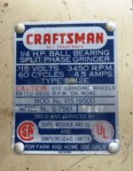
Member dogzbody1 kindly sent me his problem pre-Block 1/4-HP, m-115.19500 grinder for the mere cost of shipping. :bowdown:

I optimistically told him I'd look at it in a day or two. That was over 6 months ago!

Anyway, after doing some pre-spring cleaning in the garage-shop, I could finally see the top of the work bench a couple of nights ago. Feeling good about that no-small task, I headed into the house at about 10:30 PM.

Then it happened. I caught my boot on the corner of the box with the Block in it. Oh well, time to take it out of the box and just look at it. Yea, right.

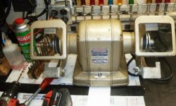
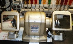
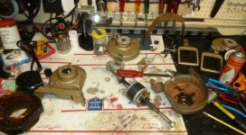
The next thing I knew, this is how my clean bench top looked.
attachment.php


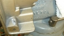
Sorry, no before pictures owing to the lateness of the hour and laziness of the Blockhead. Suffice it to say, this is a sweet little, if not heavy (CI) pre-Block!

It may just get a good scrubbing with Simple Green, instead of a lick of paint.

Also, I didn't run it because I vaguely recall dogzbody1 posting it may have stalled and smoked on power-up, which can be a fatal sign. I later confirmed this, when I found his original post. https://www.garagejournal.com/forum/showpost.php?p=6737761&postcount=805
Update: I heard from dogz: 'It smoked at start and did spin after I helped it, ...'


Dogz - congratulations! You definitely saved this guy by giving it that spin! That's grinder CPR.

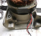
The early Blocks (pre-Blocks, ++ ?) do not use a start-up relay. Rather, they use a mechanical centrifugal-switch (CS).

Levers on the arbor shaft attached to weights press a low-friction, non-conductive sliding collar that presses against a plate with a set of electrical contacts, which is mounted to the RH end frame. At start, the collar is pressing on the CS plate, closing the contacts and connecting the start winding. Full description, here. --> https://en.wikipedia.org/wiki/Centrifugal_switch

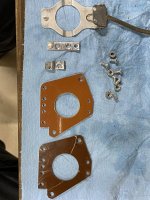
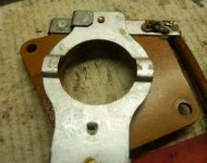
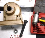
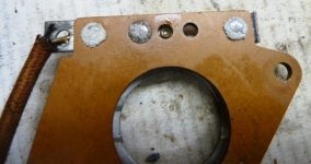
Centrifugal-switch (CS), removed from RH end frame. The brown mounting plate is quite fragile and care needs to be taken when disassembling.
attachment.php


If the RH bearing is stuck to the arbor and the arbor is removed with the CS still attached to the RH end frame, the CS can be damaged/destroyed.

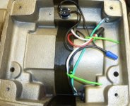
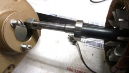
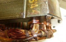
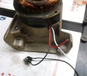
In this case the bearing stayed in the RH end frame, so removing the CS first was not necessary. I cut the white wire from the start-up winding to the CS. The other white wire from the CS goes to a splice with the power cord neutral (white) and the run winding (red) wires, under the grinder cover.

After removing the LH end frame, where the bearing stayed on the LH arbor shaft, I was able to maneuver the winding assembly enough to remove the 2 mounting screws holding the CS to the RH end frame, so the CS was free to be removed with arbor & winding assemblies. As mentioned, it turned out the bearing stayed in the RH end frame.

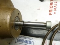
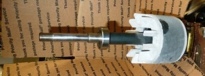
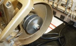
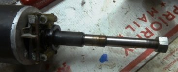
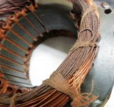
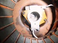
Here is the arbor assembly, RH view, showing the mechanical weights and lever of the CS.
attachment.php


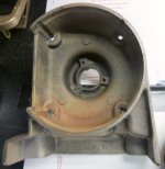
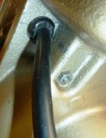
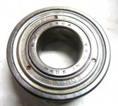
RH end frame with bearing. Dark looking wet spots are Kroil penetrating oil.
attachment.php


LH bearing/arbor.
attachment.php


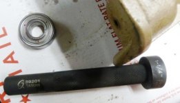
Detail of LH bearing mounting hole in the end frame.
attachment.php


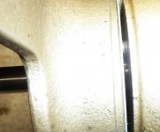
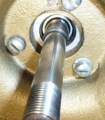
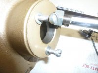
Detail of RH bearing mounting hole in the end frame.
attachment.php


Note the ridge on the inside of the bore. This keeps the bearing in the RH end frame when the arbor assembly is removed. Greatly simplifying disassembly. This must have been a manufacturing revision, earlier pre-Blocks did not have this, IIRC.

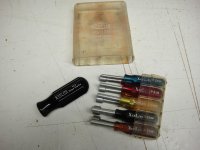
I haven't detailed the LH bearing removal from the arbor shaft. It has been posted previously. I will look for the link and post it here. https://www.garagejournal.com/forum/showthread.php?p=5722705#post5722705
 

Attachments

  • Fi P1120963.JPG
    Fi P1120963.JPG
    91.3 KB · Views: 669
  • Fi P1120964.JPG
    Fi P1120964.JPG
    111.7 KB · Views: 655
  • Fi P1120968.JPG
    Fi P1120968.JPG
    71.5 KB · Views: 648
  • Fi P1120969.JPG
    Fi P1120969.JPG
    108.7 KB · Views: 647
  • Fi P1120987.JPG
    Fi P1120987.JPG
    97.4 KB · Views: 642
  • Fi P1120989.JPG
    Fi P1120989.JPG
    48 KB · Views: 636
  • Fi P1120981.JPG
    Fi P1120981.JPG
    47.2 KB · Views: 633
Last edited:
To avoid these ads, REGISTER NOW!
OP
T

torqueman2002

Well-known member
Joined
Jun 3, 2009
Messages
6,138
Location
SE Michigan
Once the arbor and winding assemblies are removed, the RH bearing is removed from the inside of the end frame using a Sunex Tools bearing/seal driver tool.

I first used the 1.25" (31.75mm) to remove, but to temporarily re-install I noticed the 1.375" (34.925mm) was a better match to the OD.
attachment.php

attachment.php


ND 3202
15 mm Bore ID,
35 mm OD,
11 mm Width
attachment.php


ND 3202 cross references to: NTN Bearing 6202ZZ (eBay sourced, cheaper and faster than Amazon!?)

Single Row Deep Groove Radial Ball Bearing, Normal Clearance, Steel Cage, 15 mm Bore ID, 35 mm OD, 11 mm Width, Double Shielded.

A 2RU suffix for 2 non-contact rubber seals. A 2RS suffix would be for 2 rubber contact seals and they will generate more heat, probably not a real issue for occasional farm and home use. :thumbup:

Close look at the windings. Thin wires are start-up windings and cannot withstand full run current; thus the need for the CS or relay that open the start-up circuit at about 75% of full speed.
attachment.php


Heavy gauge wire of run winding, and a major reason for the robustness of the 'Block' grinder!
attachment.php


View of winding splice with aged and brittle cloth covered wire.
attachment.php


Start-up winding connection.
attachment.php


The cloth covered wires are so stiff and brittle, I don't trust them. They will be cut as short as possible and new wire soldered and heat shrink will be installed.
 

Attachments

  • Fi P1120980.JPG
    Fi P1120980.JPG
    115.5 KB · Views: 618
  • Fi P1120979.JPG
    Fi P1120979.JPG
    88.1 KB · Views: 612
  • Fi P1120978.JPG
    Fi P1120978.JPG
    111.8 KB · Views: 609
  • Fi P1120974.JPG
    Fi P1120974.JPG
    117 KB · Views: 609
  • Fi P1120975.JPG
    Fi P1120975.JPG
    137.9 KB · Views: 611
  • Fi P1120976.JPG
    Fi P1120976.JPG
    103.5 KB · Views: 606
  • Fi P1120977.JPG
    Fi P1120977.JPG
    90.5 KB · Views: 608
Last edited:
OP
T

torqueman2002

Well-known member
Joined
Jun 3, 2009
Messages
6,138
Location
SE Michigan
Views of the centrifugal switch (CS).

This side faces the arbor-rotor/spring, weight, sliding collar assembly.
attachment.php


Back side of CS. Note the white fuzz on the rivets.
attachment.php


Side view of CS, showing the spring that holds the contacts OPEN when the sliding collar is retracted by the weights and levers attached to the arbor. Again, notice the white fuzz.
attachment.php


The CS contact points were free of the white fuzz, and measured 0.0 Ohms closed.

The power switch measured 0.1 Ohms when closed/On.

The CS was given a good cleaning with alcohol to remove the white fuzz. Then the CS and power switch were given a spritz or 2 of CAIG DeOxit Cleaning Solution Spray and operated several times and given another couple of spritzes.

The mechanical part of the CS attached to the arbor was cleaned with alcohol and given a light amount of WD40. The springs were removed for better access.
attachment.php


The original wires were removed from the CS, power switch, and cut as short as possible from the windings. New flexible wire was soldered and heat shrink was used on the splices.
attachment.php


CS with new wires installed in RH end frame.
attachment.php


Power switch and winding with new wires installed. Getting ready for testing.
attachment.php
 

Attachments

  • Fi P1120967.JPG
    Fi P1120967.JPG
    89.8 KB · Views: 584
  • Fi P1120965.JPG
    Fi P1120965.JPG
    92 KB · Views: 588
  • Fi P1120964.JPG
    Fi P1120964.JPG
    111.7 KB · Views: 587
  • Fi P1120982.JPG
    Fi P1120982.JPG
    109.3 KB · Views: 584
  • Fi P1120983.JPG
    Fi P1120983.JPG
    115.1 KB · Views: 586
  • Fi P1120984.JPG
    Fi P1120984.JPG
    99.2 KB · Views: 586
  • Fi P1120986.JPG
    Fi P1120986.JPG
    61 KB · Views: 586
Last edited:
OP
T

torqueman2002

Well-known member
Joined
Jun 3, 2009
Messages
6,138
Location
SE Michigan
View of the wire/splice from the start winding to the centrifugal switch.
attachment.php


View of LH end bell. I believe the rust is probably due to storage in a humid location. This does not look like Block grinders that have heavy corrosion caused by standing water.
attachment.php


RH end bell, prior to bearing removal. As previously mentioned, due to the machined inner lip in the bearing mounting bore, the bearing should be driven out from the inside.
attachment.php


The Block is assembled with a grounded test power cord and waiting for a power ON test.
attachment.php


It spun up, first try! :thumbup:
attachment.php


Wiring diagram, with resistance specs and bearing information.
attachment.php


Very nice machine tag for a 67 year old! This Block is in fine shape and will grind and wire wheel again, soon!
attachment.php


I will post more pictures when the new bearings and power cord arrive and are installed.

Thanks for viewing.:)
 

Attachments

  • Fi P1120971.JPG
    Fi P1120971.JPG
    132.3 KB · Views: 561
  • Fi P1120995 a.jpg
    Fi P1120995 a.jpg
    147.8 KB · Views: 577
  • Fi P1120993.JPG
    Fi P1120993.JPG
    113.8 KB · Views: 567
  • Fi P1120994.JPG
    Fi P1120994.JPG
    120.3 KB · Views: 574
  • Fi P1120973.JPG
    Fi P1120973.JPG
    107.2 KB · Views: 570
  • Fi P1120972.JPG
    Fi P1120972.JPG
    103.2 KB · Views: 565
  • Fi P1120985.JPG
    Fi P1120985.JPG
    102 KB · Views: 571
Last edited:
OP
T

torqueman2002

Well-known member
Joined
Jun 3, 2009
Messages
6,138
Location
SE Michigan
March 31, 2020

It's back together and running just like it should.
attachment.php


For details please go down to post #32, March 31, 2020.
:thumbup:
 

Attachments

  • Fi P1130046.jpg
    Fi P1130046.jpg
    46.5 KB · Views: 371
Last edited:

lafester

Well-known member
Joined
Mar 1, 2017
Messages
2,191
Location
Northern CO
It lives! Looks like you have a good start on that one.
I used to hate the gold Craftsman but it is starting to grow on me, at least in small doses like on a grinder.
 

Old Radar

Well-known member
Joined
Apr 17, 2019
Messages
2,754
Location
San Antonio, TX
Great documentation TM! I've got a 1948 Dunlap 1/4hp grinder that I disassembled to change the bearings and broke the fragile brown mounting plate of the centrifugal-switch. That was before I joined GJ or knew what to expect when I cracked it open. It was kinda like that time when I was 12 and pulled out the cylinder of my closet lock and all the pins shot all over the room--instantaneously self-critiquing. And while I recovered from the lock fiasco after about three hours of work, I still haven't fixed the grinder. There are a boat-load of current projects in front of it now, but with your steps and diagrams, I may eventually pull it off the shelf and finish it up.

Thanks! (BTW, the replacement CS cost more than I paid for the whole grinder... the price of experience...)

Dunlap Grinder.jpg
 
OP
T

torqueman2002

Well-known member
Joined
Jun 3, 2009
Messages
6,138
Location
SE Michigan
Great documentation TM! I've got a 1948 Dunlap 1/4hp grinder that I disassembled to change the bearings and broke the fragile brown mounting plate of the centrifugal-switch. That was before I joined GJ or knew what to expect when I cracked it open. It was kinda like that time when I was 12 and pulled out the cylinder of my closet lock and all the pins shot all over the room--instantaneously self-critiquing. And while I recovered from the lock fiasco after about three hours of work, I still haven't fixed the grinder. There are a boat-load of current projects in front of it now, but with your steps and diagrams, I may eventually pull it off the shelf and finish it up.

Thanks! (BTW, the replacement CS cost more than I paid for the whole grinder... the price of experience...)

Dunlap Grinder.jpg
Thank you.

I'm impressed you found a replacement CS!

Feel free to contact me, should you have any questions. I'll do my best to steer you right.

If you haven't already made your way over to these vintage machine sites, they are filled with resources and have a lot of friendly, helpful, and knowledgeable people.
VM website link - --> http://vintagemachinery.org/
OWWM website link - --> http://owwm.org/
 

wolds

Member
Joined
Jan 19, 2020
Messages
17
Location
Johnstown, Ohio
Great job with your restoration! When I pulled my grinder apart I managed to crack the switch. I ended up removing the components and reinstalling them on a board I fabricated. On a high note it let me clean the contact surfaces thoroughly.
 

Attachments

  • IMG-6206.jpg
    IMG-6206.jpg
    134.7 KB · Views: 38
  • IMG-6204.jpg
    IMG-6204.jpg
    139.2 KB · Views: 38
  • IMG-6205.jpg
    IMG-6205.jpg
    147.7 KB · Views: 39

tym

Well-known member
Joined
Mar 5, 2016
Messages
2,429
Location
MA
Great job with your restoration! When I pulled my grinder apart I managed to crack the switch. I ended up removing the components and reinstalling them on a board I fabricated. On a high note it let me clean the contact surfaces thoroughly.

Nice work!
 

wrenchguy

Well-known member
Joined
Sep 22, 2011
Messages
4,697
Location
NW Indiana
Great job with your restoration! When I pulled my grinder apart I managed to crack the switch. I ended up removing the components and reinstalling them on a board I fabricated. On a high note it let me clean the contact surfaces thoroughly.

Umake a pattern 4 reproduction?
 

Carl53

New member
Joined
Mar 24, 2020
Messages
2
Location
ohio
Just brought one of these home from my late father-in-laws garage and found your post. Just briefly bumped it and it seems to run but the cord is in bad shape. Are you converting the two-wire to three and what replacement cord are you using? Ill look forward to your pics.
 
OP
T

torqueman2002

Well-known member
Joined
Jun 3, 2009
Messages
6,138
Location
SE Michigan
Just brought one of these home from my late father-in-laws garage and found your post. Just briefly bumped it and it seems to run but the cord is in bad shape. Are you converting the two-wire to three and what replacement cord are you using? Ill look forward to your pics.
Great, smooth grinder.

Got my cord yesterday and wouldn't you know - I came across the box I had put one in, right in my basement last night! :lol_hitti

Bergen Industries Inc PS615143 3-Wire Appliance and Power Tool Cord, 6 ft, 14 AWG, 15A/125V AC, 1875w

$8.23 Amazon Prime - at your door Sunday, if you are in Metro Detroit area

https://www.amazon.com/gp/product/B07BQ8MRKR/?tag=atomicindus08-20


Now, all I am waiting on is the pair of bearings from eBay.

I wonder if that other box in the basement might have ..., naw what would the chances be? :pimpflash
 
To avoid these ads, REGISTER NOW!

tym

Well-known member
Joined
Mar 5, 2016
Messages
2,429
Location
MA
Yes!

What material did you use and where did you find it?

Phenolic Sheet, Tan, 0.093" Thickness, 12" Width, 12" Length (Pack of 1)


I purchased the phenolic board from Amazon. Same thickness as original. $12.12

I wonder if a piece of circuit board (or perf-board)--without copper--would be the right thickness and strength?
 

tym

Well-known member
Joined
Mar 5, 2016
Messages
2,429
Location
MA
thought of that but the hole spacing doesn't work. i ordered from amazon for 12 bucks and had it to my door in a day or two. .093 matches original
They should also make a blank hole-free board that could be used basically as a fiberglass sheet.
 

terk

New member
Joined
Mar 28, 2020
Messages
3
Location
indiana
I just picked up this same grinder! got it for 25 dollars and from what i can see the only issue is that it is missing the tool rests and the cord is falling apart but it seems to run smooth. im having a hard time trying to hear for the bearings though since i cant really find a good video to compare a good sound vs mine. it doesnt sound scratchy but thats as far as i know!
 
OP
T

torqueman2002

Well-known member
Joined
Jun 3, 2009
Messages
6,138
Location
SE Michigan
terk - The bearings are relatively inexpensive, $7.36/ea when you buy 2 and free shipping.
So, I routinely replace them. This model is a bit tricky because of the centrifugal switch, but worth it.

I don't know of a good way to check the bearings while they're still in the grinder, but once removed if you fell anything but smooth operation, they should be replaced.
 

theoldwizard1

Well-known member
Joined
Feb 22, 2011
Messages
43,095
Location
SE MI
The cloth covered wires are so stiff and brittle, I don't trust them. They will be cut as short as possible and new wire soldered and heat shrink will be installed.

They are SUPPOSED TO BE THAT WAY ! After the coils are wound, including those cloth coverings, the whole assembly is dipped (possibly even vacuum impregnated) in high temperature varnish. After the excess drips off, it is baked, That is why it is hard.

Don't mess with it ! There is nothing you can do to improve it except possibly replace the non-varnished (flexible) end of the wire that has a high temperature insulation.
 

theoldwizard1

Well-known member
Joined
Feb 22, 2011
Messages
43,095
Location
SE MI
Great job with your restoration! When I pulled my grinder apart I managed to crack the switch. I ended up removing the components and reinstalling them on a board I fabricated. On a high note it let me clean the contact surfaces thoroughly.

FR4 (a type of fiberglass board used in electronics) would be good for this.
 
OP
T

torqueman2002

Well-known member
Joined
Jun 3, 2009
Messages
6,138
Location
SE Michigan
They are SUPPOSED TO BE THAT WAY ! After the coils are wound, including those cloth coverings, the whole assembly is dipped (possibly even vacuum impregnated) in high temperature varnish. After the excess drips off, it is baked, That is why it is hard.

Don't mess with it ! There is nothing you can do to improve it except possibly replace the non-varnished (flexible) end of the wire that has a high temperature insulation.
Thank you for your input, and recap of motor construction

The motor wire insulation used over 50 years ago in this grinder would have been fine if not disturbed.

With the CS removal, bearing replacement and etc ...., there was no choice but to replace the wires with the failed insulation. Modern wire and best practices were used, and will serve this grinder for another 50 years.
:)
 

lafester

Well-known member
Joined
Mar 1, 2017
Messages
2,191
Location
Northern CO
$7.99 now and $7.75 for the 9 ft. Nice prices for sure.

Great, smooth grinder.

Got my cord yesterday and wouldn't you know - I came across the box I had put one in, right in my basement last night! :lol_hitti

Bergen Industries Inc PS615143 3-Wire Appliance and Power Tool Cord, 6 ft, 14 AWG, 15A/125V AC, 1875w

$8.23 Amazon Prime - at your door Sunday, if you are in Metro Detroit area

https://www.amazon.com/gp/product/B07BQ8MRKR/?tag=atomicindus08-20


Now, all I am waiting on is the pair of bearings from eBay.

I wonder if that other box in the basement might have ..., naw what would the chances be? :pimpflash
 
OP
T

torqueman2002

Well-known member
Joined
Jun 3, 2009
Messages
6,138
Location
SE Michigan
$7.99 now and $7.75 for the 9 ft. Nice prices for sure.
:thumbup:
Thank you.

I just ordered 2 of the 9' ones, and got a $3 credit for choosing No-Rush Shipping and earned 5% Back with Amazon Prime Rewards Visa Signature card.

Now, I need to put them where I can find them the next time I need a power cord.:lol_hitti


I've filled up with Java, and checked my favorite tool/garage sites, so I'm headed out to the garage-shop to work on this Block.
 
Last edited:
OP
T

torqueman2002

Well-known member
Joined
Jun 3, 2009
Messages
6,138
Location
SE Michigan
March 31, 2020

The bits 'n pieces have been cleaned and some de-rusted with Evapo-Rust. Waiting for reassembly.
attachment.php


A hole was drilled for a self-tapping ground screw - lower left.
attachment.php


New bearings are being heated on a coffee warmer, prior to installing on the cold arbor. The flanges are used to keep the bearings in close contact with the warmer. Temperature was about 110F.
attachment.php


Arbor shaft assembly fresh out of the freezer.
attachment.php


The 'hot' bearing dropped right onto the 'chilled' arbor, no force needed. More information about this LH bearing later.
attachment.php


Because of the inner-most ridge in RH bearing bore, that bearing was installed into the RH end bell from the outside.

The 2 'U' shaped power cord strain-reliefs and plastic bushing were removed from the power cord and the grinder.
The original hole was enlarged to a bit over 1/2".
The modern Heyco strain-relief is a better choice. The red handled pliers were used to install the Heyco (to the left of the pliers) and power cord.
The black bushing and ring above the pliers are alternatives that were not used, due to space limitations.
attachment.php


View of the power cord and strain-relief installed - outside of bell end.
attachment.php
 

Attachments

  • Fi P1130031.jpg
    Fi P1130031.jpg
    39.3 KB · Views: 280
  • Fi P1130034.jpg
    Fi P1130034.jpg
    41.6 KB · Views: 279
  • Fi P1130028.JPG
    Fi P1130028.JPG
    109.1 KB · Views: 280
  • Fi P1130024.JPG
    Fi P1130024.JPG
    133.5 KB · Views: 281
  • Fi P1130021.jpg
    Fi P1130021.jpg
    40.5 KB · Views: 281
  • Fi P1130022.JPG
    Fi P1130022.JPG
    130.5 KB · Views: 282
  • Fi P1130020.jpg
    Fi P1130020.jpg
    48 KB · Views: 284
Last edited:
OP
T

torqueman2002

Well-known member
Joined
Jun 3, 2009
Messages
6,138
Location
SE Michigan
March 31, 2020


The LH bearing was a 'loose' fit in the bell end bore and on the arbor shaft. A small amount of retaining compound was used in the bore and on the arbor at the bearing surfaces.
attachment.php


The next several pictures detail the LH bearing, shaft, end cap, bearing spring, wheel spacer, wheel guard, and screws.

Note: The wheel spacer, shown on the arbor shaft, is installed after the wheel guard, end cover, bearing spring and 3 screws are installed.
attachment.php


The 'fingers' of the bearing spring face towards the bearing.
attachment.php

attachment.php


From left to right: Wheel guard, end cap, bearing spring, LH end bell.
attachment.php


View of properly aligned bearing spring. Note even spacing of bearing spring around the bearing.
attachment.php
 

Attachments

  • Fi P1130042.JPG
    Fi P1130042.JPG
    130.9 KB · Views: 275
  • Fi P1130041.jpg
    Fi P1130041.jpg
    49.1 KB · Views: 280
  • Fi P1130040.JPG
    Fi P1130040.JPG
    126 KB · Views: 280
  • Fi P1130038.jpg
    Fi P1130038.jpg
    39.2 KB · Views: 278
  • Fi P1130037.JPG
    Fi P1130037.JPG
    116.5 KB · Views: 283
  • Fi P1130035.JPG
    Fi P1130035.JPG
    130.4 KB · Views: 281
Last edited:
OP
T

torqueman2002

Well-known member
Joined
Jun 3, 2009
Messages
6,138
Location
SE Michigan
March 31, 2020

View of RH end bell with centrifugal switch installed.
Note: The rust has been removed from the end bells, and treated with Ballistol.

attachment.php


Winding assembly installed in RH end bell, with wires routed through 'cut out'.
attachment.php


View of ground wire.
attachment.php


Bottom view with LH, RH-end bells, arbor assembly, center band, and power cord installed.
attachment.php


Bottom cover installed with original feet.
attachment.php
 

Attachments

  • Fi P1130045.JPG
    Fi P1130045.JPG
    131.9 KB · Views: 280
  • Fi P1130044.jpg
    Fi P1130044.jpg
    55.1 KB · Views: 282
  • Fi P1130032.jpg
    Fi P1130032.jpg
    42.2 KB · Views: 275
  • Fi P1130027.JPG
    Fi P1130027.JPG
    140.6 KB · Views: 279
  • Fi P1130026.jpg
    Fi P1130026.jpg
    39.9 KB · Views: 276
Last edited:
OP
T

torqueman2002

Well-known member
Joined
Jun 3, 2009
Messages
6,138
Location
SE Michigan
March 31, 2020

It's done. Ready for power-on test.
The multi-colored Xcelite drivers on the peg-board have hollow shafts.
They were very useful restoring this pre-Block dated 3 57. :thumbup:
They were bought by my dad to service radio and TV equipment after his WWII tour of Germany and Austria was up.
attachment.php


View of a short live test. The camera flash and shutter speed don't show how fast the arbor is spinning.
Don't try this at home! The flanges made an unhappy noise! :mad:
attachment.php


Can you see the 'new' improvement?
attachment.php


OK, here's a better shot.
Found these labels hiding on the workbench, left from another Block restore.
attachment.php


Now, all it needs are 2 new wire wheels and a Craftsman stand.

Thanks for looking.
:)
 

Attachments

  • Fi P1130047.jpg
    Fi P1130047.jpg
    44.3 KB · Views: 282
  • Fi P1130048.jpg
    Fi P1130048.jpg
    38.2 KB · Views: 280
  • Fi P1130049.jpg
    Fi P1130049.jpg
    43.5 KB · Views: 281
  • Fi P1130051.jpg
    Fi P1130051.jpg
    31.4 KB · Views: 287
Last edited:

terk

New member
Joined
Mar 28, 2020
Messages
3
Location
indiana
Wow man that looks great! do you buy your bearings from amazon or at a local store?
 
OP
T

torqueman2002

Well-known member
Joined
Jun 3, 2009
Messages
6,138
Location
SE Michigan
Thanks guys.

I bought these bearing from an eBay seller. He was cheaper and faster than Amazon.

I have bought from Amazon and also from Bearing Services, which is a local supplier. They are more expensive, but I don't have to wait for shipping.

Also, the OWWM site lists a source: Accurate Bearing (http://owwm.org/viewtopic.php?f=1&t=93322).

As a comparison, I put in a request for quote and Jennifer Modica quoted:
2PCS 6203 ZZ NACHI -- price is $3.20.

You'll need to set up an account, which I did for my next order; but that is a great price.

I don't know how long it would take to get them though.

I hope this helps.
 
Last edited:

exmaxima1

Well-known member
Joined
Jun 25, 2011
Messages
6,339
Location
Midwest
March 31, 2020

It's done. Ready for power-on test.
The multi-colored Xcelite drivers on the peg-board have hollow shafts.
They were very useful restoring this pre-Block dated 3 57. :thumbup:
They were bought by my dad to service radio and TV equipment after his WWII tour of Germany and Austria was up.

TM, it appears that fellow Blockheads have similar life histories. My uncle also repaired TV gear after WW2, and I inherited most of his tools around 50 years ago. Still have my Xcelite Compact set of hollow shaft drivers. Check out the printing on the black handle :thumbup:
 

Attachments

  • DSC04482.jpg
    DSC04482.jpg
    117.6 KB · Views: 40
To avoid these ads, REGISTER NOW!
Top Bottom