To avoid these ads, REGISTER NOW!

Main Service Panel + DIY Solar?

sfanale

Well-known member
Joined
Sep 13, 2013
Messages
203
Location
California
SoCal Sawdust + DIY Solar?

Heelllooo Electricial Gurus!

I am working on a DIY solar project for my house and have come across something that has me stumped. My MSP is surface mounted on the front outside corner of my house... it’s an ugly location but that’s where they put them in my neighborhood. I already have one extra conduit running to the panel and now I need to bring more wires into the panel for my solar.

Ideally I don’t want to add more conduit below the panel 1) because it’s already got one, another would look sloppy, & 2) within a year from now, my utility is supposed to underground my power which means there will be ANOTHER large conduit on the bottom.

The MSP is mounted exterior to my master closet so I could easily cut out drywall and get behind it. In fact that’s how the two sub panel feeders were run during the initial install. So... ideally, I’d cut out drywall for access and bring my new solar lines into the back of the panel... only issue I see is there aren’t any more knockouts. I know in most situations, I could cut a new hole, but there doesn’t seem to be an abundance of room in the bottom back area to do this. Plus the existing back plate seems to have grooves for HUGE knockout already in place so Any new knockout would have to overlap the precut area of the HUGE knockout...

That just seems wrong/against code/non-SOP to me... anyone have advice on how I might go about bringing another line into the panel from the back in a code compliant manner? FYI I’m in San Diego city if that tells you anything about applicable codes.

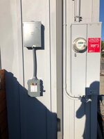
Location of the panel, note the existing exterior conduit between the gutter and MSP:
2d3cecb6e99151317c230969db75be84.jpg

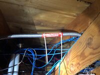
Interior bottom of the panel, note the existing two sub panel feeder lines on the back panel:
ac19684c9ecfa08547291303372c4d74.jpg

Not the best light, but a bit closer view of the bottom:
d6a40fed35748309609478e0febf6634.jpg

Thoughts, suggestions, advice? Is it acceptable to punch a new 3/4” hole in the back panel between the breaker bars and the neutral? Seems to me like that also might not be copacetic with general practice or code.


Sent from my iPhone using The Garage Journal mobile app
 

Attachments

  • 2d3cecb6e99151317c230969db75be84.jpg
    2d3cecb6e99151317c230969db75be84.jpg
    106.7 KB · Views: 0
  • ac19684c9ecfa08547291303372c4d74.jpg
    ac19684c9ecfa08547291303372c4d74.jpg
    99 KB · Views: 0
  • d6a40fed35748309609478e0febf6634.jpg
    d6a40fed35748309609478e0febf6634.jpg
    107.1 KB · Views: 0
Last edited:
To avoid these ads, REGISTER NOW!

walta

Well-known member
Joined
Jan 13, 2017
Messages
2,309
Location
Dutzow Missouri
Before you get too invested in the original panel, are the buss bars in the rated to carry enough current for you install? I think most locations require a buss able to carry the main plus the solar.


Walta
 
OP
S

sfanale

Well-known member
Joined
Sep 13, 2013
Messages
203
Location
California
Before you get too invested in the original panel, are the buss bars in the rated to carry enough current for you install? I think most locations require a buss able to carry the main plus the solar.


Walta


It’s a relatively new (4years) Eaton panel with new 200a service. Wouldn’t think I’d run into issues on that front. This is where the 120 rule applies correct? 200x1.2-200= 40a capacity for my solar and I’m only installing a 30a breaker for my total solar. If I’m understanding... should be fine right?


Sent from my iPhone using The Garage Journal mobile app
 
Last edited:
OP
S

sfanale

Well-known member
Joined
Sep 13, 2013
Messages
203
Location
California
annual production doesn't matter, kW/kVA/amperage matters.


It’s 4.65kw system. 15x panels @ 310watt with micro inverters. Just so we are clear here, both the solar wholesale company checked the panel for this, as well as the local engineer I hired to create my permit plans. Unless I’m not understanding something about the 120% rule... I should be clear.


Sent from my iPhone using The Garage Journal mobile app
 

Git

Well-known member
Joined
May 18, 2008
Messages
6,894
Location
S Cal
Don't forget - you need a disconnect which is usually right before you go into the panel. Maybe install the disconnect under the panel for now and then go through the wall from the back of the disconnect?

What kind of inverter?

I believe your good with a 30 amp breaker on a 200 amp service

NEC705. 12(B)(2)(3)(b) states that where there are two power sources, (the grid and the solar inverter), the sum of their breakers cannot equal more than 120% of the busbar rating of the breaker box.

Grid-tied Solar and the Dreaded 120% Rule
 
Last edited:
OP
S

sfanale

Well-known member
Joined
Sep 13, 2013
Messages
203
Location
California
Don't forget - you need a disconnect which is usually right before you go into the panel. Maybe install the disconnect under the panel for now and then go through the wall from the back of the disconnect?

What kind of inverter?

I believe your good with a 30 amp breaker on a 200 amp service

NEC705. 12(B)(2)(3)(b) states that where there are two power sources, (the grid and the solar inverter), the sum of their breakers cannot equal more than 120% of the busbar rating of the breaker box.

Grid-tied Solar and the Dreaded 120% Rule


Yep yep, I have all those details covered. I am applying for permitting with SD so this isn’t a rogue DIY operation. I’ll have to pass inspection with the city and SDGE utility.

My question is related to IF I am allowed to punch new knockouts into that MSP. I appreciate the help to make sure I have my bases covered, but I’m not looking for a system review. I’m curious what rules apply to putting NEW holes into a MSP. Specifically if there are no precut knockout holes where I want to put one: on the back of the panel against the wall so I can bring new THHN wire in from the wall.


Sent from my iPhone using The Garage Journal mobile app
 

wyliesdiesels

Well-known member
Joined
Aug 14, 2012
Messages
19,983
Location
Modesto, CA
Yep yep, I have all those details covered. I am applying for permitting with SD so this isn’t a rogue DIY operation. I’ll have to pass inspection with the city and SDGE utility.

My question is related to IF I am allowed to punch new knockouts into that MSP. I appreciate the help to make sure I have my bases covered, but I’m not looking for a system review. I’m curious what rules apply to putting NEW holes into a MSP. Specifically if there are no precut knockout holes where I want to put one: on the back of the panel against the wall so I can bring new THHN wire in from the wall.


Sent from my iPhone using The Garage Journal mobile app

yeah theres no rule prohibiting punching your own knockouts. its done all the time.
 
OP
S

sfanale

Well-known member
Joined
Sep 13, 2013
Messages
203
Location
California
Little more visible from this angle maybe:

c814d0f8f66b2b24f15c632ee415ff20.jpg

Following my crude drawing, I’d bring in 2x #8 THHN lines and a #8 ground wire. Run those down the right wall, over the other wires and into a 30amp at the bottom.

Sent from my iPhone using The Garage Journal mobile app
 

Attachments

  • c814d0f8f66b2b24f15c632ee415ff20.jpg
    c814d0f8f66b2b24f15c632ee415ff20.jpg
    106.4 KB · Views: 0

tyme2par4

Well-known member
Joined
May 16, 2016
Messages
571
Location
NH
My only concern about putting a knockout in your proposed location is that you may hit a stud inside the house. You are right on the corner of the structure, so it's likely that there is a 2x4 stud in that location.
The other option you could do is back feed one of the sub panels. It would depend on how full your subs are though.
 
OP
S

sfanale

Well-known member
Joined
Sep 13, 2013
Messages
203
Location
California
Back feed isn’t a great option for a few reasons. You’re also right about the knockout location and the corner studs... it’s very close but I am pretty sure I have room because the 100a subpanel feeder clears it at the bottom. I would be right on the line of the breaker/bus bar back plate.


Sent from my iPhone using The Garage Journal mobile app
 

nadogail

Well-known member
Joined
Jan 23, 2009
Messages
31,909
Location
Coronado, CA
IMHO, your solar panels will feed an inverter that will have a built in DC Disconnect the AC from the inverter will feed a AC disconnect that will feed your house. In my own home the AC from the inverter feeds through the sub panel inside the house. The conduit from the inverter to the sub panel needs to be marked that it is a Solar circuit, and the Sub Panel marked that it is fed from multiple (in this case 2) sources.

I too am a SDG&E customer, PM me and I can walk you through my installation.
 

dcg9381

Well-known member
Joined
Jun 20, 2018
Messages
11,627
Location
Austin, TX
IMHO, your solar panels will feed an inverter that will have a built in DC Disconnect the AC from the inverter will feed a AC disconnect that will feed your house. In my own home the AC from the inverter feeds through the sub panel inside the house. The conduit from the inverter to the sub panel needs to be marked that it is a Solar circuit, and the Sub Panel marked that it is fed from multiple (in this case 2) sources.
.

Note, I do not know your particular power company.
Here, the DC disconnect on the inverter "might" work if the inverter is mounted outside the home and "readily accessible".

My POC REQUIRES AC and DC disconnects, readily accessible, labelled, OUTSIDE the structure. I have a 2019 solar system with "Rapid Shutdown" technology (NEC approved) that makes the physical disconnects unnecessary. POC does not care and still wants the physical disconnect....

I'd ask the POC when you figure out the final configuration to make sure you don't end up with a bunch of re-work. I know that other POCs may require lightening and surge arrest equipment.
 
To avoid these ads, REGISTER NOW!
OP
S

sfanale

Well-known member
Joined
Sep 13, 2013
Messages
203
Location
California
IMHO, your solar panels will feed an inverter that will have a built in DC Disconnect the AC from the inverter will feed a AC disconnect that will feed your house. In my own home the AC from the inverter feeds through the sub panel inside the house. The conduit from the inverter to the sub panel needs to be marked that it is a Solar circuit, and the Sub Panel marked that it is fed from multiple (in this case 2) sources.

I too am a SDG&E customer, PM me and I can walk you through my installation.


I should have been more clear... in my application back feed from the sub isn’t ideal. Mostly due to some space restrictions and the need to have the external ac disconnect exterior to the home. Once I’ve brought the wires outside to disconnect, I might as well just go right into the main.

Anyway, I submit my permits to San Diego DSD for approval this morning so hopefully I’ll be installing in a week or two. Already got The initial net metering wrapped up with SDGE, just have to get the city inspection post install so the utility can swap me over.


Sent from my iPhone using The Garage Journal mobile app
 

Git

Well-known member
Joined
May 18, 2008
Messages
6,894
Location
S Cal
IOnce I’ve brought the wires outside to disconnect, I might as well just go right into the main.

That was the point I was trying to make when you thought I was giving you a 'system review'...
 

nadogail

Well-known member
Joined
Jan 23, 2009
Messages
31,909
Location
Coronado, CA
dcg9381 My power company is San Diego Gas & Electric and the inverter and AC disconnect are mounted on an exterior wall.
 

alfredeneuman

Well-known member
Joined
Mar 3, 2011
Messages
4,580
Location
Fullerton, CA
I notice what appears to be several NM wires through the LR condulet on the bottom of the panel. NM isn't allowed to be outdoors, even in conduit.
If anything, your new KO should be used for those cables. It would free up the bottom for your solar installation.
 
OP
S

sfanale

Well-known member
Joined
Sep 13, 2013
Messages
203
Location
California
That was the point I was trying to make when you thought I was giving you a 'system review'...

I may have misunderstood in that case. My plan is to mount the AC disconnect to the left of the main, then IN THE WALL go to the back of the main panel if I can.
 
OP
S

sfanale

Well-known member
Joined
Sep 13, 2013
Messages
203
Location
California
I notice what appears to be several NM wires through the LR condulet on the bottom of the panel. NM isn't allowed to be outdoors, even in conduit.
If anything, your new KO should be used for those cables. It would free up the bottom for your solar installation.

Yes, I noticed that when I opened the panel to start this planning. When I had AC installed, they pulled those lines and added the conduit. I agree that I *should* move those into a new KO, then recycle their conduit/LB for my solar, but I am concerned about the romex being too short. I guess I could move the fuses up to buy a few inches of length. I am hesitant to add that to my project scope unless the inspector for the solar really makes me.

In my research for this project, I found that solar installers in SD seem to use #10 THWN from the roof junction box, housed in alumiflex conduit, all the way down to the combiner box. I would have guessed they use romex in the attic, then transition to THWN in an external jbox. Is running THWNt common just to only have to stock a single wire type? or not have to junction the wire in another box?
 

alfredeneuman

Well-known member
Joined
Mar 3, 2011
Messages
4,580
Location
Fullerton, CA
but I am concerned about the romex being too short.

The new route with the connector in the back should be shorter.
As it stands the cables come past the panel to below the bottom before coming up to the breakers. The new route comes straight to the connector which is higher. You may have to even cut some wire off
 
OP
S

sfanale

Well-known member
Joined
Sep 13, 2013
Messages
203
Location
California
The new route with the connector in the back should be shorter.
As it stands the cables come past the panel to below the bottom before coming up to the breakers. The new route comes straight to the connector which is higher. You may have to even cut some wire off

yea, could be ok. Right now I know it works, so if i can avoid touching it... That is my preference. We will see how things progress with the inspections.
 

alfredeneuman

Well-known member
Joined
Mar 3, 2011
Messages
4,580
Location
Fullerton, CA
We will see how things progress with the inspections.
How many electrical inspections do you think there will be?
Chances are, just 1
(You have to do the work before you call for an inspection.)
You don't want to get it all done, be turned down, and have to do it over again
Was there a permit pulled when they ran the NM inside of the conduit?

I'm just trying to spare you from some unnecessary grief :)
 
OP
S

sfanale

Well-known member
Joined
Sep 13, 2013
Messages
203
Location
California
How many electrical inspections do you think there will be?
Chances are, just 1

One inspection by city for sure. Possibly one by SDGE, but they might just phone it in.

(You have to do the work before you call for an inspection.)

Yep... just waiting for my permit approval before I start the work.

You don't want to get it all done, be turned down, and have to do it over again

My experience with inspections thus far is they have been very superficial for common place changes. For example my MSP upgrade, the inspector didn't even open the panel. I know that its a total dice roll depending on the inspectors mood, weather patterns, the wind, etc...

Was there a permit pulled when they ran the NM inside of the conduit?

Highly doubtful.

I'm just trying to spare you from some unnecessary grief :)

Appreciated. Though I am a glutton for punishment.
 
OP
S

sfanale

Well-known member
Joined
Sep 13, 2013
Messages
203
Location
California
Just not notice today my permit was issued, so time to tear some holes in the roof. I am going to attempt to document things as I go, but sometimes I get too caught up and just tear through a project without taking pictures.
 
OP
S

sfanale

Well-known member
Joined
Sep 13, 2013
Messages
203
Location
California
Took the day off yesterday and started drilling holes in my roof. [emoji15] I started with laying everything out best I could with tape measure, crayon, and string lines:

88e8d4132a671f70c90af75e149a5a06.jpg

dc686ee1e4d0a953a0553203a93bd330.jpg

I marked out the trusses, and made sure my lines for mounting the support rails were nice and parallel. Then I started with the mounting system for the Snap-n-rack rails. It’s a pretty easy install, basically:

Drill 1/4” hole through roof into top cord of the truss
50dbfd61d02e5f9583edab7d2a14a9a9.jpg

Lift row of shingles above hole to fit Snap-n-Rack flashing and add sealant to the hole and around flashing opening
3eb75feec11a3282237811d7d73d10bb.jpg

Then drive this long 1/4” lag through the L-mounting foot, flashing, and into the truss
8de25222f3ee2f44ed3ba536e2c48fe6.jpg


29bb053768959dd861753582e01883b6.jpg

Took me about half a day for the layout and then about 20x of the mounts. I have about another 25 to finish this weekend so I can lay the rails down.
9625f184bd718522fef11f240560634e.jpg


Progress!


Sent from my iPhone using The Garage Journal mobile app
 

Attachments

  • 3eb75feec11a3282237811d7d73d10bb.jpg
    3eb75feec11a3282237811d7d73d10bb.jpg
    180.3 KB · Views: 0
  • 8de25222f3ee2f44ed3ba536e2c48fe6.jpg
    8de25222f3ee2f44ed3ba536e2c48fe6.jpg
    159.4 KB · Views: 0
  • 29bb053768959dd861753582e01883b6.jpg
    29bb053768959dd861753582e01883b6.jpg
    214.1 KB · Views: 0
  • 9625f184bd718522fef11f240560634e.jpg
    9625f184bd718522fef11f240560634e.jpg
    195.1 KB · Views: 0
  • 50dbfd61d02e5f9583edab7d2a14a9a9.jpg
    50dbfd61d02e5f9583edab7d2a14a9a9.jpg
    265 KB · Views: 0
  • dc686ee1e4d0a953a0553203a93bd330.jpg
    dc686ee1e4d0a953a0553203a93bd330.jpg
    241.6 KB · Views: 0
  • 88e8d4132a671f70c90af75e149a5a06.jpg
    88e8d4132a671f70c90af75e149a5a06.jpg
    155.9 KB · Views: 0

Git

Well-known member
Joined
May 18, 2008
Messages
6,894
Location
S Cal


Looks good - but I didn't think the metal flashing was supposed to extend past the bottom edge of the shingle like that, to prevent moisture and debris from accumulating underneath?

edited to add - I found this

https://snapnrack.com/wp-content/uploads/2019/07/SNR_Ultra-Rail-Installation-Manual_v2.4.pdf

Also, most installs on asphalt roof I have seen indicate the flashing needs to go 2 courses up which requires removal of the nails in the first course above - is that not the case with snapnrack?

attachment.php


from another manufacturer

attachment.php
 

Attachments

  • TRI-493.jpg
    TRI-493.jpg
    78.1 KB · Views: 183
  • TRI-492.jpg
    TRI-492.jpg
    92.3 KB · Views: 180
  • 29bb053768959dd861753582e01883b6.jpg
    29bb053768959dd861753582e01883b6.jpg
    199 KB · Views: 0
Last edited:
OP
S

sfanale

Well-known member
Joined
Sep 13, 2013
Messages
203
Location
California
Yes you’re right. The flashings have little marks on them for the depth. Most of the flashings I had to pry out the nails above to get them high enough. However, the shingling isn’t perfect, nor did I set my lines all high enough on the singles when I laid it out so... some fall just below the shingle line like this one in my picture.

I tried to get them mostly as high as I could, but once the row is started. They gotta stay in a straight line so there are going to be some that overhang like that.


Sent from my iPhone using The Garage Journal mobile app
 
OP
S

sfanale

Well-known member
Joined
Sep 13, 2013
Messages
203
Location
California
Also, most installs on asphalt roof I have seen indicate the flashing needs to go 2 courses up which requires removal of the nails in the first course above - is that not the case with snapnrack?


I took your comment to heart and I went back to move two of the rows up 1.5” to ensure they made it I to the second course of shingles:

af275f3f8f52aaaa7d4e71decfefd0c2.jpg

Luckily I had only had to fix 10 of the 45, so not a huge rework. Just followed the same procedure and sealed up the old hole with plenty of roof sealant to shed water. Two rows were already deep enough first instal and two rows were even to the bottom of the shingles. I checked the top of the even ones and they still slip under the second course, (about 1/4”). I also checked where two singles butted and made sure there wasn’t a little keyhole over the top of the flashing, so I think those rows are fine.

Then I started the racking. I took my time adjusting the rails starting bottom and top, then using a string to ensure all the rails were as co-planar as I could get them. Ran the string several different directions (lengthwise, across all 6, and diagonal both directions) making adjustments until I felt it was all pretty flat:

fc9a8f6cf88929ab1c1ac997bcc9e5ce.jpg

Torqued everything to the recommended 12ft/lbs per Snap-n-Rack manual (lookin’ at you Git!). Last step for the day was to consider the micro inverter layout and wire paths. I called out the rough locations of the individual panels, then the seemingly ideal placement for the micros. I tested the layout with the actual cables, but didn’t install any wires just yet:

8e476ceff977952666222717489a6901.jpg

Tomorrow, I’ll attempt to pull conduit through the wall into the attic and hopefully get some wiring pulled.


Sent from my iPhone using The Garage Journal mobile app
 

Attachments

  • af275f3f8f52aaaa7d4e71decfefd0c2.jpg
    af275f3f8f52aaaa7d4e71decfefd0c2.jpg
    302.5 KB · Views: 0
  • 8e476ceff977952666222717489a6901.jpg
    8e476ceff977952666222717489a6901.jpg
    223.5 KB · Views: 0
  • fc9a8f6cf88929ab1c1ac997bcc9e5ce.jpg
    fc9a8f6cf88929ab1c1ac997bcc9e5ce.jpg
    200.3 KB · Views: 0
Last edited:
OP
S

sfanale

Well-known member
Joined
Sep 13, 2013
Messages
203
Location
California
But if progress today. Got the conduit pulled through the attic:

99843121fc94225d90ee2aecae57fe7c.jpg

And the boxes mounted outside. It was a real pain to fish the conduit from the ac disconnect to MSP, but managed it:

3a15b8b0704af4ee05666f68f708b0d4.jpg

There were some obstructions in the wall and things to work the conduit around so that’s why I was forced to leave such a gap between the boxes. It’s not exactly the clean perfect vision I had, but pretty close.

Panels go on the roof tomorrow hopefully, then wiring Thursday, and inspection Friday.


Sent from my iPhone using The Garage Journal mobile app
 

Attachments

  • 99843121fc94225d90ee2aecae57fe7c.jpg
    99843121fc94225d90ee2aecae57fe7c.jpg
    94.6 KB · Views: 0
  • 3a15b8b0704af4ee05666f68f708b0d4.jpg
    3a15b8b0704af4ee05666f68f708b0d4.jpg
    70.3 KB · Views: 0

Git

Well-known member
Joined
May 18, 2008
Messages
6,894
Location
S Cal
I agree - looking good.

I think you made the right move reworking those. As you noted, not all roofers make each course perfectly parallel to the previous course. In the big scheme of things, properly locating the mounting on the shingle is more important than having straight, parallel rows. When it comes time to attach the panels to the racking, a couple of inches off either way is really not going to make much of a difference.

I have posted this before, but if you have the time, it is well worth the read with a lot of good pics. I really learned a lot from this post. In the end, the guy started his own solar business

https://www.solarpaneltalk.com/foru...eally-bad-looking-for-some-help-advice-please
 
OP
S

sfanale

Well-known member
Joined
Sep 13, 2013
Messages
203
Location
California
I agree - looking good.

I think you made the right move reworking those. As you noted, not all roofers make each course perfectly parallel to the previous course. In the big scheme of things, properly locating the mounting on the shingle is more important than having straight, parallel rows. When it comes time to attach the panels to the racking, a couple of inches off either way is really not going to make much of a difference.

I have posted this before, but if you have the time, it is well worth the read with a lot of good pics. I really learned a lot from this post. In the end, the guy started his own solar business

https://www.solarpaneltalk.com/foru...eally-bad-looking-for-some-help-advice-please

I will read through this later tonight.

One quick question. Do I need to ground the AC disconnect box? It didnt come with a ground bar or even a ground screw, but I would think any metal box needs to be grounded right?
 
To avoid these ads, REGISTER NOW!
Top Bottom