To avoid these ads, REGISTER NOW!

11b30b4’s Craftsman (100) 103.23130 & (150) 103.24531 15.5" Drill Press rebuild

11b30b4

Well-known member
Joined
Jul 16, 2020
Messages
1,029
Location
GA
11b30b4’s Craftsman 103.23130 & 103.24531 Drill Press rebuild

All Pics have been fixed and uploaded to GJ.

View media item 108492

This thread covers the rebuilding of two drill presses. The first is a Craftsman 100 series (103.23130) and is mostly covered in the first two pages of this thread. The second drill press is a Craftsman 150 series (103.24531) and begins on page 3 of this thread. Thank you for your interest.


Now on to the topic…
In July of 2020 I rebuilt my early 70’s Craftsman 15” drill press (113.213780) and I found that I really enjoyed the process and wanted another press to work on. I quickly knocked out my early 80’s 8” Craftsman benchtop drill press (113.213722) rebuild and was shocked at just how much quality was lost between the 70s and 80s. I knew at some point I wanted to replace my benchtop 8” with a 12” (possibly a Rikon) but I kept coming back to Frank Lee’s thread here on the TGJ for more information and lurking.

I first became aware of Frank’s thread when I was searching the internet for information on how to rebuild the 113 drill press. I quickly realized that Frank was the subject matter expert on the 100 and 150 presses. Frank even posted in my 113 rebuild thread providing some helpful advice. For me, that was like Bruce Lee coming to my Martial Arts class and giving me advice. If you are new to the forum defiantly check out Franks thread here:
https://www.garagejournal.com/forum/showthread.php?t=227480

I digress, after reading through Franks thread several times, I apparently became infected with the 100 press bug. I started searching locally for a used 100 or 150 press. Offer-up, Craigs list, local classifieds, and Facebook marketplace. After several deals fell through, I found a 100 series benchtop press for sale for $100.00 about 2 hours from me. The add was a month old so I assumed the press was already sold but I messaged the seller anyway. I asked if he still had the press and if he would take $50.00 for it. To my surprise he said yes and I now have this press. Even better, for an additional 10 bucks he drove the press out to me. I knew from the pictures posted that it was very rusty and had been in a barn for decades, but at $60.00 I had to grab it.

Here are some pics.

View media item 108407
View media item 108399
View media item 108411
View media item 108409
View media item 108402
View media item 108403
View media item 108405
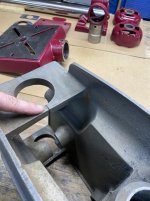
As you can see, I have my work cut out for me. Right off I knew that one of the feed handle rods was broken off in the hub, but I have the rod and all the knobs. Also, the hub is dented flat (side closets to the feed stop in the pic below). Next, I noticed the feed stop spacer and feed stop lock nut were missing as well as the chuck key. Also, the headstock lock handle was missing. All of the badges are present but in bad shape. The Motor (Craftsman ½ HP 115.6962) was just as rusty an when I plugged it in is spun then seized. I was able to spin it by hand but its rough, I do not know if it can be salvaged until I get it open.

View media item 108406
View media item 108401
View media item 108400
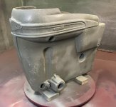
I have removed the motor and started to disassemble it. I have very limited experience with electrical motors, and this is the first one I have worked with that has a flat capacitor in the base. I am in the process of getting the seized pulley off the motor shaft without damaging either.

View media item 108412
View media item 108408
View media item 108410
View media item 108404
Not to get ahead of myself but I have been inspired by Frank’s thread here on GJ as well as two other threads on OWWM here (I later figured that these threads are also here on GJ):

http://www.owwm.org/viewtopic.php?f=1&t=114313

http://www.owwm.org/viewtopic.php?f=1&t=176198&sid=dedd2641d9afddf881ca948edcb615f3

I doubt I will go as far as jtbinvalrico went with his restoration, but I will do my best to do a good job on this machine.

Dating this press is difficult, based on what Frank has said, I know the following:
I have a tilt table = Before 1956
I have the original floor base casting = Before 1951
I do not have a rapid feed stop = Before 1956
External feed return tension adjustment= Early 100 series
Head stock lock type is = Before 1950
The motor has a stamped code of F1 50 = Possibly 1950 manufacture

The odd thing is the motor mount, it is the ribbed type and that is after 1951. My guess is that this press was a 1949-1950 manufacturer. I suppose it could have been made before 1950 and the original owner may have replaced the motor mount? Who knows, regardless it is an early 100 series. Another oddity is the Philips head screws used to hold the head frame trim on. I suppose they could have been used to replace the slotted (flat head) machine screws but the hey here is that they are not panel screws, so unless the original owner just forced some screws into panel screw holes, these babies date the machine prior to 1951.

My game plan is to safely get the pulley off the motor (Possibly using GirlInAgarage’s method), disassemble the motor and make an assessment on it. Next, complete the disassembly of the press. The quill is completely seized so that will be fun.

Well that is my progress so far. I welcome your input and thanks for the interest.
 
Last edited:
To avoid these ads, REGISTER NOW!

FrankLee

Well-known member
Joined
Sep 13, 2010
Messages
3,554
Location
seMI, 48317
You do have your work cut out for you, but other machines in similar condition have been resurrected successfully. I'm looking forward to following your progress.
 
OP
1

11b30b4

Well-known member
Joined
Jul 16, 2020
Messages
1,029
Location
GA
Thank you Frank.

Ok so I have continued to disassemble the press. The motor pulley is still firmly frozen to the motor shaft. Everything I have tried so far has failed so tomorrow, we move on to the torch… It may all be in vain since I found a crack in the motor end frame (switch end).

View media item 108420
And we still have no real idea if the motor is still viable. I am predicting a replacement motor will be needed but we will see.

I did find another date code, this time its on the motor capacitor 5-2-50, so its look more like this is a 1950 press.

View media item 108422
I have removed the feed stop, pinion assembly, and quill lock.

View media item 108414
View media item 108423
The chuck is rusted shut and had a bit stuck in it, that will be fun to get off…

View media item 108415
I will definitely need to find a headstock lock handle; this one is missing.

View media item 108421
Everything that has been removed is soaking in evaporust.

View media item 108419
View media item 108416
Anyone have any idea what these two holes are?

View media item 108417
So the quill is still stuck inside the press as is the spindle pully assembly. I do not see any other parts holding them in place so this must be the rust or rust and dried grease etc… I welcome suggestions on how to get them out without damaging them.

View media item 108418
That is my progress so far. Thanks for the interest.
 
Last edited:

FrankLee

Well-known member
Joined
Sep 13, 2010
Messages
3,554
Location
seMI, 48317
My comments below.

Thank you Frank.

Ok so I have continued to disassemble the press. The motor pulley is still firmly frozen to the motor shaft. Everything I have tried so far has failed so tomorrow, we move on to the torch… It may all be in vain since I found a crack in the motor end frame (switch end).

https://i.imgur.com/i8wukm3.jpg

And we still have no real idea if the motor is still viable. I am predicting a replacement motor will be needed but we will see.

I did find another date code, this time its on the motor capacitor 5-2-50, so its look more like this is a 1950 press.

http://i.imgur.com/zpeZZzS.jpg

That crack is not a good, but it still may refurbish ok. If it doesn't, it would be a good learning experience. There is an end cap on ebay ;).


I have removed the feed stop, pinion assembly, and quill lock.

http://i.imgur.com/YCXI8HX.jpg

http://i.imgur.com/7DR5wUz.jpg

The chuck is rusted shut and had a bit stuck in it, that will be fun to get off…

http://i.imgur.com/moPLTI1.jpg

I will definitely need to find a headstock lock handle; this one is missing.

http://i.imgur.com/efwu6om.jpg

I often recommend buyers to remove that head lock handle. Once the head frame is positioned, it will likely never get used.

Everything that has been removed is soaking in evaporust.

http://i.imgur.com/mFvJVcx.jpg

http://i.imgur.com/Hr3dkGp.jpg

Anyone have any idea what these two holes are?
Those are likely for a custom switch. It looks like a handi-box was there first and then a toggle switch in the lower hole. I frequently find head lock handles missing or moved to the right side when handi-boxes are installed.

http://i.imgur.com/SVEMPrF.jpg

So the quill is still stuck inside the press as is the spindle pully assembly. I do not see any other parts holding them in place so this must be the rust or rust and dried grease etc… I welcome suggestions on how to get them out without damaging them.
Take a look through the thread below for some ideas. Try to remove the spindle and spindle pulley assembly first. Then, the quill from the head casting.
https://www.garagejournal.com/forum/showthread.php?t=457782
.

http://i.imgur.com/N7PewmA.jpg

That is my progress so far. Thanks for the interest.
 
Last edited:
OP
1

11b30b4

Well-known member
Joined
Jul 16, 2020
Messages
1,029
Location
GA
Frank, thank you for the information. I ordered the end cap, and I am very appreciative for that.

I hear you on the headstock lock handle. Its not something I need any time soon. I will want it eventually to complete the rebuild but its just an aesthetic thing and my OCD.

The holes most likely being for a switch and handi-box is what I was thinking as well.

I have attempted to remove the spindle and both the spindle, and the pulley are firmly stuck. I looked through the thread you recommended, thank you for that. I will talk about my plan going forward below.

To the update,

I finally got the pulley off the motor. This was accomplished buy using some bar stock and a duel claw puller. Sorry I forgot to take a pic but I basically used the same method Frank did on one of his machines. The thing that made the difference was hitting the pulley and shaft with a torch for a minute and it came off fairly easy.

Once I had the pulley off, I cleaned the ends of the shaft and removed any burs.

View media item 108430
The motor came apart easy and I took a few pics so that reassembly would not be as much a mystery as it was on my 8” rebuild.

View media item 108425
View media item 108431
View media item 108432
View media item 108437
View media item 108433
View media item 108424
View media item 108428
View media item 108427
View media item 108439
Most of the badges are removed and look ok, still need to clean them up.

View media item 108442
View media item 108429
View media item 108434
I still need to pull the one on the floor base but that can wait.

All the metal bits are sitting in Evaporust or simple green.

View media item 108426
View media item 108438
I managed to get the table to move on the column, but the headstock is still stuck to the column. I have tried PB, heat, WD-40, and the pulley puller to no avail. I do not want to crack or break the head.

View media item 108441
Also, the Quill, spindle, and spindle pulley assemble are also still stuck in the headstock. I put the pinion back in and tried to move the quill with no luck and I have tried PB, heat, etc… so my new plan is this. I built a box, lined it with 7mil plastic. Lowered the head into it and tomorrow I will grab 5 gallons of vinegar.

View media item 108436
View media item 108435
I will let that soak for a day or two and see if that helps release the parts. If I can get these parts out then I will figure out how to get the headstock off the column.

Well that’s it for now, thanks for the interest.
 
Last edited:

FrankLee

Well-known member
Joined
Sep 13, 2010
Messages
3,554
Location
seMI, 48317
Frank, thank you for the information. I ordered the end cap, and I am very appreciative for that.

I hear you on the headstock lock handle. Its not something I need any time soon. I will want it eventually to complete the rebuild but its just an aesthetic thing and my OCD.

The holes most likely being for a switch and handi-box is what I was thinking as well.

I have attempted to remove the spindle and both the spindle, and the pulley are firmly stuck. I looked through the thread you recommended, thank you for that. I will talk about my plan going forward below.

To the update,

I finally got the pulley off the motor. This was accomplished buy using some bar stock and a duel claw puller. Sorry I forgot to take a pic but I basically used the same method Frank did on one of his machines. The thing that made the difference was hitting the pulley and shaft with a torch for a minute and it came off fairly easy.

Once I had the pulley off, I cleaned the ends of the shaft and removed any burs.

https://i.imgur.com/Rfsinkf.jpg

The motor came apart easy and I took a few pics so that reassembly would not be as much a mystery as it was on my 8” rebuild.

https://i.imgur.com/z6dSnes.jpg

https://i.imgur.com/qMtvxFo.jpg

https://i.imgur.com/t9UnDh7.jpg

https://i.imgur.com/tyw24OM.jpg

https://i.imgur.com/IGAy2Nr.jpg

https://i.imgur.com/J9NuZP5.jpg

https://i.imgur.com/J9NuZP5.jpg

https://i.imgur.com/RlNm9wc.jpg

https://i.imgur.com/W0ohpF4.jpg

Most of the badges are removed and look ok, still need to clean them up.

https://i.imgur.com/6IAD8fL.jpg

https://i.imgur.com/4sqYX0i.jpg

https://i.imgur.com/dBQahmA.jpg

I still need to pull the one on the floor base but that can wait.

All the metal bits are sitting in Evaporust or simple green.

https://i.imgur.com/iYEVHr9.jpg

https://i.imgur.com/BNx4oIT.jpg

I managed to get the table to move on the column, but the headstock is still stuck to the column. I have tried PB, heat, WD-40, and the pulley puller to no avail. I do not want to crack or break the head.

https://i.imgur.com/fIlURjT.jpg

Also, the Quill, spindle, and spindle pulley assemble are also still stuck in the headstock. I put the pinion back in and tried to move the quill with no luck and I have tried PB, heat, etc… so my new plan is this. I built a box, lined it with 7mil plastic. Lowered the head into it and tomorrow I will grab 5 gallons of vinegar.

https://i.imgur.com/hMVow7Z.jpg

https://i.imgur.com/IvTNGiq.jpg

I will let that soak for a day or two and see if that helps release the parts. If I can get these parts out then I will figure out how to get the headstock off the column.

Well that’s it for now, thanks for the interest.
Did you get the head lock cylinders out? How about the spindle pulley retaining screws? And the bit out of the chuck?
 
Last edited:
OP
1

11b30b4

Well-known member
Joined
Jul 16, 2020
Messages
1,029
Location
GA
Frank, thanks for the reply and questions. Yes I managed to get the bit out of the chuck, that bit is toast. Heck, I am fairly sure the chuck is toast as well, however; I have another safety collar Jacobs cuck to replace it with. It the one I pulled from my 113 machine and replaced with a new one.

Also, yes I removed all the lock nuts and bolts and used a wooden dowel to pop out all the lock cylinders out. Further, the two retaining screws have been removed as well. As best as I can tell, its just old grease and rust that are holding the parts in but that stuff has the cement strength of reinforced concrete. I hope the vinegar will loosen in up in a few days.

View media item 108443
 
Last edited:
OP
1

11b30b4

Well-known member
Joined
Jul 16, 2020
Messages
1,029
Location
GA
One Classic Craftsman Drill Press and you are a tinkerer. Two Classic Craftsman Drill Presses and you are an aficionado. Three Classic Craftsman Drill Presses and you are collector. Four or more Classic Craftsman Drill Presses and you have an addition that no 12-step program will cure you of.

While working on the 100 series (technically waiting for the Vinegar to do its thing) I checked out CL and I found a 150 press for sale. I called the guy just 4 hours after he posted it and we agreed on $90.00. I promise I am not attempting reenact Frank’s 2012 and I know my wife would skin me alive if I snagged another press with me owning 4. Even if only 2 are classic 100/150 machines, I believe my wife is expecting me to sale and part with the 113 machines.

Anyway, here are the particulars for this 150 Press.
Craftsman model 103.24531 = After 1958
The Press is gold and has the external tension knob = After 1958 but an early 150
The table is standard and does not tilt; however, it does have the key storage hole = not sure that helps date it
The floor base has the new profile = possibly 1960
It has the rapid adjust feed stop = not sure that helps date it
It has the hinged motor mount with the threaded boss on the mounting plate = early 150
It has the split phase motor = possibly 1961
The feed handles are ½-13 with black knobs = not sure that helps date it
The table and headstock lock handles are the new design = not sure that helps date it
The motor stamped manufacture number is 66397 model 113.19352 = heck if I know, possibly 1966 or 1963 or even 1997. This motor may have been a replacement motor at some point?

Well here are the pics:

View media item 108493
View media item 108494
View media item 108497
View media item 108495
View media item 108496
This press is in very good shape and as far as I can see, the only thing missing is the threaded bolt for the tilt motor mount. There is almost no rust except on the column. It came apart with little effort for transport and I feel it’s a great find for $90.00. I plan on cleaning it up, re-wiring the switch, adding an internal light and putting it to use.

The 100 machine continues to bathe in vinegar, and it looks like the vinegar is doing its job.

View media item 108445
The stator cover band is way to pitted to restore to its original look. I will most likely sand blast or sand it then hit it with some primer then apply the engine turned vinyl. I looked for and was unable to find vinyl that was 1/8” striped chrome and satin to give it that original appearance. If anyone knows where to find vinyl in that pattern, that would be awesome. I do have some chrome vinyl and a cricket cutter so I could feasibly cut it in 1/8’ wide strips and paint the cover band a satin silver. This would produce a look similar to factory, but I will cross that bridge when I get to it.

I plan on taking the 100 press out of the vinegar tonight and see if I can get the quill and spindle pulley out. Then its time to figure out how to get the head off the column. If I can get the floor base off the column, I should be able to get the table off from the bottom, this would assist in working with the headstock and column.

Again, thanks for the interest.
 
Last edited:

FrankLee

Well-known member
Joined
Sep 13, 2010
Messages
3,554
Location
seMI, 48317
Your DP#4 looks like a very nice machine!

The 150 was introduced in 1958. There was no catalog that year, but drill presses with catalog number 2453 were featured in the '59, '60, '61 and '63 catalogs. Your 24531 was probably a later machine. I never could figure out what the last digit means.

It seems logical that the gold paint lasted through the 2453 period, bur there's no proof afaik. I believe the motor date code is June '63, which supports the above.

Some of the other features were available on late 100's. Idk when black knobs were used versus red knobs.
 
Last edited:
OP
1

11b30b4

Well-known member
Joined
Jul 16, 2020
Messages
1,029
Location
GA
Hello Frank, thank you for the information on the 150 press, I believe you are correct, and the press is most likely 63 ish. That still makes it older than me (I was born in 68). I am holding off on doing anything with the 150 press until I get the 100 press running or at least further along.

To the update,
The vinegar did the job or at the very least greatly helped out. After I removed the head from the bath, I washed it down with water. Once that was done, a lot of the crud was cleaned off and I could see more of what was going on with the spindle.

View media item 108446
View media item 108450
I was unaware of the set screw in the spindle collar. If Frank or someone else mentioned it before, I missed it. Further, the exploded view in the owner’s manual it is barely visible.

View media item 108449
Once I got the set screw out, the quill was still near impossible to move, I was able to tap out the spindle from the top through the hole in the pulley. Next, I used a piece of plate steel and a steel rod to knock the quill out.

View media item 108452
Next, using a larger wooden dowel from the bottom of the head, I was able to get the spindle pulley assembly out. Next, I got the chuck off and stripped all the parts.

View media item 108454
Using the blue wrench (torch) I was able to get the floor base off the column and then the table. I took the table apart and removed the data plate from the floor base.

View media item 108453
View media item 108451
View media item 108448
View media item 108456
I rotated parts from evaporust to simple green and from simple green to washed and applied a coat of WD 40 to prevent from rusting until they get polished or painted.

View media item 108455
Lastly, the column is still firmly stuck inside the headstock, so I built a new bath and filled it with all the vinegar I had on hand. I need to grab 2-4 more gallons of vinegar tomorrow and fill the bath the rest of the way up. I plan on leaving the headstock in the bath until Friday and then see what I can do to get the headstock off the column.

View media item 108447
Again, thanks for the interest.
 
Last edited:

FrankLee

Well-known member
Joined
Sep 13, 2010
Messages
3,554
Location
seMI, 48317
Hello Frank, thank you for the information on the 150 press, I believe you are correct, and the press is most likely 63 ish. That still makes it older than me (I was born in 68). I am holding off on doing anything with the 150 press until I get the 100 press running or at least further along.

To the update,
The vinegar did the job or at the very least greatly helped out. After I removed the head from the bath, I washed it down with water. Once that was done, a lot of the crud was cleaned off and I could see more of what was going on with the spindle.

https://i.imgur.com/s3CAZkO.jpg

https://i.imgur.com/EcfrMc5.jpg

I was unaware of the set screw in the spindle collar. If Frank or someone else mentioned it before, I missed it. Further, the exploded view in the owner’s manual it is barely visible.

https://i.imgur.com/vB9rZG6.jpg

Once I got the set screw out, the quill was still near impossible to move, I was able to tap out the spindle from the top through the hole in the pulley. Next, I used a piece of plate steel and a steel rod to knock the quill out.

https://i.imgur.com/HbVgQbr.jpg

Next, using a larger wooden dowel from the bottom of the head, I was able to get the spindle pulley assembly out. Next, I got the chuck off and stripped all the parts.

https://i.imgur.com/pMRgLtm.jpg

Using the blue wrench (torch) I was able to get the floor base off the column and then the table. I took the table apart and removed the data plate from the floor base.

https://i.imgur.com/9zdIiEF.jpg

https://i.imgur.com/q5DO7jL.jpg

https://i.imgur.com/tOYA4Qa.jpg

https://i.imgur.com/mlrpJCo.jpg

I rotated parts from evaporust to simple green and from simple green to washed and applied a coat of WD 40 to prevent from rusting until they get polished or painted.

https://i.imgur.com/EV2JU0D.jpg

Lastly, the column is still firmly stuck inside the headstock, so I built a new bath and filled it with all the vinegar I had on hand. I need to grab 2-4 more gallons of vinegar tomorrow and fill the bath the rest of the way up. I plan on leaving the headstock in the bath until Friday and then see what I can do to get the headstock off the column.

https://i.imgur.com/XlbqPd6.jpg

Again, thanks for the interest.

Good progress!

Have you considered electrolysis for the severely rusted parts? I prefer citric acid over vinegar or evaporust for mild/moderate rust, but for very rusted parts, I use electrolysis.
 
OP
1

11b30b4

Well-known member
Joined
Jul 16, 2020
Messages
1,029
Location
GA
Frank, I have considered electrolysis, but I have not gone down that road yet. Electricity and water make me a bit apprehensive. I will look into it in the future. I just did the vinegar this time because it was very cheap, like $2.50 per gallon cheap. I do like the evaporust and I use it quite a bit but $20.oo per gallon is steep, thankfully its reusable. BTW, I sent you a PM.

I received the endcap today along with a little surprise, thank again.
Update,
So, I started reassembling the rotor assembly. First, I put it on the lathe and cleaned up the shaft with 320 grit through 1000 grit. Once cleaned, I installed the governor assembly. That is as far as I can go until I decide on the paint for the endcaps and decide how I am going to do the stator cover band.

View media item 108458
View media item 108457
That’s the update, thanks for the interest.
 
Last edited:
OP
1

11b30b4

Well-known member
Joined
Jul 16, 2020
Messages
1,029
Location
GA
Update,

I have continued to rotate parts from evaporust to simple green then to dry and get a coat of WD-40 till further cleaning.

I drained the vinegar from the bath and washed the headstock then I tried to remove the head from the column. No dice. A lot of the rust is gone, and I have used heat, pounding with a dead blow mallet, PB in the seams, sanded the column in case there was bur or something. I have tried to pound the column in both directions and it wont budge.

View media item 108460
View media item 108459
View media item 108462
View media item 108461
So, until someone has a better idea, my next plan is to re-install the floor base and table on the column. I will raise the column then use a Scissor Jack on the table with a block of wood between the jack and the headstock. Again, the thing that most concerns me is the possibility of cracking the headstock. I am doing all I can to not crack it, but I am running out of options. Another thought that came to me is the possibility that the head may have warped over the years if that is even a possibility? Well I will let you know how this turns out.

Thanks for the interest.
 
Last edited:

FrankLee

Well-known member
Joined
Sep 13, 2010
Messages
3,554
Location
seMI, 48317
Update,

I have continued to rotate parts from evaporust to simple green then to dry and get a coat of WD-40 till further cleaning.

I drained the vinegar from the bath and washed the headstock then I tried to remove the head from the column. No dice. A lot of the rust is gone, and I have used heat, pounding with a dead blow mallet, PB in the seams, sanded the column in case there was bur or something. I have tried to pound the column in both directions and it wont budge.

https://i.imgur.com/gLuKPlz.jpg

https://i.imgur.com/kklQMui.jpg

https://i.imgur.com/LKjuaei.jpg

https://i.imgur.com/jZ2VmSt.jpg

So, until someone has a better idea, my next plan is to re-install the floor base and table on the column. I will raise the column then use a Scissor Jack on the table with a block of wood between the jack and the headstock. Again, the thing that most concerns me is the possibility of cracking the headstock. I am doing all I can to not crack it, but I am running out of options. Another thought that came to me is the possibility that the head may have warped over the years if that is even a possibility? Well I will let you know how this turns out.

Thanks for the interest.
On two occasions I had to use a jack to remove the head frame casting. One time it was successful and the other time it cracked the casting at the rear seam in one of the column bores. I can't remember which.

I would suggest to avoid using the jack on the table... use only the base. The cast iron on the table support is thinner at the lock and is more vulnerable to cracking.

I think I'd try dry ice with the jack. Stuff a rag down the column to just below the lower column bore. Dump in some dry ice pellets, wait a minute and use the jack. Set-up the jack as close to the column as possible.

More often, the bases on floor standing machines are rusted to the column.
The post at the link below shows how I remove stuck bases. It may trigger some ideas.
https://www.garagejournal.com/forum/showthread.php?p=5147377
 
Last edited:
OP
1

11b30b4

Well-known member
Joined
Jul 16, 2020
Messages
1,029
Location
GA
Frank thank you for the suggestions. Unfortunatly as soon as I posted the previous post, I figured no time like the present and grabbed the jack.

I set up the jack on the table only to realize the table would position the jack too far from the column so I removed the table. I dropped the column through the floor base resting on a work bench then used the jack between the floor base and head. There was a loud pop and the head was free. No cracks as far as I can see. So I think it was a success. I now have the head sitting in the evaporust bath and the column is covered in metal rescue and plastic wrap. I looked over your section on the stuck floor base removal methods when I first got this press. I especially like the charcoal "Extreme Method". Whatever works is a method as we use to say in the army. the dry ice is a good idea but its all water under the bridge at this point. I really appreciate you quick posting and next time I hit a snag, I will hold off on doing anything extreme until I consult with you.

Ok, everything is now disassembled and phase 1 complete. I think I will start on the stator cover band tomorrow.

Thanks for the interest.
 

FrankLee

Well-known member
Joined
Sep 13, 2010
Messages
3,554
Location
seMI, 48317
Frank thank you for the suggestions. Unfortunatly as soon as I posted the previous post, I figured no time like the present and grabbed the jack.

I set up the jack on the table only to realize the table would position the jack too far from the column so I removed the table. I dropped the column through the floor base resting on a work bench then used the jack between the floor base and head. There was a loud pop and the head was free. No cracks as far as I can see. So I think it was a success. I now have the head sitting in the evaporust bath and the column is covered in metal rescue and plastic wrap. I looked over your section on the stuck floor base removal methods when I first got this press. I especially like the charcoal "Extreme Method". Whatever works is a method as we use to say in the army. the dry ice is a good idea but its all water under the bridge at this point. I really appreciate you quick posting and next time I hit a snag, I will hold off on doing anything extreme until I consult with you.

Ok, everything is now disassembled and phase 1 complete. I think I will start on the stator cover band tomorrow.

Thanks for the interest.
Good news! Sometimes you just gotta go for it.

IIRC, the only way I could tell mine cracked was when I tightened the head frame lock and the crack opened.
 

vertguy

Well-known member
Joined
Apr 6, 2010
Messages
1,260
Location
SE WI
Re: 11b30b4’s Craftsman 103.23130 & 103.24531 Drill Press rebuild

Another option for the column is to use a piece of 3 inch PVC with one end capped. Drop in the column and fill with Evaporust. I used this method for my floor DP and it worked great.


Sent from my iPad using Garage Journal
 

lafester

Well-known member
Joined
Mar 1, 2017
Messages
2,191
Location
Northern CO
Re: 11b30b4’s Craftsman 103.23130 & 103.24531 Drill Press rebuild

I think you did not read his entire post.


Hello, if you are reading this and do not see a picture of stormtrooper below, then Imgur is blocking your access to my imbedded pictures in this thread and nothing here will make any sense without pictures.

gTvDr1w.jpg


To fix this, go here for a simple solution.
https://www.garagejournal.com/forum/showthread.php?t=465329

in closing, i should also point out that imgur will almost certainly either die or be gimped eventually. just like every other free image host that's ever been (imageshack, photobucket, tinypic, ...). i think that for important posts you make, it's worth making the extra effort to upload directly to GJ for posterity. help fight image rot! but i realize that this may be less convenient.

overall recommendation? use this setup i describe to view existing GJ posts with imgur images, but don't use imgur to share new images on here going forward because people won't be able to see them without this setup.

hope that helps :)
 
OP
1

11b30b4

Well-known member
Joined
Jul 16, 2020
Messages
1,029
Location
GA
Frank,
Well ****, I guess I will know for sure once I try to mount the head. Crossing my fingers that its not cracked.

Vertguy,
Thank you for the suggestion, I read that idea from Frank’s thread back when I was doing the 113 drill press rebuild; however, I had already purchased the Metal Rescue at the time and it seemed to work well. Just an FYI, I had some rust on the Ways for my lathe and the Metal Rescue covered in plastic wrap did the trick on them. So, for large parts or odd parts that are hard to detach and submerge, I recommend Metal Rescue. If I did not already have it on hand, the PVC pipe would have been the method I would have gone with.

Lafester,
I did read the entire post. I took pizza’s comments as a suggestion and not a forum rule. I have already gone through this when Photobucket enforced its “no forum linking rules” and I spent two days transferring all my images to Imgur then going to every forum I am a member of and relinking all the photos. I would stop using Imgur here on GJ if 1. It is a rule for the forum ( and I am not aware it is one), or, 2. GJ allows images to be imbedded between paragraphs rather than at the end of each post.

If linking from Imgur is a violation of a rule, please let me know.

Update,

Here is the column covered with Metal Rescue and plastic wrap.

View media item 108474
While the Metal Rescue was doing its thing, I started working on the stator band. I originally was hoping it would clean up better but as you can see the rust did a job to the band.

View media item 108464
So after reading through jtbinvalrico thread, I decided to try my hand at making a replacement stator band from sheet aluminum. I basically did the same thing jtbinvalrico did. Stating with a 12”x24” .091”thick sheet from HD.

View media item 108465
I cut it to the correct size with the band saw and left the ends a little longer than needed to mount it with screws to a flat piece of MDF. I wet sanded the aluminum with 320-1000 grit.

View media item 108466
Next, I polished it with Flitz and Mother Aluminum Polish and a foam attachment on a hand drill. I achieved a passable shine, not the mirror that jtbinvalrico was getting but good enough for me.

View media item 108476
Next, I used my silhouette vinyl cutter to cut out 1/8” wide clear vinyl strips and adhered them to the aluminum. Then I used some steel wool and a scotch-brite pad to rough the aluminum not covered by the vinyl.

View media item 108478
Next, I removed the vinyl and presto, I have a replacement band.

View media item 108475
Lastly, using the original band as a template, I measured and drilled the holes for the data plate then mounted it with some pop rivets. It is still unclear if the motor will even work but I am working on the assumption that it will and if it does not, I got to try something new and had fun doing it.

View media item 108467
After 24 hours, it was time to clean off the column, so I pulled the plastic wrap off and washed it off. There was still some rust on it and the pitting was significant. I would have slapped it on my lathe to clean it up, but I do not have a rest that will fit it. The largest diameter I can support is 2.5 inches. I did not want to take the time to fabricate something so I hit the column with a scotch-brite angle grinder attachment and did the best I could. After sanding and wet sanding this is how it turned out. As you can see there is significant pitting and dings in the column, but I believe it will function.

View media item 108487
View media item 108477
Next, I tried to clean up the floor base and table. The rust did its job on both. Even after grinding and sanding both are pitted significantly. I stopped working on them after a few hours, not wanting to take too much metal off them. I do not have the benefit of a super wide belt sander and I did not want to seriously damage them any worse than they already are.

View media item 108480
Next, I cleaned off all the parts getting paint then masked them off. For the color, I was planning on painting this press gold but since I got the 150 press in gold, I decided to go with a maroon. I would have preferred a darker maroon (I was shooting for something that matched the feed knobs) but the color options for spray paint are limited. I could have shot over to PPG and got some automotive paint that matched perfectly but that would have been a more involved paint job and I did not want to expend that cost and energy.

View media item 108468
View media item 108482
All the parts got metal etching primer then the maroon. A few of the internal parts for the motor got the same grey I used on the 113 press.

View media item 108486
View media item 108485
View media item 108470
View media item 108479
View media item 108481
View media item 108469
While this was going on, I rotated the head in the evaporust.

View media item 108473
Next, I pulled the masking off the parts.

View media item 108472
Here are some closed ups of the floor base and table. As you can see the pitting and damage is significant, but I believe they will still function.

View media item 108484
View media item 108483
Lastly, I moved the head to the simple green. Tonight, it will get flipped. Tuesday it can be cleaned and painted. I will be ordering the replacement bearings today as well as the replacement feed handle rods. I may begin the reassembly but without the bearings, there will be little I can assemble.

View media item 108471
Thanks for the interest.
 
Last edited:

FrankLee

Well-known member
Joined
Sep 13, 2010
Messages
3,554
Location
seMI, 48317
Frank,
Well ****, I guess I will know for sure once I try to mount the head. Crossing my fingers that its not cracked.

Vertguy,
Thank you for the suggestion, I read that idea from Frank’s thread back when I was doing the 113 drill press rebuild; however, I had already purchased the Metal Rescue at the time and it seemed to work well. Just an FYI, I had some rust on the Ways for my lathe and the Metal Rescue covered in plastic wrap did the trick on them. So, for large parts or odd parts that are hard to detach and submerge, I recommend Metal Rescue. If I did not already have it on hand, the PVC pipe would have been the method I would have gone with.

Lafester,
I did read the entire post. I took pizza’s comments as a suggestion and not a forum rule. I have already gone through this when Photobucket enforced its “no forum linking rules” and I spent two days transferring all my images to Imgur then going to every forum I am a member of and relinking all the photos. I would stop using Imgur here on GJ if 1. It is a rule for the forum ( and I am not aware it is one), or, 2. GJ allows images to be imbedded between paragraphs rather than at the end of each post.

If linking from Imgur is a violation of a rule, please let me know.

Update,

Here is the column covered with Metal Rescue and plastic wrap.

https://i.imgur.com/pG7HM2V.jpg

While the Metal Rescue was doing its thing, I started working on the stator band. I originally was hoping it would clean up better but as you can see the rust did a job to the band.

https://i.imgur.com/NqM1Qdj.jpg

So after reading through jtbinvalrico thread, I decided to try my hand at making a replacement stator band from sheet aluminum. I basically did the same thing jtbinvalrico did. Stating with a 12”x24” .091”thick sheet from HD.

http://i.imgur.com/2cTDVZY.jpg

I cut it to the correct size with the band saw and left the ends a little longer than needed to mount it with screws to a flat piece of MDF. I wet sanded the aluminum with 320-1000 grit.

https://i.imgur.com/RpDImSU.jpg

Next, I polished it with Flitz and Mother Aluminum Polish and a foam attachment on a hand drill. I achieved a passable shine, not the mirror that jtbinvalrico was getting but good enough for me.

https://i.imgur.com/owYn0bn.jpg

Next, I used my silhouette vinyl cutter to cut out 1/8” wide clear vinyl strips and adhered them to the aluminum. Then I used some steel wool and a scotch-brite pad to rough the aluminum not covered by the vinyl.

https://i.imgur.com/B0z3X5o.jpg

Next, I removed the vinyl and presto, I have a replacement band.

https://i.imgur.com/NBHsLns.jpg

Lastly, using the original band as a template, I measured and drilled the holes for the data plate then mounted it with some pop rivets. It is still unclear if the motor will even work but I am working on the assumption that it will and if it does not, I got to try something new and had fun doing it.

https://i.imgur.com/jlWiah6.jpg

After 24 hours, it was time to clean off the column, so I pulled the plastic wrap off and washed it off. There was still some rust on it and the pitting was significant. I would have slapped it on my lathe to clean it up, but I do not have a rest that will fit it. The largest diameter I can support is 2.5 inches. I did not want to take the time to fabricate something so I hit the column with a scotch-brite angle grinder attachment and did the best I could. After sanding and wet sanding this is how it turned out. As you can see there is significant pitting and dings in the column, but I believe it will function.

https://i.imgur.com/GJoynyB.jpg

https://i.imgur.com/wfpPXDH.jpg

Next, I tried to clean up the floor base and table. The rust did its job on both. Even after grinding and sanding both are pitted significantly. I stopped working on them after a few hours, not wanting to take too much metal off them. I do not have the benefit of a super wide belt sander and I did not want to seriously damage them any worse than they already are.

https://i.imgur.com/kAga4LB.jpg

Next, I cleaned off all the parts getting paint then masked them off. For the color, I was planning on painting this press gold but since I got the 150 press in gold, I decided to go with a maroon. I would have preferred a darker maroon (I was shooting for something that matched the feed knobs) but the color options for spray paint are limited. I could have shot over to PPG and got some automotive paint that matched perfectly but that would have been a more involved paint job and I did not want to expend that cost and energy.

https://i.imgur.com/hF77OaB.jpg

https://i.imgur.com/49YKx72.jpg

All the parts got metal etching primer then the maroon. A few of the internal parts for the motor got the same grey I used on the 113 press.

https://i.imgur.com/zsFP5R2.jpg

https://i.imgur.com/mxNk30q.jpg

https://i.imgur.com/8G1XQ1x.jpg

https://i.imgur.com/NZTpNB8.jpg

https://i.imgur.com/HvTnLV8.jpg

https://i.imgur.com/6cxWNr3.jpg

While this was going on, I rotated the head in the evaporust.

https://i.imgur.com/vgdi4sW.jpg

Next, I pulled the masking off the parts.

https://i.imgur.com/RaCLbec.jpg

Here are some closed ups of the floor base and table. As you can see the pitting and damage is significant, but I believe they will still function.

https://i.imgur.com/2Mplktd.jpg

https://i.imgur.com/wX70Le4.jpg

Lastly, I moved the head to the simple green. Tonight, it will get flipped. Tuesday it can be cleaned and painted. I will be ordering the replacement bearings today as well as the replacement feed handle rods. I may begin the reassembly but without the bearings, there will be little I can assemble.

https://i.imgur.com/qLJNQIF.jpg

Thanks for the interest.
You're making a ton of good progress! Keep it up!
 
To avoid these ads, REGISTER NOW!
OP
1

11b30b4

Well-known member
Joined
Jul 16, 2020
Messages
1,029
Location
GA
Frank, thank you.

Update,
Once I pulled the headstock from the simple green bath and washed it down, I noticed the seam on the top back near the column hole. It is hard to see, and I do not know if it is a crack or not.

View media item 108489
View media item 108490
Going forward, if its not a crack then great and we push on. If it is a crack, then there are two options. Option one is that this does not affect the operation of the drill press. This would seem to be a correct assumption since the Headstock lock should compress the two sides of the head rather than expand them; however, it is possible that the column works as a pivot point and the back side of the headstock expands then the lock is applied.

The second option is that this crack does affect the operation and the fix is to fabricate a bridge plate and bolt it to the headstock. I briefly messaged Frank about this last night and I believe that we can come up with a suitable solution. Of course, until we know for sure this is all conjecture.

In addition to the possible crack, I also discovered the rust did a fantastic job of completely mucking up the inside bore of most of the holes in the headstock. What do I mean by this? Well most of the holes inside the headstock are supposed to be completely smooth, think “polished” if you get my meaning. Well, polished they are not. Other than the two column holes, all the other holes are as rough as the exterior of the headstock if not more. I failed to get any pictures of this prior to me attempting to correct this issue and then prime the headstock.

I messaged Frank to find out if these holes were supposed to be smooth or not. On my 113 press, all the holes had smooth bores. Frank let me know they were supposed to be smooth so to correct this I first used a brass wire wheel. This did little to smooth the bore and only shined up the textured surface inside the holes. Taking care to not remove too much metal, I used a 240 grit sanding drum on my Foredom and smoothed the inside of all the holes I could reach. There are two holes for the quill deeper in the center of the spindle path (running top to bottom) that my Foredom cannot reach. I may have to fabricate some sort of deep reach sanding drum to access them.

Deciding to press on, I decided to remove the casting seam on the front nose of the headstock. I did this with the angle grinder and a scotch-brite disc. I also hit the lip surrounding the engine turned panel inset. I am thinking of painting this a different color from the rest of the head. I would like to keep is shinny metal (chrome-ish) but that diminishes the appearance of the engine turned panel so something contrasting will be in order. Perhaps the Craftsman dark grey I used on the 113 press or possibly black, I have not decided yet.

View media item 108488
I masked the headstock and hit it with the metal etch primer.

View media item 108491
That it for the update, thanks for the interest.

ahem
 

Attachments

  • IMG_5061.jpg
    IMG_5061.jpg
    59.8 KB · Views: 23
  • IMG_5062.jpg
    IMG_5062.jpg
    41.3 KB · Views: 22
  • IMG_5060.jpg
    IMG_5060.jpg
    77.3 KB · Views: 25
  • IMG_5063.jpg
    IMG_5063.jpg
    58 KB · Views: 23
Last edited:
OP
1

11b30b4

Well-known member
Joined
Jul 16, 2020
Messages
1,029
Location
GA
Lafester, thank you for pressing the image issue. At your insistence, I contacted Pizza to explore my options.

Pizza set me straight. I now know how to add images to GJ then embed them into a thread between paragraphs. Sooooo, this is how I will be posting all pics in this thread. I will try to go back and do this with all previous pics here and in other threads I posted in.

Update,
I ordered some 3” long sanding drums from Climax Metals and attached them to the hand drill. I was able to get to all the bore holes inside the headstock. That being said, the rust and pitting damage is extensive. Keep in mind that all these are supposed to be smooth and shiny. After using the 120 grit on the drums, I used a brass brush wheel, and this is as good as they got. You can still see some pitting and they are definitely not smooth, but it’s an improvement from what they originally looked like. As long as I didn’t take too much metal, they should function.

View media item 108386
View media item 108389
View media item 108388
View media item 108387
View media item 108390
After, that was done I masked off the bores and hit the head with the maroon paint.

View media item 108398
Next, I cleaned up the spindle with a brass wheel then buffed it. There is significant damage and pitting but the area where the bearing sits is fairly clean. Also, there are some dings in the splines but I believe these will also have minimal effect on the operation and runout.

View media item 108391
View media item 108395
View media item 108394
View media item 108393
View media item 108392
I was able to grab a very nice looking chromed original headstock lock handle so I wanted to see where the rest of my chrome stood. This is the hub. If you recall it had a flattened “dented” side that I was able to smooth out somewhat with a brass hammer. Anyway, this his how the hub looks after cleaning and rust removal.

View media item 108396
So, I figured I would try the Coke and aluminum foil thing. Well its shinier…. Damn pitting.

View media item 108397
So, there is a local guy who does chrome and has been doing it for year. Once this press is reassembled and working, I may pull the chrome and have it redone but for now, as long as it functions, we are good.

My bearing should arrive today or tomorrow. Once I have them, I can reassemble the motor and see if where we are.

Thanks for the interest.
 
Last edited:
OP
1

11b30b4

Well-known member
Joined
Jul 16, 2020
Messages
1,029
Location
GA
Update,
So here we are Monday and still no bearings. Hopefully they will arrive today or tomorrow. What good is a tracking number if it does not tell you when the estimated delivery date is????

Friday, I finished painting the headstock. After the maroon was cured, I masked off the “nose” and surround and painted it hammered black.

View media item 108661
Here is a pic after the masking was removed.

View media item 108666
Once that was cured, I removed the remaining masking and polished all the bore holes.

Next, I decided to polish up the pulleys and cap. The pitting is on everything. For these I chucked them on the lathe and hit them with 80 grit -320 grit, then wet sanded them 400 grit -1000 grit.

View media item 108662
View media item 108664
Next, I decided to work on the feed knobs. I ordered new rods from Oldironowner here on GJ and hopefully they will also arrive today or tomorrow. He messaged me this morning to see if they arrived yet. Outstanding follow-up, I am sure the quality of the rods will be first rate and I can recommend him for anyone looking for rods.

So for the knobs, each of them had some deep gouges in one side. I figured they would not buff out but I could sand them out so I chucked one of the old and pitted rods in the lathe. Running in the opposite direction I hit the knobs with 320-1000 grit, wet sanding the 400 and up grit. I cleaned the knobs then it them with the Meguiar's cleaner wax (thank you Frank Lee). They cleaned up nicely.

View media item 108665
In this pic the one on the left has been cleaned up.

View media item 108663
So, Saturday I ended the working on the press with everything cleaned up and ready for assembly.

View media item 108667
View media item 108669
View media item 108668
Sunday, I decided to assemble what I could sans bearings.

View media item 108672
View media item 108671
Lastly, this morning I messaged Mattblast about making a new label for the floor base model number data plate. Mine is in really bade shape.

View media item 108670
I am planning on fabricating an internal light similar to the one that comes on the 113 Craftsman/Emerson drill press. I have all the stuff to do it but I am have yet to start that modification.

That is it for the update. Thanks for the interest.
 
OP
1

11b30b4

Well-known member
Joined
Jul 16, 2020
Messages
1,029
Location
GA
Quick update,

Rods arrived yesterday from OldIronOwner. Outstanding quality and I highly recommend him. Still waiting on the bearings from Direct. According to the tracking number they have been in Atlanta since Sunday but they have not moved since. I even called USPS and got the "we have to wait 14 days until we can do anything" line. I expect it has to do with the Christmas overload on the mail system. Anywho I thinkI have the light bracket figured out so perhaps I will start fabricating that tonight.

Thanks for the interest.
 
OP
1

11b30b4

Well-known member
Joined
Jul 16, 2020
Messages
1,029
Location
GA
Frank, thank you for the kind words.

Update, allegedly the bearings will be delivered today if I am to believe the USPS tracking website and text updates. My first order with Accurate Bearing Co. has not gone smoothly. I am not saying I wont order from them again, but I have placed several orders with Fremont Industrial Supply and all of those orders went smoothly.

Anywho update,

I removed the headstock from the column and discovered that the headstock lock hex head cap screw and hex nut somehow got cross threaded and stuck. I managed to get it out of the headstock but Its now bent. I was planning to hit the local Ace Hardware today to get the all-thread and threaded connector to modify the quill lock, so I guess I will be doing the same for the headstock lock. This will also address the issue of the headstock handle not clearing the bulge on the side of the headstock.

While there I will also be looking for a solution to the missing second (lock nut) for the feed stop. While working on the 113 drill press I learned that the threads on the feed stop were most likely 5/8"-12 ACME style threads. On this 100 press, I do not believe it had the quick lock so the threads may be the same or different? Frank Lee can probably answer that. So, I will be checking to see if there is a nut that will fit it at Ace. If not, I believe I can fabricate a quick lock similar to the 113 press and using a brass thumb screw.

Until then I also started fabricating the internal light. What I came up with is based on the internal light from the 113 drill press. I like how this is accomplished. Basically, there is a L shaped bracket (made from 2 pieces of steel) that is bolted inside the headstock. On this plate is the light, the wiring, and a 110 receptacle. The main power supply cord comes from this bracket an plugs into the wall. The switch comes off this bracket and is mounted inside the headstock. The motor will have a standard cord and grounded plug that plugs into the receptacle on the bracket.

View media item 108740
View media item 108739
So, I mocked up the bracket in cardboard and got an idea of the size and shape needed.

View media item 108741
I think I will need to drill and tap the mounting holes in the flat support around the spindle pulley bearing shaft. (red triangles and dots) I would like to drill and tap the mounting holes where the blue triangles and dots are but those would be seen from the outside. I still may drill and tap shallow holes in these two spots to eliminate any vibration of the light. The on/off switch will be mounted in the larger hole on the side of the headstock just forward of the headstock lock handle and above the quill tension knob.

View media item 108743
I am hoping to fabricate the bracket tonight and rough out all the wiring.

Thanks for the interest.
 

FrankLee

Well-known member
Joined
Sep 13, 2010
Messages
3,554
Location
seMI, 48317
My comments interspersed below.

Frank, thank you for the kind words.

Update, allegedly the bearings will be delivered today if I am to believe the USPS tracking website and text updates. My first order with Accurate Bearing Co. has not gone smoothly. I am not saying I wont order from them again, but I have placed several orders with Fremont Industrial Supply and all of those orders went smoothly.
I've used Accurate quite a bit in the past, but recently used JSB Great Bearings. I believe they have free shipping... and they're somewhat local (to me).

Anywho update,

I removed the headstock from the column and discovered that the headstock lock hex head cap screw and hex nut somehow got cross threaded and stuck. I managed to get it out of the headstock but Its now bent. I was planning to hit the local Ace Hardware today to get the all-thread and threaded connector to modify the quill lock, so I guess I will be doing the same for the headstock lock. This will also address the issue of the headstock handle not clearing the bulge on the side of the headstock.
I've never tried it, but that threaded connecter should work well for the head lock handle too.

While there I will also be looking for a solution to the missing second (lock nut) for the feed stop. While working on the 113 drill press I learned that the threads on the feed stop were most likely 5/8"-12 ACME style threads. On this 100 press, I do not believe it had the quick lock so the threads may be the same or different? Frank Lee can probably answer that. So, I will be checking to see if there is a nut that will fit it at Ace. If not, I believe I can fabricate a quick lock similar to the 113 press and using a brass thumb screw.
IIRC, the early feed stop rods are threaded 5/8-18. I believe that is a standard fine thread and you should be able to easily find a hex nut.

Until then I also started fabricating the internal light. What I came up with is based on the internal light from the 113 drill press. I like how this is accomplished. Basically, there is a L shaped bracket (made from 2 pieces of steel) that is bolted inside the headstock. On this plate is the light, the wiring, and a 110 receptacle. The main power supply cord comes from this bracket an plugs into the wall. The switch comes off this bracket and is mounted inside the headstock. The motor will have a standard cord and grounded plug that plugs into the receptacle on the bracket.

So, I mocked up the bracket in cardboard and got an idea of the size and shape needed.

I think I will need to drill and tap the mounting holes in the flat support around the spindle pulley bearing shaft. (red triangles and dots) I would like to drill and tap the mounting holes where the blue triangles and dots are but those would be seen from the outside. I still may drill and tap shallow holes in these two spots to eliminate any vibration of the light. The on/off switch will be mounted in the larger hole on the side of the headstock just forward of the headstock lock handle and above the quill tension knob.

I am hoping to fabricate the bracket tonight and rough out all the wiring.
I like the design where you don't have to remove the head casting to install the lamp.

Thanks for the interest.
 
Last edited:
OP
1

11b30b4

Well-known member
Joined
Jul 16, 2020
Messages
1,029
Location
GA
Frank, thank you for the suggestion, I will look into trying out JSB in the future. The feed stop rod is 5/8-18 and the nut works. Lastly, I completely agree that changing a light bulb should be a quick and easy thing, this design makes that possible.

Cruzan80, thank you. Yes it is 5/8-18 thread.

Update,
First, the bearings arrived, and they look great. I ordered shielded for everything except the motor bearings which are shielded on one side and open on the other with a felt washer/ seal thing? Anyway, I can now reassemble things.

View media item 108751
So I ordered double to replace the bearings in the 150 or as spares. Talking about bearings, I opened up on of the spindle assembly bearings and test fit it in the headstock. It passed loosely through the top hole (not good) and slid into the lower hole a little tighter. I am not really sure what can be done to “shim” the top hole. I will ask Frank to weigh in on this.

And I am already working on a different part of the press. If you are waiting for something to arrive by mail, just start working on something else and you package will arrive. Although, I am a good multitasker, I prefer to work on one thing start to finish so I will continue with the light project before jumping into reassembly.

And that leads us to the light mount. I have cut out the bracket and bent it to fit. I mounted the light and test fit everything.

View media item 108747
View media item 108748
Lastly, the thing that took up most of my time yesterday was fabricating the extended headstock and quill lock screws. Frank’s version of this modification here: http://www.garagejournal.com/forum/showthread.php?p=6526168&post6526168
Involved using a threaded connector and Loctite. Frank’s is much cleaner and will most likely perform better than my version. Form my quill lock, I basically did the same as Frank, but I spot welded the threaded connector to the all-thread.

Why you may be asking? Well, I was also doing the same type of modification with the headstock lock and this is where I encountered several issues. Keep in mind, my knowledge and experience is a bit limited when comes to certain things. Sure, I understand the nuts and bolts of nuts and bolts; however, once we move past the differences between SAE and metric, I cross into unknown territory, Exciting!

So apparently the threaded connector for the ½” all thread is not the same outside dimensions as the head on the original bolt. This means that if I use the threaded connector, it could come loose inside the attached handle and make the handle useless. Luckily, the ½” nuts are the same diameter as the original nut. So how do I put 2 nuts on the all-thread and ensure they will not come loose when tightening or loosening? I was worried that at some point the outermost nut would come loose when I attempted to unlock the headstock lock and since this is the headstock, I will be applying more force on this lock than the quill lock. I did not believe the Loctite would be sufficient, so break out the stick welder.

A welder I am not, I can do some very basic things with my cheap stick welder and that is about it. So I welded the two nuts to the end of the all thread as well as the threaded connector on the quill stop all thread.

Once that was done, I cleaned everything up and notched the head of the new bolt for the handle set screw. They are not pretty but they should work. Also, in the pic below, notice the bent original bolt.

View media item 108749
Lastly, as previously stated, the feed stop is a 5/8-18 thread. I easily located two jam nuts that fit perfectly. I still have one of the original knurled nuts so I only needed one additional nut but having a spare is preventive planning.
An exhaustive search on the internet revealed only one source for a Knurled Nut 5/8 - 18 Thread. It is $5.50 CAD or $4.31 US and I do not know what the shipping will cost but these seem like a good substitute for the original Knurled Nuts for the early 100 presses.

https://recordtechnologies.com/products/knurled-nut-5-8-18-thread-hn101

That is it for the update, thanks for the interest.
 
Last edited:

FrankLee

Well-known member
Joined
Sep 13, 2010
Messages
3,554
Location
seMI, 48317
My comments...
Frank, thank you for the suggestion, I will look into trying out JSB in the future. The feed stop rod is 5/8-18 and the nut works. Lastly, I completely agree that changing a light bulb should be a quick and easy thing, this design makes that possible.

Cruzan80, thank you. Yes it is 5/8-18 thread.

Update,
First, the bearings arrived, and they look great. I ordered shielded for everything except the motor bearings which are shielded on one side and open on the other with a felt washer/ seal thing? Anyway, I can now reassemble things.


So I ordered double to replace the bearings in the 150 or as spares. Talking about bearings, I opened up on of the spindle assembly bearings and test fit it in the headstock. It passed loosely through the top hole (not good) and slid into the lower hole a little tighter. I am not really sure what can be done to “shim” the top hole. I will ask Frank to weigh in on this.
I always use a low-strength (purple) thread locker on the pulley shaft to secure the inner race and bearing spacer when installing those pulley bearings.


In general, when machines are completely reassembled, the tension of the belt on the pulley should help prevent the outer races from spinning in the casting. The outer races will likely turn in the casting during the jolt of start-up, but unless the bearings are dry and seizing, I don't think it's normally a problem.

In your case, I suspect that cleaning those bores in the casting may have enlarged the bore a couple/few thousandths. I think I would also use a low-strength thread lock on the outer race/casting when installing the spindle pulley assembly.

Bullet #4 in this post may shed some light on this.


And I am already working on a different part of the press. If you are waiting for something to arrive by mail, just start working on something else and you package will arrive. Although, I am a good multitasker, I prefer to work on one thing start to finish so I will continue with the light project before jumping into reassembly.

And that leads us to the light mount. I have cut out the bracket and bent it to fit. I mounted the light and test fit everything.


Lastly, the thing that took up most of my time yesterday was fabricating the extended headstock and quill lock screws. Frank’s version of this modification here: http://www.garagejournal.com/forum/showthread.php?p=6526168&post6526168
Involved using a threaded connector and Loctite. Frank’s is much cleaner and will most likely perform better than my version. Form my quill lock, I basically did the same as Frank, but I spot welded the threaded connector to the all-thread.

Why you may be asking? Well, I was also doing the same type of modification with the headstock lock and this is where I encountered several issues. Keep in mind, my knowledge and experience is a bit limited when comes to certain things. Sure, I understand the nuts and bolts of nuts and bolts; however, once we move past the differences between SAE and metric, I cross into unknown territory, Exciting!

So apparently the threaded connector for the ½” all thread is not the same outside dimensions as the head on the original bolt.
Coupling nuts come in four duty strengths; light, medium, high and extreme. Most big-box retailers carry the light duty versions which are 11/16" across the flats. McMaster carries all versions. The 1/2-13 medium-strength (grade 5) and the high-strength (grade 8) are 3/4" across the flats and the extreme version is 7/8" across the flats.

Your solution should work just fine though.


This means that if I use the threaded connector, it could come loose inside the attached handle and make the handle useless. Luckily, the ½” nuts are the same diameter as the original nut. So how do I put 2 nuts on the all-thread and ensure they will not come loose when tightening or loosening? I was worried that at some point the outermost nut would come loose when I attempted to unlock the headstock lock and since this is the headstock, I will be applying more force on this lock than the quill lock. I did not believe the Loctite would be sufficient, so break out the stick welder.

A welder I am not, I can do some very basic things with my cheap stick welder and that is about it. So I welded the two nuts to the end of the all thread as well as the threaded connector on the quill stop all thread.

Once that was done, I cleaned everything up and notched the head of the new bolt for the handle set screw. They are not pretty but they should work. Also, in the pic below, notice the bent original bolt.


Lastly, as previously stated, the feed stop is a 5/8-18 thread. I easily located two jam nuts that fit perfectly. I still have one of the original knurled nuts so I only needed one additional nut but having a spare is preventive planning.
An exhaustive search on the internet revealed only one source for a Knurled Nut 5/8 - 18 Thread. It is $5.50 CAD or $4.31 US and I do not know what the shipping will cost but these seem like a good substitute for the original Knurled Nuts for the early 100 presses.

https://recordtechnologies.com/products/knurled-nut-5-8-18-thread-hn101

That is it for the update, thanks for the interest.
 
Last edited:
OP
1

11b30b4

Well-known member
Joined
Jul 16, 2020
Messages
1,029
Location
GA
Frank, thank you for the information, suggestions, and letting me know about the other issue in the PM. I will let you know how the thread locker works out. I am hoping to accomplish some significant reassembly this weekend.
 
OP
1

11b30b4

Well-known member
Joined
Jul 16, 2020
Messages
1,029
Location
GA
Update,
This weekend I was able to reassemble the motor and bench test it.

View media item 108810
Its not as smooth or as quiet as my other motors but it runs and seems to be doing so correctly.

Next, I finished fabricating the internal light bracket and control panel.

This is the final version of the bracket after painting.

View media item 108814
Here are the switch and receptacle before installation.

View media item 108813
The finished light bracket/ control panel assembled.

View media item 108811
Inside the headstock after drilling and taping the bolt holes.

View media item 108812
Installed and tested. Note I covered the resting edge of the bracket in “U” shaped rubber gasket to eliminate vibration.

View media item 108807
Next I worked on reassembly of the press. It was at this stage that I discovered that the bench I was planning on mounting this press at was only 20” deep. Frank as best as I can tell the medium threadloc is doings its job. I will know for sure once we put the drill press under load.

View media item 108809
View media item 108808
That led to a trip to HD for some additional lumber. Disassembly of the existing bench then building of the newer deeper bench. I should have the press installed this evening or next. I added a new peg board and the layout has stalled me.

Thanks for the interest
 
OP
1

11b30b4

Well-known member
Joined
Jul 16, 2020
Messages
1,029
Location
GA
Frank, negative on the 150. Last night's OCD slowed down my peg board knolling so I did not finish setting up the 100 press. Man I don't know if there is some trick to mounting the motor but...

In your thread you said "the top of the motor end cap should be flush with the top of the rear plateau of the head frame" Mine will need to be about 1/2" lower thant this or the pulley will not be aligned.

I was tightening down the motor mount when I stopped for the night. So finishing up tonight will not be an issue and I will shoot some nice pics. I will also test runout then it will be time to start on the 150.

Thanks for checking up and the interest.
 

FrankLee

Well-known member
Joined
Sep 13, 2010
Messages
3,554
Location
seMI, 48317
....

Man I don't know if there is some trick to mounting the motor but...

In your thread you said "the top of the motor end cap should be flush with the top of the rear plateau of the head frame" Mine will need to be about 1/2" lower thant this or the pulley will not be aligned.

Hmmm. I noticed your belt is on the largest step on the motor pulley.
Is the belt on the smallest step of the the spindle pulley?
Does your motor pulley have the same profile height as the spindle pulley; ~2-1/8?
 
OP
1

11b30b4

Well-known member
Joined
Jul 16, 2020
Messages
1,029
Location
GA
Ah, the belt is just sitting there to hold the motor perpendicular to the headstock. If I remove the belt he motor will sag a bit and tilt back about 1/4". In that pic I was just getting the motor mounted to the motor base properly.

Once the motor is mounted then I will mount it squared to the headstock, then raise the motor pulley to be in line with the spindle pulley. I like the 150 press mount better because it lets me tilt the motor to get it level (front to back). A similar issue with the swing mount on my 113 drill press and I had to add washers to the two bottom bolts on the motor mount between the motor and the mount to get it level.
 
OP
1

11b30b4

Well-known member
Joined
Jul 16, 2020
Messages
1,029
Location
GA
Update,
After some last-minute tinkering, the drill press is finished and runs fairly well. The motor is still a bit rough and louder than I expected it to be but its not outrageous. After assembly, I have less than .001 runout on a chucked trued rod. That is not bad considering what state this drill press was in when I got it. I can not effectively convey here just how damaging the rust has been to this press.

I have the possibility of picking up another benchtop press (150 press) in February. Perhaps I will grab it and clean it up, then sell this one but I am not ready to part with this one at this time. This has been a fun and interesting rebuild, and overall, I am very pleased with this press.

So, don’t get me wrong, I like this press and I actually prefer the 100 over the 150 but this one has a lot of things that make it odd.

First, almost every bore and hole seemed to be slightly larger during reassembly. Its as if the rust caused the metal to shrink ever so slightly. I suppose in a way that did happen, If the top layer of metal became oxidized and turned to rust and then I came along 60 years later and removed that rust, it stands to reason that the holes are now missing material. I was very careful when I sanded and polished the bores but it was a choice between a rough 80 grit sandpaper feel inside the bores to get them smooth. Perhaps there was some type of filler (possibly JB weld) I could have applied to the inside of the bores then polished them but that did not occur to me until just now.

Let me provide some examples of how these holes appear to be larger than designed. First, the threaded holes in the headstock for the two retaining screws that hold the spindle pulley in place. When I first got this press, I backed those two screws out with no issues and both screws were in really good shape. When I took them out, they had the normal amount of resistance that you would expect when unscrewing a screw from a threaded hole. After rust removal, cleaning, painting, etc… when I attempted to put the screws back in on reassembly, they screwed in with almost no resistance then just spun like they were striped. Let me tell you, getting those screws back out was a real chore. Since the screws were only loosely being held inside the head, I tried to tip and slap the head, magnets, and finally settled on a small dental pic along with the flat head screwdriver. This last method eventually worked, and I took a closer look at the threads. Both holes looked good and when I ran a tap inside it threaded loosely as if I was using the next size down tap. To address this issue, I had to re-tap both holes with a larger size and this forced me to go to a metric machine thread.

View media item 108869
Another example is the Motor mount and motor mount rods. First, the rods came out of the motor mount very easily. After the mount had been de-rusted and cleaned, I simply pulled the rods out by hand, no punch needed? Next, the holes in the headframe are large enough (1-2 mm) that there is significant sag in the motor when mounting it to the head. I could not get the motor to level out vertically without me pushing up on the bottom of the motor. To add insult to this process, every time I slid the motor mount back and forward, the rods started to work themselves out of the mount.

I thought about using thread locker to address the loose rods in the mount, but I did not have confidence that would actually work given how loose the rods were. I ended up drilling and taping two small holes on the sides of the motor mount and installing two set screws to hold the rods in the mount. This worked out nicely; however, it still did not address the issue of the motor sag. What a pain in the but this would be if I had to support the motor every time I needed to change the belt’s location. So, I took a piece of 1/8” thick metal bar and drilled tow holes in then placed it as a shim along the bottom of the motor base between the mount and the base, then mounted the motor. This did the trick and the motor was vertically aligned. In this picture you can see the hole for the set screw on the side of the mount and the 1/8” thick bar stock shim along the bottom of the motor base.

View media item 108868
Apparently, there is something wired going on here with this press. Again, that does not take away from the fact that this press runs well and with a level of accuracy you cannot get in most of today’s drill presses.

The only other issue I have is the color I chose to go with. I tried to match the maroon of the feed knobs but its not easy to get that color of maroon in a spray paint. If I wanted just a red, I would have gone with a craftsman red. Regardless, I originally wanted a gold press and planned on doing this one in gold until I got the 150. I probably should have gone with the factory battleship gray or black. I really like the look of the black machines with the chrome. If I keep the drill press, then I may strip it and repaint it later on. Either way, I do like the contrasting painted nose. I never understand why craftsman did not choose to pant the raised edges a different color.

Here is a list of what I did to this machine to improve/ modify it:
Painted in marron/ hammered black
Extended feed lock nut- so handle would clear pinion tension knob.
Extended headstock lock nut- so handle would clear the side of the headstock.
Fabricated and installed internal light/ control panel and on/off switch.
Polished almost all exposed metal surfaces.
Tapped spindle pulley retaining screw holes.
Drilled, tapped, installed set screws to hold motor mount rods in mount.
Added 5/8-18 threaded jam nut to feed stop.
Replaced the two panel screws holding the engine turned panel with machine threaded screws.
Replaced original chuck with Jacobs Chuck 14451 Heavy Duty Plain Bearing Taper Mounted Chuck, 0.5" Maximum Capacity, 2" Sleeve Diameter, 3-45/64" Close Length with the locking collar.
Replaced all bearings in press and motor.
Replaced the original belt with 45” Drualast V Belt 17450
Rewired the motor.
Fabricated and installed replacement motor stator cover band assembly.

I still need to figure out what I will be doing with the model number data plate that mounts on the floor base and I am tossing around the idea of purchasing one (or possibly two) of JZiggy’s slow-speed pulleys.

Here some finished pics of the 100 series press.

View media item 108867
View media item 108871
View media item 108873
View media item 108872
View media item 108866
View media item 108874
I find myself asking what was Craftsman/ King and Seeley thinking on some of the design points with these 100 and 150 presses. I suppose we could all armchair quarterback just about any product but most of the time we are talking about how we would change this or that to fit our needs. I briefly messaged Frank Lee about some of these design issues. For example, straight out of the box (a new 100/ 150 press) someone should have noticed that the quill lock handle could not be turned 360 degrees because the pinion tension knob obstructed the quill lock handle. Similarly, the headstock lock handle could not be turned 360 degrees because it strikes the bulge on the side of the headstock. With all the patents attributed to these presses, one would think that they would have simply extended the head nut on both lock screws to mitigate this issue. Further, I understand these are working machines and aesthetics are not a significant issue, but I assume every American that helped design and build these machines took pride in what they were building. It comes out in the sleek art-deco look to the headstock. Why would they just slap a single coat of battleship grey or gold paint on them and not choose to accentuate the curves and look by painting the raised portions a contrasting color. So many of us who rebuild these machines choose to do this and it would seem like a logical decision if for no other reason to improve sale and make the machines more appealing. Just consider what went into making just the engine turned panel, that level of work indicates they wanted to make something more appealing to the consumer. I do understand the progression and improvements of the models as time went on. For example, I can tell you that I already like the 150 press motor mount plate better than the 100 press motor mount. But many of these things make no sense to me. Just my two cents on these issues.

Lastly, I would like to thank everyone who provided support and wisdom as I stumbled through this rebuild. Specifically, Frank Lee, the subject matter expert who made this rebuild possible and provided steady support and knowledge. Thank you again Frank, you sir, are awesome.

My only advice to anyone looking to rebuild one of these presses is to echo Franks recommendations:
https://www.garagejournal.com/forum/showthread.php?p=7256072#post7256072

DO:
find your owners manuals on that vintage machines website
If you can't find your specific manual, there should be one that is very close.
ask questions
learn and use the correct part names
You will get quicker and better responses.
use the correct tool for the task
post often with pictures


DON'T:
rush
Haste can lead to broken parts.
force
Excessive force can lead to broken parts.
assume answers to your questions are always correct for your machine
I see this often. There were many minor and major evolutionary changes to these machines over the years. Therefore, parts and procedures changed.
spend money on parts until you see the whole picture
Get the machine apart and inspected completely before ordering parts, if necessary.
get hung up on restoration
The term "restore" implies returning to original condition. That is virtually impossible. Refurbish, recondition, overhaul are more accurate terms.
If repainting, use the color you like.
Modern new standard hardware parts are sometimes better than original parts.
Later oem parts are often better than early oem parts.

That is it for the update, tonight I start on the 150 press.
Thanks for the interest.
 

FrankLee

Well-known member
Joined
Sep 13, 2010
Messages
3,554
Location
seMI, 48317
Firstly, thank you for your comments. I appreciate that you spent some time reading through the Craftsman Drill Press thread.

Second, very nice recap of your refurb. As you noted, some of those design features are head-scratchers. As you go through your 150, you will discover some nice evolutionary improvements besides the pivoting motor mount.

It was interesting to see some issues that I've never seen and your approach to deal with them. I'm looking forward to following your next project.
 

Jayman17

Well-known member
Joined
Feb 6, 2017
Messages
3,795
Location
Seattle, Wa
wow, quite the turn around on that DP. Nice job, I have a long C, CM DP from the 40's I believe, waiting for a similar restoration. This thread will help.

Jay
 
To avoid these ads, REGISTER NOW!
Top Bottom