To avoid these ads, REGISTER NOW!

Rotisserie Fabrication

MP&C

Well-known member
Joined
Oct 21, 2009
Messages
4,396
Location
Leonardtown, MD
At the request of Larry 4406, here's a technical on how I built my rotisserie.


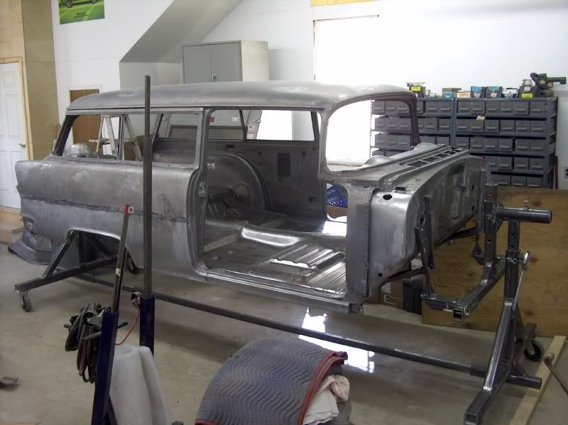
Before designing and building my own, I had looked at quite a few online, including autotwirler, roto 2000, and others. I had seen one of the "manufactured" ones up close and personal with a 57 Chevy on it, I think the steel was made of 1/8" thick tubing, which made for a less than snug fit on the pieces that slid together, enough so that the body support arms were sagging considerably. Perhaps the manner in which the car was bolted up could have contributed, but in order to not have that problem on mine, and to satisfy my **** retentive nature of overbuilding things (especially in putting someone else's vehicle on it), I made it with 1/4" thick square tubing (actually showed up as .22 wall thickness) which provided a nice snug fit. The downside to this design (besides the additional weight) is the welded seam on the inside must be removed for the pieces that slide together, unless you can find "seamless" tubing. Mine was also designed highly adjustable to allow flexibility for many different types of cars.

Some of the features I considered:

Bottle jacks....I had plans to use two engine hoists to remove the body (already had them) so I saw no need for the added expense of bottle jacks on the rotisserie to lift a car off a frame or lift the pivot to find CG. May be a "nice to have", but would have been redundant with the hoists I already had.


HPIM4783.jpg


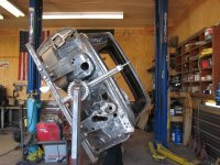
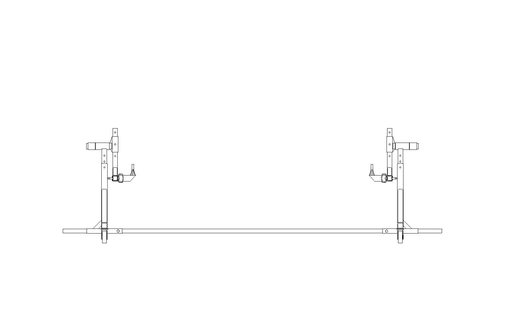
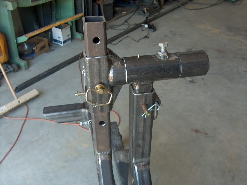
Standoffs....One feature to consider would be to weld gusseted 1/2" inside dia pipe to the support arms, as shown in the above picture, in order to "stand off" the car from the support arms and offer a virtually unobstructed area that is normally blocked by the support arm. Makes for easier sandblasting, painting , etc, without having to come back and repeat a process later.

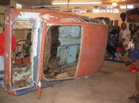
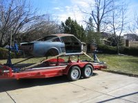
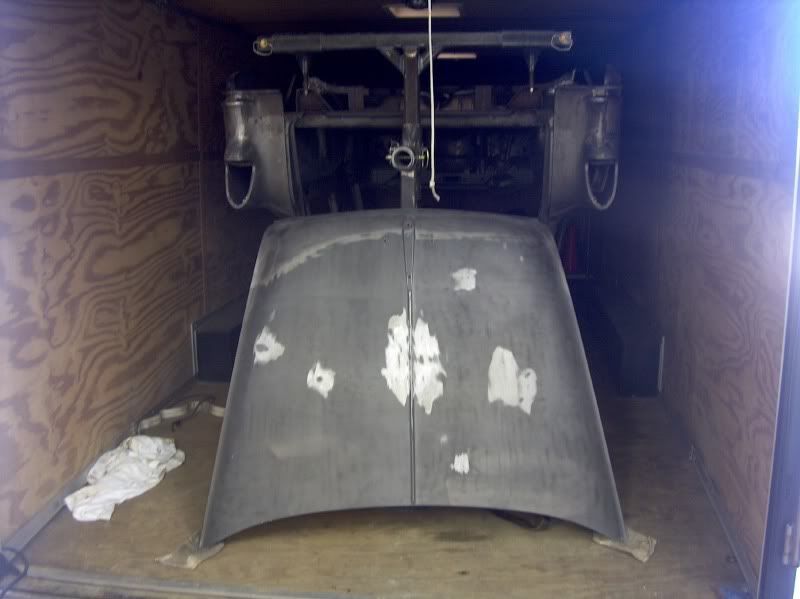
D-ring tie downs (as shown in above picture)....Another nice option so you can easily secure for transport to a media blaster. You'll get a much better job done of stripping a car if they can more readily get to everything standing up, as seen here on the return trip:

HPIM4761.jpg


For the plans:

Rotisserie1.jpg


Rotisserie2.jpg


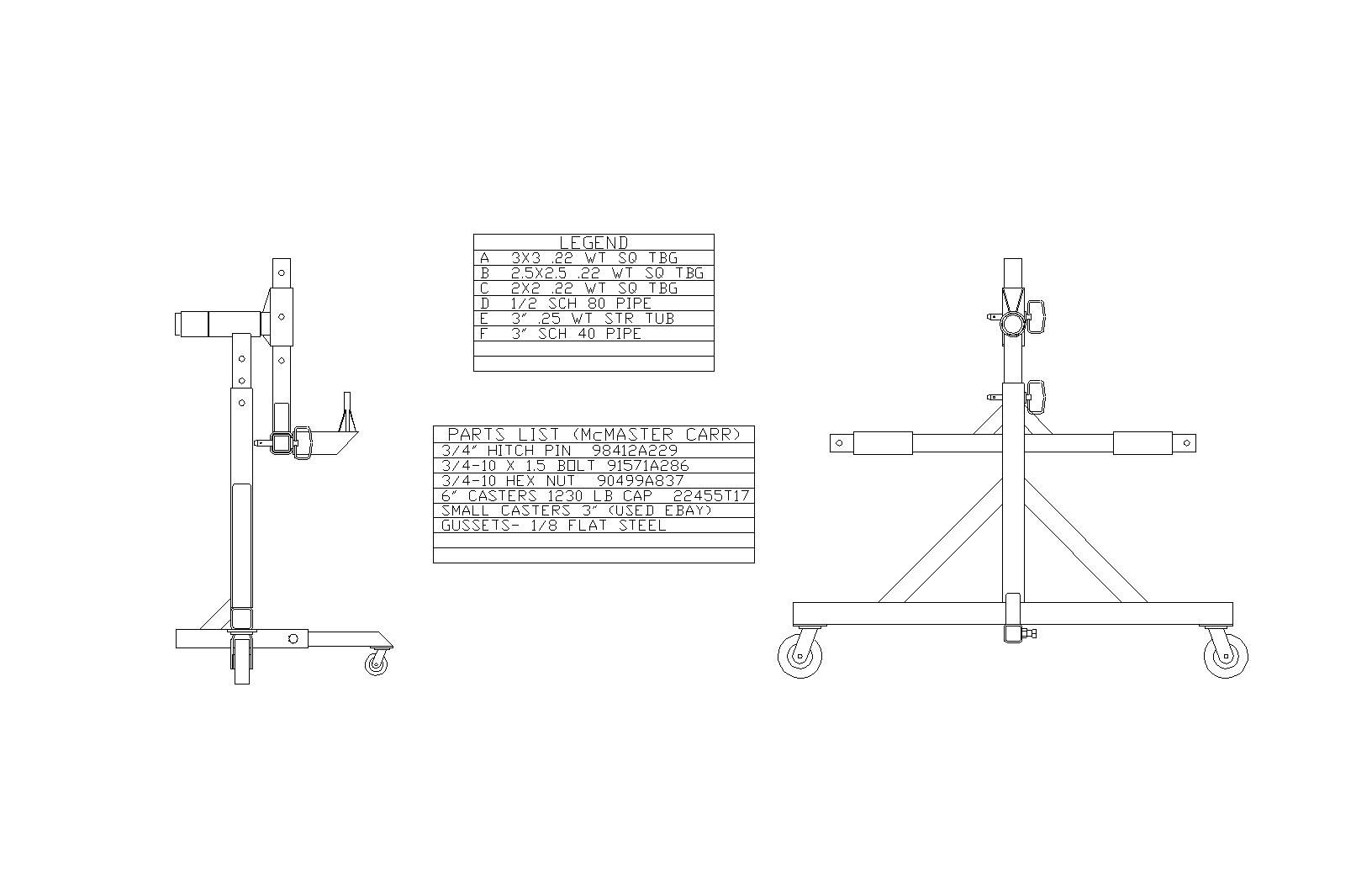
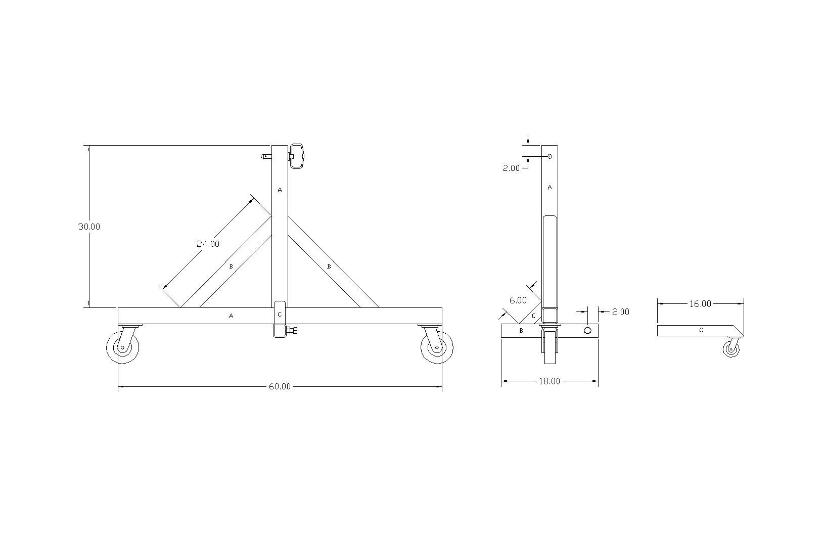
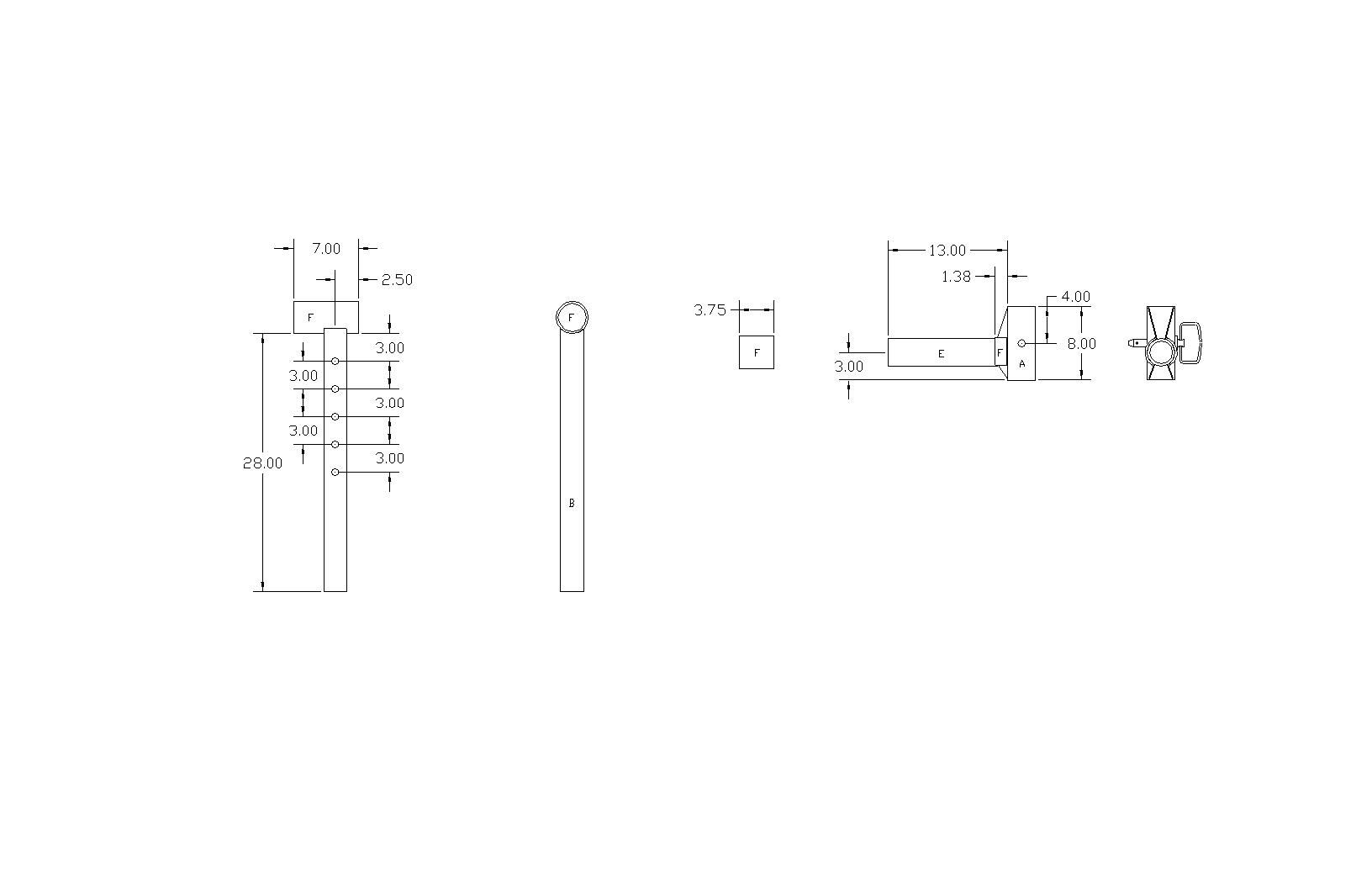
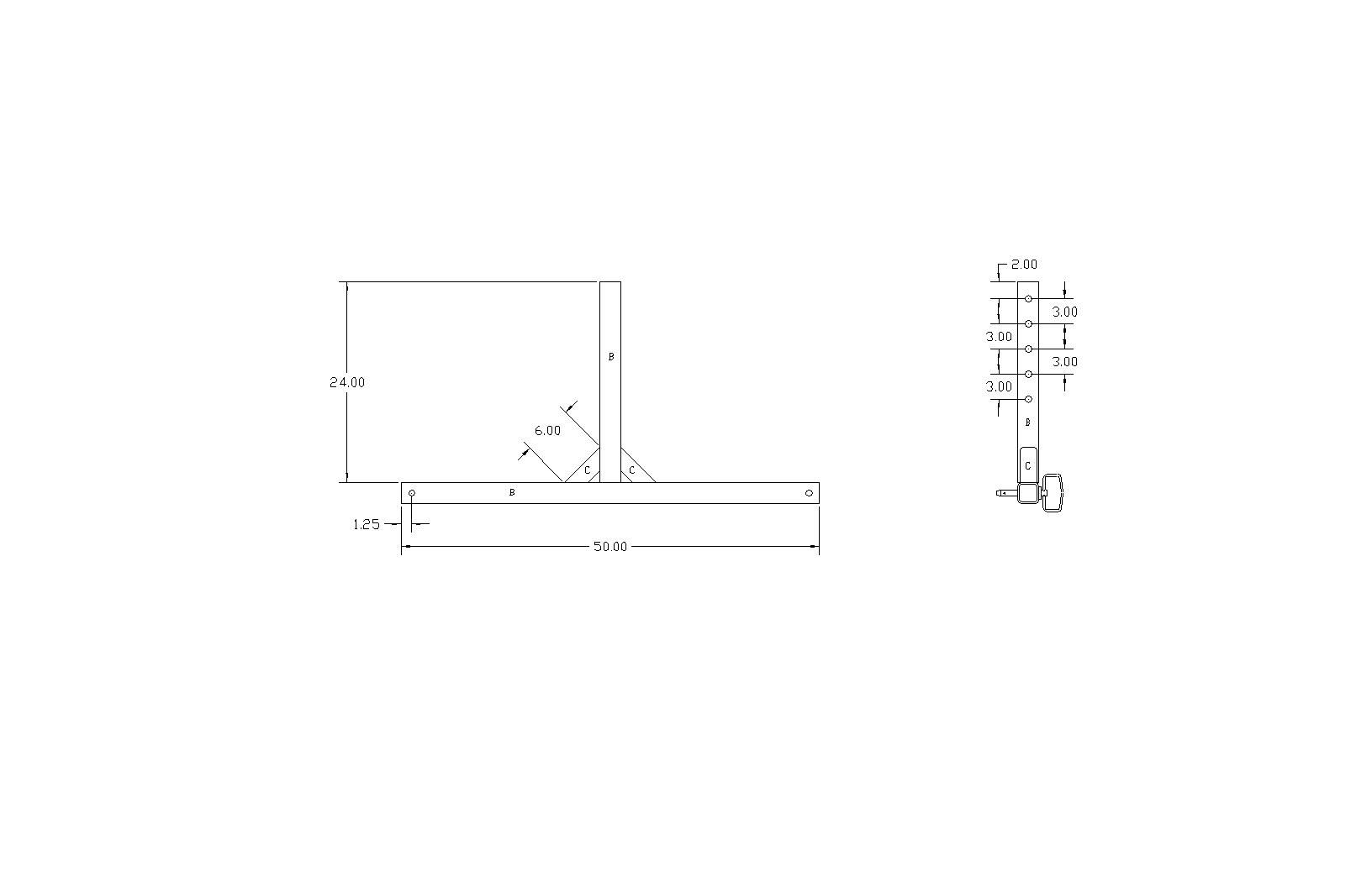
The short "third leg" caster on the right in the next picture was made to allow a partial breakdown of the pieces, and still be able to roll it around the shop without something getting away from you. With all the weight here, it does tend to take off pretty quickly.


Rotisserie3.jpg


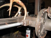
Notice in the next picture, the pivot bracket on the right, the hole for the hitch pin is offset 1" from the pivot centerline. Where the adjustments in the adjoining piece have three inch spacing between holes (following picture), this offset will allow even more fine tune adjustment for CG with a mere 180 degree rotation.


Rotisserie4.jpg


Rotisserie5.jpg


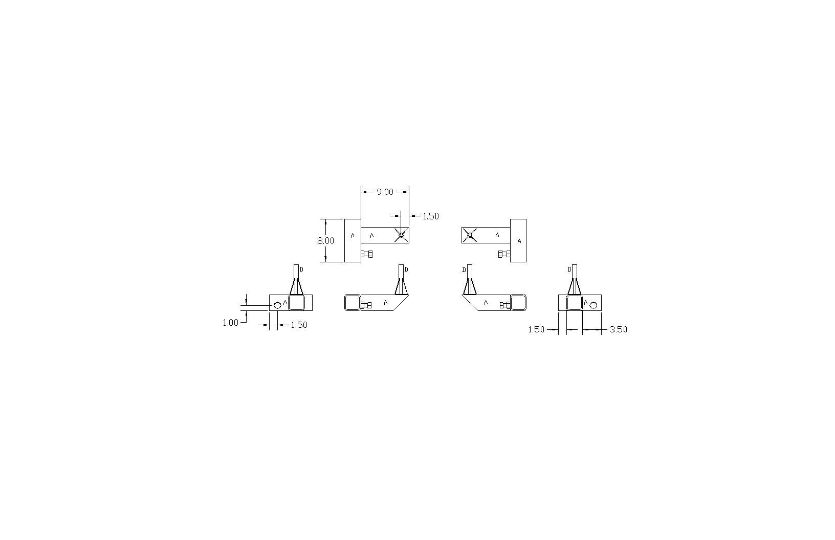
The standoffs in the next pictures did not get dimensioned as they were sized to fit some grade 8 bolts I had in stock. I believe they were about 5 or 5-1/2 inches tall, but size to the hardware you have readily available.


Rotisserie6.jpg


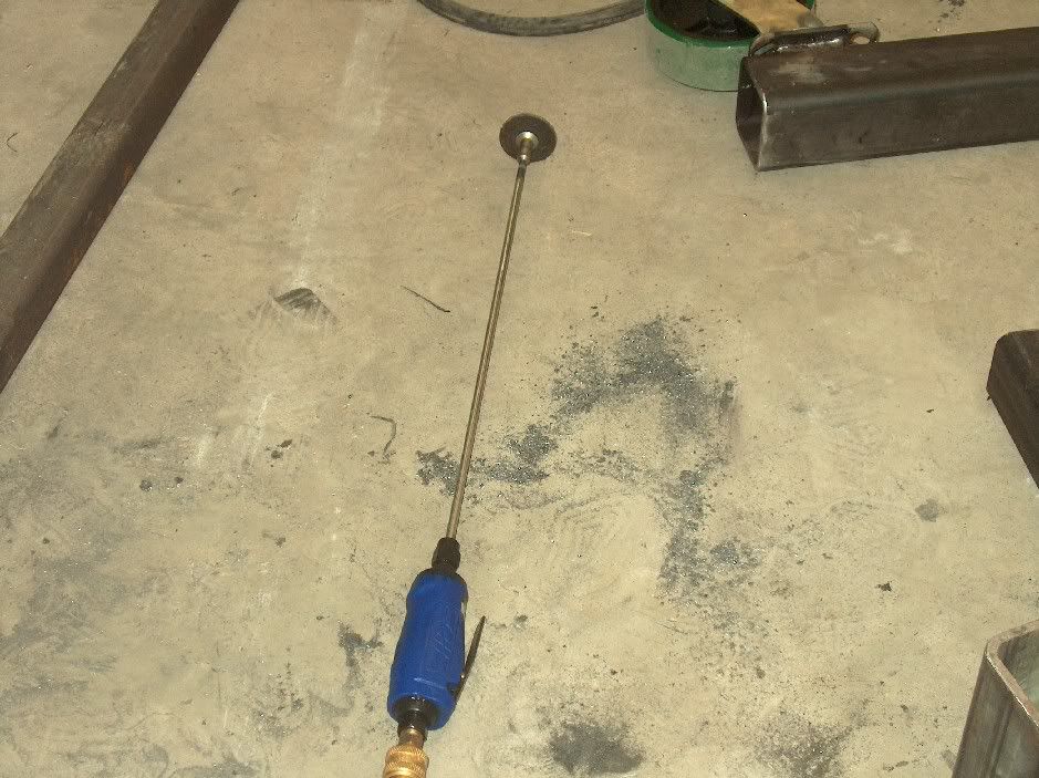
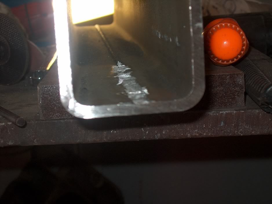
The downside to the "seamed" tubing, is that in order to slide within one another in such a "snug configuration", this weld needed to be ground smooth. In order to perform this function, a piece of .250 dia rod was welded onto a cutoff wheel arbor. I surprised myself by getting it right the first time, no wobble at all! Not shown is the auxiliary manuevering device. Basically go to your local hadware store and look for 1/4" id bearing pulleys (hint...sliding door hardware), so you can slide the pulley onto the shaft to be able to apply pressure/guidance to the cutoff wheel inside the tube. Not having this function, you hand will get warm quickly, even with gloves.


225a74ce.jpg


42c22666.jpg


The set screws were all 3/4-10 bolts, and just incase anything slips, the ends of all the "sliders" had a fail safe in a 3/4 dia hitch pin. Looking at the pivot area, it was a bit looser than I intended, so the outer pipe was sliced lengthwise and tweaked with a dead blow hammer and welded back together. For rotational stabilization, one end uses a hitch pin, with the inner tube having holes drilled at 90* increments. This will allow you to pin the rotisserie in any position in 90* increments. For any oddball angles needed, the opposite end has a 3/4-10 set screw. Also not shown on the drawings, holes were drilled and tapped for grease zserks.

4b9d0dfc.jpg


Overkill? You betcha. And with steel sold by the pound, more expensive. Would thinner walled tubing work? Sure it would. And I think strategic placement of the "setscrews" could miinimize any sagging issues on the support arms, and the steel would be much cheaper using 1/8 or 3/16 wall thickness.


I was able to dial in the CG where it will stay in any position you stop at. It also spins effortlessly using one hand once you get the CG set, so worth the extra effort.


HPIM4776.jpg


Here is a link that includes pictures and plans:

http://s5.photobucket.com/albums/y167/rmccartney/Rotisserie%20Fabrication/?start=all
 
Last edited:
To avoid these ads, REGISTER NOW!

t. jones

Well-known member
Joined
Dec 18, 2008
Messages
152
Location
Cambridge On. Canada
Great work it's nice to see Quality craftsmanship. The only suggestion I could add is I built mine with two members running length wise allowing body to scrap the ground and made it easier to work on the highside.
Thanx Trevor
 

larry4406

Well-known member
Joined
Jan 27, 2006
Messages
18,966
Location
Northern Virginia
Thank you very much for the post.

For the rotating arbor, I have been thinking on using a trailor axle from Tractor Supply. They are tube steel, with axle, bearings, and 5 lug hubs. Cutting the tube in sections gets both arbors which would spin nicely and the tube then welds to the upright. Would then need to make the arm attachments and anchor plate to bolt to the lugs.

For the angular position lock, been thinking on adapting some sort of drum brake or disk brake connected to an emergency brake mechanism. This would give any angle.

Regarding rotation and center of gravity, the arbors should always be in line while the offset (throw) of the arms should be adjustible (think rod throw on a crank). I have been trying to come up with a handwheel adjustment to tune this CG. Tractor Supply has trailor jacks that telescope and lengthen/shorten by cranking and are rated ~5000 lbs.
 
OP
M

MP&C

Well-known member
Joined
Oct 21, 2009
Messages
4,396
Location
Leonardtown, MD
Thanks for all the comments guys, I think it's good to get all these ideas out for anyone considering making their own. Where I have a 12' ceiling to work under, someone else may need the vertical clearance for lower ceilings, as Trevor suggests. I did consider using two runners, but in the end I knew I had a bunch of dress up work on floor pans to do, and wanted an unobstructed place to stand:


Picture157.jpg


Either method (single in center or two along sides) should allow easy access for spraying the inside of the car. I can tip it on the side, as shown, step through the w/s opening and paint the entire inside by standing in the side window openings. Two runners would provide the same ability there as well.


Larry, I think the wheel hubs should give you an extremely easy rotation. In my design I was looking at: 1. cheap, 2. longer horizontal support (to help prevent deflection, sagging), 3. design flexibility (if a lift cylinder was required, I could have easily shifted the pivot tubes inboard to provide a lift area for the cylinder).

They would definitely make short work of any rotation, and as you said, adjustability of the throw will fine tune your CG. I think having your CG dead nuts on is key to ease of rotation, and worth the extra effort to get it that way. The car I have shown was perfectly balanced and would stay where ever you stopped. Rotation is a one handed operation, so although I don't see a need for bearings, they would just make it all that much easier.
 
Last edited:

larry4406

Well-known member
Joined
Jan 27, 2006
Messages
18,966
Location
Northern Virginia
This information is great.

The trailor axle idea for the arbors just seemed to me an easy way to get to a rotating mechanism vs DOM tubing, lathe, etc.

Below is a picture I found on the net. Note the hand crank mechanism for a tube within a tube - this allows raising/lowering of the body so the CG can be tuned properly. I don't know how this was created, but suspect that there is a large diameter threaded rod, various nuts, etc.

Also see the disk brake.
 

Attachments

  • Crank adjuster and disc brake - eastwood forum P1.jpg
    Crank adjuster and disc brake - eastwood forum P1.jpg
    69 KB · Views: 632

OccupantRJ

Well-known member
Joined
May 15, 2009
Messages
10,918
Location
Eastern North Carolina
A worm gear winch or gearbox could be modified to drive a rotisserie axially, then a simple turn of the crank would put it right where you want it, without even having to have a locking mechanism. A step further would be a worm drive conveyor gearbox to make all electric rotation. A worm drive gear setup is self locking upon stopping of motion. As I have mentioned in other posts, an industrial salvage yard or metal scrap yard is an excellent cheap place to find things of this nature.

See http://www.directindustry.com/industrial-manufacturer/worm-gear-reducer-72868.html
 
Last edited:
OP
M

MP&C

Well-known member
Joined
Oct 21, 2009
Messages
4,396
Location
Leonardtown, MD
I think it was in the neighborhood of 600. That was using all full length new stuff, and the most eye opening price is for the casters. Even the tubing, found in drop cuts, should offer a considerable savings.
 

e-tek

Well-known member
Joined
Dec 19, 2007
Messages
10,690
Location
Saskatoon, SK
Great work it's nice to see Quality craftsmanship. The only suggestion I could add is I built mine with two members running length wise allowing body to scrap the ground and made it easier to work on the highside.
Thanx Trevor

That Is a good idea. I may have to mod mine if I put a bigger vehicle like MP&C's wagon there.

I think it was in the neighborhood of 600. That was using all full length new stuff, and the most eye opening price is for the casters. Even the tubing, found in drop cuts, should offer a considerable savings.

WOW - that's the cost of new metal! Mine was LESS THAN $300 WITH CASTERS, STEEL AND HARDWARE (plus welding wire I guess!). If you're REALLY concerned about cost though - consider the "Incredible Tip--Over Jig" (a term I coined for this marvel of wooden technology!)....it's nearly free!

It's all in my thread - as is MP&C's and a couple others.:thumbup:

http://www.garagejournal.com/forum/showthread.php?t=69042
 

4rcFed

Well-known member
Joined
Jan 22, 2011
Messages
108
Location
Pittsburgh, PA
Thanks for digging this up and bringing it to the top!!!:thumbup:


Right before we just moved........I "think" that I threw away a whole bucket of casters. I was in a whirl wind of activity trying to pack up the house, barn, and shop, that I think that I might have scrapped them. I was not thinking straight! Although, all of our stuff is still in storage, so only time will tell!
 
Last edited:

dnroe

Well-known member
Joined
Nov 4, 2010
Messages
113
Location
Easley, SC
I've been searching online looking at plans for a rotisserie to use on my camaro for about a year. Just this thread alone has more good ideas and designs in it than in all the other sites I have found online. Very nice looking designs and features guys! I plan on incorporating a mix of all these into mine. To me having a design that incorporates as much adjustment of the c.g. as possible while keeping the design as simple as possible is the key.
 

mag409

Member
Joined
Oct 7, 2007
Messages
5
Nice builds. Here are a few pics of one I built. Used some 1750Lb axle stubs and hubs for the spinner. Added a degreed ring in 15 degree increments with lock pins. One item that makes it real nice is the threaded adjusters. The top block is threaded and the lower block has a thrust bearing on it for easy turning. After mounting the car just crank it up or down until you have perfect balance.
 

Attachments

  • Rotisserie 001.jpg
    Rotisserie 001.jpg
    67.1 KB · Views: 601
  • Rotisserie 004.jpg
    Rotisserie 004.jpg
    62.9 KB · Views: 526
  • IMG_0605.jpg
    IMG_0605.jpg
    55.7 KB · Views: 523
  • IMG_0897.jpg
    IMG_0897.jpg
    147.2 KB · Views: 489
  • IMG_1007.JPG
    IMG_1007.JPG
    118.3 KB · Views: 463
  • IMG_1008.JPG
    IMG_1008.JPG
    126.3 KB · Views: 455
Last edited:
To avoid these ads, REGISTER NOW!

Brett

Member
Joined
Jan 12, 2010
Messages
20
Location
Littleton, Colorado
I didn't build my own, but I did buy a Whirly Jig several years ago. www.whirlyjig.com At the time I coudn't source the materials and justify the time spending building it for the price I paid. The thing has worked flawless. Have done several cars on it. It's paid for itself several times over.

I would suggest you all be very careful when using the center beam under the center of the car design. This design will put a lot of stress on unibody cars, convertibles, and bodys w/o frames. I've seen first hand cars come off of type jig and their body gaps are tweaked. The better design is to put load of the jig on the outside of the body (speaders). Therefore you use the rotisserie as a fixture for the car body, and not the body as the fixture for the rotisserie like the center beam design.

Also, you should never use a rotisserie for a body w/o the frame. Always use a frame under the body on the rotisserie. You can make body lift extensions so you can space the body from the frame for work access. The bare body will flex dramatically w/o the frame under it.

A few pics of my whirly jig. Note the jack stands under the body when we transported. The body was totally rested down on the jackstands and strapped down tight. This ensures the body will not unnecessarily flex during transport. i.e. hitting a bump, or bouncing around.
 

Attachments

  • blast02.jpg
    blast02.jpg
    87.5 KB · Views: 265
  • IMG_0634.jpg
    IMG_0634.jpg
    103.2 KB · Views: 268
  • IMG_0642.jpg
    IMG_0642.jpg
    131.4 KB · Views: 341
  • IMG_0639.jpg
    IMG_0639.jpg
    147.8 KB · Views: 297
OP
M

MP&C

Well-known member
Joined
Oct 21, 2009
Messages
4,396
Location
Leonardtown, MD
Boy, that sounds like a testimonial right from their website, complete with the link. How much comission do you get? :bounce:

I'll have to admit, your post would apply to most of the rotisseries out there, both home-made and store bought. But as this thread was started for my rotisserie fabrication, (at the request of other members who saw it) I'll have to conclude your comments are referring to my rotisserie.

Before I decided to build my own, I looked at quite a few and didn't like what I saw because they did not meet my standards. Yes, mine is overbuilt, 1/4" wall thickness where most others use thinner. But what I built gives me the peace of mind to transport a vehicle on the rotisserie, bumps and all. (4 bolts, yes, upside-down) It was 1-1/2 hour drive to and from the media blaster, just as you see it:


HPIM4761.jpg


I have tie down rings on it as it was purpose built to use it in this fashion. If your Whirlyjig, having the better design of putting the load of the jig on the outside of the body (speaders), is such an engineering marvel, why the need for jackstands? No faith? The simple fact of the matter is that set up is critical, and that regardless of whether one or two crossbars, stresses are introduced if set up is not done properly.
 
Last edited:

Brett

Member
Joined
Jan 12, 2010
Messages
20
Location
Littleton, Colorado
Boy, that sounds like a testimonial right from their website, complete with the link. How much comission do you get? :bounce:

I'll have to admit, your post would apply to most of the rotisseries out there, both home-made and store bought. But as this thread was started for my rotisserie fabrication, (at the request of other members who saw it) I'll have conclude your comments are referring to my rotisserie.

Before I decided to build my own, I looked at quite a few and didn't like what I saw because they did not meet my standards. Yes, mine is overbuilt, 1/4" wall thickness where most others use thinner. But what I built gives me the peace of mind to transport a vehicle on the rotisserie, bumps and all. (4 bolts, yes, upside-down) It was 1-1/2 hour drive to and from the media blaster, just as you see it:


I have tie down rings on it as it was purpose built to use it in this fashion. If your Whirlyjig, having the better design of putting the load of the jig on the outside of the body (speaders), is such an engineering marvel, why the need for jackstands? No faith? Or not recommended in the brochure.....


No comission here :) Just purchased and received a great product that has never left me down and has performed very well for the past several years I've owned it. (How often does that happen these days?) It's been used on several car projects from media blasting to complete structural rust repair.

Before I bought one, I too looked at many manufactures, DIY jobs, and talked to people that owned them. I too was not impressed with what I was seeing. I even drew a design up in CAD, spec'd out a materials sheet, and went shopping for materials. I concluded that I would spend more time and money building one, than buying one.

Conclude what you will. Just speaking from personal experience and knowledge on the rotisserie design with the beam down the middle. That design tweaked the unibody on another car I did. Sure the car came out nice, but the body gaps in the doors and fenders were definately affected after is spent some time on it. I also have a friend that did the body of his Olds off of the frame and on a rotisserie...and guess what his door gap alignment is off.

When I transported the car, it's not that I didn't have faith in the rotisserie, it is just a prefeference on safety and common sense. Notice it was on an open flatbed trailer, not in an enclosed trailer. I locked the jig down as low as it would go and strapped the body down. I suppose I could have hung it upside down to get the same effect.
 
OP
M

MP&C

Well-known member
Joined
Oct 21, 2009
Messages
4,396
Location
Leonardtown, MD
Just purchased and received a great product that has never left me down and has performed very well for the past several years I've owned it. (How often does that happen these days?)

That is true. And to be up front, I'm not saying that Whirlyjig has a bad product, far from it. Just trying to learn more about the one you did use that caused damage to the cars... This thread was started for the benefit of members wishing to build their own rotisserie, not buy one. But that's not to say we can't learn from one. If the WJ has benefits, let's hear them so the guys building their own can make an informed decision on what features they may want to include in their own design.

Because someone uses a center beam rotisserie and it tweaks a car body doesn't mean all center beam designs are bad. How many guys out there do you think have used a center beam design with success? Surely not all of the center beam designs have resulted in a substandard outcome.

A rusted out car that won't support what's left of the floor pans from lower rot is hardly a candidate for installing on a rotisserie without careful consideration for where and how much bracing should be installed. But I'm sure that some one out there has done so, with drastic results. So even more important than the benefits of the WJ, if you could discuss the parameters surrounding the unsatisfactory results you experienced, it would hopefully help other members from having similar results.

Rotisserie:
Was this a home-made rotisserie or company manufactured?
Got any pictures of your car on that rotisserie?
What was the material thicknesses?
Any slop in the fitment of the body attachment arms?
Was the center beam one continuous piece or multiple slid together with setscrews?
Was center beam of thick enough material to resist deflection?

Set up:
What kind of bracing was used, was it installed properly?
Were the end truss supports installed plumb so as not to induce stresses?
Or was set up done by your body guy (in unknown/questionable fashion)?


Brett, I built mine with a single center beam for a reason, so I don't have obstructions when working on the car, without having to remove a component of the Rotisserie. Others I have talked to used the two beam design because they have low ceilings to contend with, and wanted a spread there for clearance in the car rotation while set at a lower height. Hardly a concern with my 12' ceilings, it was more important to me to be able to stand firmly on the floor while using grinders, sanders, etc, without tripping over a crossbeam. I use cherry pickers to load the car, so I didn't need the added expense of lift cylinders or screw jack adjusters, although the adjusters would be nice. I have enough adjustment in CG to set it up where the car will stop anywhere I rotate it to, without trying to reposition itself, and I can rotate it effortlessly with one finger. And with 1/4 thickness even on the cross beam, it doesn't flop around/deflect that would cause any variance in the width between the end support trusses. At the time, I didn't have $1200+ that they were getting for "storebought" versions, so I built my own at about half that price. But excluding optional features I don't have, mine is well built enough to stack up against any rotisserie out there, two beam or otherwise. I can understand a guy (myself included) gets a tainted image of a product from a negative experience. But venturing a guess, I would say your results stemmed from your body guy having issue with an improper set up, improper bracing, or the guy had a cheaply made rotisserie (sloppy fit). I'd be curious to know what the actual cause of the issue was. To me on a well-built rotisserie, the one or two beam design is a user preference as I described above, with no ill-effects either way.
 
Last edited:

Brett

Member
Joined
Jan 12, 2010
Messages
20
Location
Littleton, Colorado
I do not have pictures of the car on the rotisserie. This was almost 20 years ago, before digital cameras. The film I had of the car at this phase was stolen. I had at least 10 rolls of film. Gave them to my mother to drop off to be be processed, her purse was stolen and never found. I still own the car.

That jig was most likely a DIY job and not a particular manufacture. I don't know much details on it. It's long gone. But I do remember that it was built rather sturdy and guy mainly used it for corvettes. The floors in this mustang were replaced one side at a time, which helped maintain the structure but I feel still contributed to the door gap issues. Also, back then cars were really shot and put back together assuming they would go together like they were taken apart. Technology and techniques have changed since then. Cars are now body worked together, fitted, torn down, painted, and reassembled.

Attached are some pics of the door gaps on the blue car. It's hard to pick up in a picture. There is a side by side shot of the blue car with an unrestored white car. Both are 65's. The white car's body gaps are amazing even for an old mustang. Before the blue car was painted, the gaps were pretty good. I had a real b!$%h of a time reassembling the car and getting the gaps somewhat right. They are the best they can get w/o doing the car over again. But they were definately better before the car was disassembled and painted.

If you notice on one of the pics my above post, the WJ is setup with the outside pipes removed. When I've had the jig setup working on a car, I've never put the outside pipes in, except only to move it. Here's the reason and logic behind that. The jig sits flat on the concrete shop floor. The load on the jig fixture is never really on the fixture, but instead spread onto the floor. Effectively, the floor becomes part of the entire jig fixture, thereby creating a very rigid design. The body is relieved of stress, and is effectively is resting on the floor. When the jig sits flat on the floor, there is more much more contact area, and the psi is spread over a much larger surface area.

With a rotisserie with the center beam and wheels on 4 corners, the load is always going to be on the fixture itself. The contact area of 4 wheels on the floor is very minimal, therfore the psi load pressure is always going to be on the center beam and jig itself, which has far less surface area. Every jig I've ever seen in this design has always had a "spring" feel to it. That is because steel by molecular nature will flex and tend to spring back into memory. This is especially true over long spans. A jig with wheels on each corner, sitting several inches off of the floor, and the center beam installed can still be flexed w/o a body on it. At 200lbs, I can stand in the middle of this type of fixture, and still have a measurable amount of deflection in the center beam. The wheels become a pivot point for weight in the middle of the center beam. Sure you can build in more rigidity into the structure with thicker materials, triangles, cylinders, etc. to minimize the deflection. Now, by putting something to support the jig in the middle of the center beam will deflect that load into the floor. Getting rid of the wheels on each corner and resting the jig on the floor will definately make all the difference in any deflection.

Your material selection and construction has increased the load capacity of the jig. The wagon in the pictures has a very rigid structure, compared to most vehicles. You will probably never see an issue. A lot of other cars w/o frames under them would have issues. Imagine what would happen to something like an early bronco tub w/o the support of the frame.

I hope other GJ readers will benefit in this discussion. There are a ton of ways to do the same thing here. Some jigs are better than others. Is yours good and well built. You bet. Is mine good and well built. You bet. Are there bad examples out there? You bet. :beer:

Regards,
Brett
 

Attachments

  • IMG_2803.JPG
    IMG_2803.JPG
    66.7 KB · Views: 138
  • IMG_2805.JPG
    IMG_2805.JPG
    42.9 KB · Views: 136
  • IMG_2806.JPG
    IMG_2806.JPG
    41.4 KB · Views: 151
OP
M

MP&C

Well-known member
Joined
Oct 21, 2009
Messages
4,396
Location
Leonardtown, MD
Did your body guy have the doors installed while on the rotisserie before welding the floors etc. in place? I think some of that door gap issue could have been resolved prior to welding panels in if only the doors were on to verify gaps. Looks like the bottom of the door opening was closed up somewhat to cause the gap tighter at the bottom. Come assembly time, given what you were faced, it's trying to find a happy medium at that point. I'm wondering if a fixture could have been made to bolt to the upper hinge area of the A pillar to do some slight pulling to close that gap some, without damaging the paint.

I do remember that it was built rather sturdy and guy mainly used it for corvettes.

There's your answer right there. Those door gaps look exactly like ones on the older Vettes. A perfect example why you can't take a Mustang to a Corvette guy. You didn't use that body guy again, did you? :lol_hitti


At 200lbs, I can stand in the middle of this type of fixture, and still have a measurable amount of deflection in the center beam.

I think you'll be able to do that on any beam that spans upwards of 20', even the ones you have there on yours, given enough clearance. But I'll be honest, I don't have a 200 pound guy bouncing on my center beam with a car on there, and the center beam doesn't deflect any when I rotate the car. I think you've read too much of their propaganda and all the negative speak on their website of everyone else's products. :headscrat
 

Brett

Member
Joined
Jan 12, 2010
Messages
20
Location
Littleton, Colorado
Robert,
I'm really offering advice here for other GJ members. Rather than focusing on my previous misfortune and knocking the body guy look at the design of the jigs. I think you have failed to read the simple engineering explanation I gave behind the different designs in the previous post. It's not a conspiricy. It's simple structural engineering 101. The more surface area you can contact, the more the load is distributed.

Look at the other pic's in this thead. You don't have to go far looking for examples. The camaro on the jig is sitting flat on the concrete. The fairlane has 2 additional wheels for support under the center beam. My jig sits flat on the concrete. Effectively what each one of these examples has done is tranferred the load of the jig into the floor.

You jig may be sturdy. Good for you for building it yourself. A lot of pride goes that. There is still a visable bow in the center beam on one of your pictures in the first post. The entire weight of anything that goes on that jig is on that center beam. The contact with the floor is on 4 castors. There is no support under the middle. The load bearing weight is entirely on that center beam. With one minor simple change to your design, the characteristics of the jig entirely change. Support the center beam or ditch the wheels on the corners.

Good luck with the project.

Regards,
Brett
 

e-tek

Well-known member
Joined
Dec 19, 2007
Messages
10,690
Location
Saskatoon, SK
I'm no engineer (I just play one on GJ like everyone else!), but this is how I see it:

Regardless of whether a rotisserie has one beam or two, 2 wheels or 6..... the body (without a frame) is suspended from the front and rear ends - correct? Accounting for nominal differences in stability of the outer ends due to having more wheels/bracing, this suspension is going to have a very similar effect on the car - which is to cause stress/deflection right through it: stretch on bottom, compression on top.
Judging by the lack of people complaining about the issue you brought up, that of frameless body's getting tweaked on rotisseries, I'm guessing it's pretty-much a non-issue, when the car is either (a) structurally strong enough (through the inner sills, roof structure and floors/rockers, or (b) braced properly if not.
Of course on any frameless structure - if you suspend it from either end and then cut enough of the strength out of it, then it's going to bend. Take both inner and outer rockers out of a convertible suspended like that and it'll fold like a lawn chair!
Over the years, I've worked on, read about and seen MANY cars on rotisseries - as I'm sure Robert has - and I've never seen this issue brought up as a major concern. Can it happen - given a weak enoughbody, I would think it could. Is one vs. two beams accross the bottom going to make any appreciable difference - I don't think so. I certainly won't be losing any sleep over it.
:beer:
 

PeteMoore

Well-known member
Joined
Jan 25, 2011
Messages
453
Location
N.Ireland
Thank you for this thread

I have a spit made for the Midgets, but it was thrown together and I am wanting to "improve it"

The main problem with midgets is that they do buckle should you remove either of the sills (rockers in your language) or the ****** tunnel, both of which are quite likely considering how much they rot.

My intentions are to build in a brace/frame jig that the inner chassis legs can rest against and be clamped to, hopefully stopping any buckling in the frame whilst the sills and floors are removed.

We also tend to weld braces into the door shuts when doing so, i currently have a couple of braces which i can adjust on threads to open or close the door gap to suit my needs. Makes life so much easier when doing sills.

My intention is to remake the braces so they bolt in, preventing destruction of original interior pieces and thus meaning less to remove prior to commencing the job.

Once i get the workshop back to a standard of running I will post pics of my progress, but thank you for your pics and time on this thread, it has given me ideas of just how i should go about doing it.

Pete
 
OP
M

MP&C

Well-known member
Joined
Oct 21, 2009
Messages
4,396
Location
Leonardtown, MD
.......Accounting for nominal differences in stability of the outer ends due to having more wheels/bracing, this suspension is going to have a very similar effect on the car - which is to cause stress/deflection right through it: stretch on bottom, compression on top.
Judging by the lack of people complaining about the issue you brought up, that of frameless body's getting tweaked on rotisseries, I'm guessing it's pretty-much a non-issue, when the car is either (a) structurally strong enough (through the inner sills, roof structure and floors/rockers, or (b) braced properly if not.
Of course on any frameless structure - if you suspend it from either end and then cut enough of the strength out of it, then it's going to bend. Take both inner and outer rockers out of a convertible suspended like that and it'll fold like a lawn chair!

Bingo! I'd venture to say you cut enough structure out of a car on even the WJ, without proper bracing you'll have issues. It's why they want you to keep the car on it's frame, because even their product is not impervious to those lacking common sense.


Robert,
I'm really offering advice here for other GJ members. Rather than focusing on my previous misfortune and knocking the body guy look at the design of the jigs. I think you have failed to read the simple engineering explanation I gave behind the different designs in the previous post. It's not a conspiricy. It's simple structural engineering 101. The more surface area you can contact, the more the load is distributed.

Brett, yes, I hear you on the engineering explanation. And I know you have forgotten many details of the Mustang build other than it was a center beam rotisserie. The point I was trying to make is you don't mount a unibody car/deframed body/weakened body from structural rust issues on a rotisserie and remove structural members without expecting some consequences, unless provisions are taken to prevent structural damage/movement. Be that the addition of temporary bracing or through the use of a rotisserie design like you have now. So yes, I still go back to your body man and say he should have braced the body more sufficiently before undertaking what he did, given what he had to work with at the time. 20 years ago, in the absence of your Whirly Jig, some good old common sense would have prevented your misfortune. I apologize for the Corvette humor, had you worked on one in the past, you would have gotten the reference. I did not intend to pick on him or your misfortune, but someone out there is likely using a similar rotisserie as he did, and perhaps they can't afford the 1K plus to replace what they have with a Whirly Jig. It was here that I thought some input from you would be invaluable to indicate that perhaps had he/you installed temporary braces across the door openings prior to installation on the rotisserie/removal of rocker panels (for example) that the circumstances could have been avoided. One of those "if we had only done this...given what we had to work with...." Information such as this would help out someone to prevent a similar outcome, without the expense of replacing a rotisserie they may already have. I think it's great that you have your own rotisserie now that through it's design will help prevent a reoccurance of your misfortune, but also think that some circumstances will still require bracing/external support depending on the process.

In the case of the wagon I'm working on, the floor pans, crossmembers, inner and outer rockers have all been replaced, sitting on the frame. Made sense to me to leave it on a stable base, so that holes would align to what they needed to bolt to, and to prevent any incident of structural failure/compromise. It was only relocated to the rotisserie once completed, for some cleanup work. I actually built it as a painting fixture initally, not for installing structural panels. But given the accessibility limitations, one needs to plan accordingly and really look at the order in which the panels are installed to work around those limitations. I can also see where the rotisserie would be invaluable in working on a unibody car, but again, I would plan accordingly, and install bracing as required or perhaps install two beams as a frame for supporting the car during removal/replacement of structural members, as conditions dictate. Although the wagon body is back on the frame now, it will go back on the rotisserie in a couple months for the painting. At that time, I'll be sure to get some dimensions for you so we can see how much if any deflection occurs with weight applied.
 
Last edited:

69supercj

Well-known member
Joined
Jan 26, 2010
Messages
555
You can always build a support that bolts into the door hinge area and the nader pin if your doors are off the car. These are supposed to add lots of rigidity to the bare body.
 

milkovich

Well-known member
Joined
Oct 15, 2007
Messages
677
Location
Akron Ohio
Seems like if you built a strut that went above the car to prevent the two verticals from deflecting, it'd still be out of the way. It wouldn't really have to be thick either.
 

Finnrodder

Member
Joined
Dec 28, 2012
Messages
17
Location
Finland
You did a good job with your rotisserie,i think i use some of your ideas with my rotisserie.Thanks for sharing this!
 

CARS

Well-known member
Joined
Jan 19, 2011
Messages
535
Location
New Ulm, MN
Robert, it looks like your jacks are for adjusting the center of gravity.
My Roto 2000 jacks are for adjusting height AFTER center of gravity is found and set.

What was your thought process to do it this way?
 
OP
M

MP&C

Well-known member
Joined
Oct 21, 2009
Messages
4,396
Location
Leonardtown, MD
Chris...mine does not have jacks, the one pictured in post 6 is not mine. I have two cherry pickers so decided to just use those. There are a couple guys in Australia that used my plans and added cylinders. Getting ready to leave for work but I'll add a link to that build this evening..
 

larry4406

Well-known member
Joined
Jan 27, 2006
Messages
18,966
Location
Northern Virginia
I posted pictures of my rotisserie in the weld fab thread. Hydraulic cylinders for lifting, hitch pins in drilled holes to ensure concentric axis of rotation, center of gravity adjustment lead screws, and position locks.
 

gus1962

Well-known member
Joined
Dec 21, 2012
Messages
382
Location
Canton, Ohio
Wow, very well thought out and nicely executed! Love browsing onto details and I am looking forward to seeing the final product.
 
To avoid these ads, REGISTER NOW!
Top Bottom