To avoid these ads, REGISTER NOW!

100 amp service to shop

Mouse4x4

Member
Joined
Jul 19, 2019
Messages
14
Location
ESMD
So I have roughly a 450' run from my house to the new shop. I have ore wired the shop to accept 100amp service and that is what I plan to run from the house out. I know this is not the best method but it is the only one I am considering and just looking to accomplish it the best way. So here is my plan and I am looking for ideas of wire size.

I plan to run copper from my breaker panel in the house from the 100amp breaker to a disconnect box or junction box of some sort on the outside of the house maybe a 15' at most run of wire. I want to use copper here to make it the biggest size possible that will accept connection in the breaker and make it easier to work with.

Then I will run the larger size aluminum wire from the disconnect/junction box from outside if the house all the way to the shop and I to the panel.

Yes no Indifferent? Tell me your thought. This is not a production shop or a full time shop it is a hobby shop and boat storage, wood stove heat, air compressor and a occasional welder running here and there. Right now I have a 110 drop cord ran the full distance to the shop for lights radio and outlets and all had been fine. But I want to finish this up and have it done.
 
To avoid these ads, REGISTER NOW!
OP
M

Mouse4x4

Member
Joined
Jul 19, 2019
Messages
14
Location
ESMD
Another question, does voltage drop only occur at max amps? Or is it across the whole spectrum
 

mike93lx

ALLIANCE MEMBER
Joined
Dec 9, 2013
Messages
37,974
Location
Richmond, VA
According to southwire, you are looking at 350MCM. 4/0 if you are OK with 4.4% VD. Keep in mind you likely won't ever hit that level, so I would be fine with it in my shop.

That is going to be expensive and some large conduit

I would really think about usage and come up with a reasonable current demand, if you care about the cost. If you don't, send it!
 
Last edited:

Fasthotrod

Well-known member
Joined
Dec 14, 2015
Messages
218
Location
Oklahoma
Another question, does voltage drop only occur at max amps? Or is it across the whole spectrum

It's load dependent. If you were to connect the wiring and then just hook up a meter, you'd read nominal voltage. (120/240 VAC)

As you start to add load, the wiring begins to heat up and along with that comes increased resistance along the length of the wire. The more current, the more heat, and the more resistance... which is what causes the voltage drop.

Your plan sounds decent to me... using copper from a 100A breaker in the panel and out to a junction box with some terminal blocks to accept the change from copper to aluminum works. You could also go into a fused disconnect, but that's likely a bit more money.

You'll want to size the junction box based on the conduits in/out of the box and the required distances between them. The NEC is pretty specific about that part. More info here:

https://www.ecmweb.com/national-electrical-code/code-basics/article/20892904/sizing-junction-boxes

Hope this helps.

Mark
 
OP
M

Mouse4x4

Member
Joined
Jul 19, 2019
Messages
14
Location
ESMD
This is all going to be direct burial wire. Likely just go with mobile home direct burial. I get so confused because of have asked 3 different electricians and gotten 3 different answers now plus what I have gotten on here. One has told me that 1/0 is what I need and then another said 2/0 will be just fine also and will connect directly to the breaker. Then another telling me copper all the way is the only way. Eyiyi craziness
 

brewchief

Well-known member
Joined
Sep 20, 2008
Messages
2,371
Location
Michigan
This is a case that it might make sense to look at URD as well as MHF, the URD can't go inside at all so it would need junction boxes at both ends but with the length needed the cheaper cost might make sense.

Sent from my SM-G965U using Tapatalk
 

mike93lx

ALLIANCE MEMBER
Joined
Dec 9, 2013
Messages
37,974
Location
Richmond, VA
This is all going to be direct burial wire. Likely just go with mobile home direct burial. I get so confused because of have asked 3 different electricians and gotten 3 different answers now plus what I have gotten on here. One has told me that 1/0 is what I need and then another said 2/0 will be just fine also and will connect directly to the breaker. Then another telling me copper all the way is the only way. Eyiyi craziness

2/0 would be fine for most shops. But you want something more than what most need.

The calcs are simple and readily available online.

A couple basic points, you need a 4 wire feed and 2 ground rods at the shop.

I would run this wire: https://www.wireandcableyourway.com/4-0-4-0-4-0-2-0-aluminum-mobile-home-feeder-cable.html
 
OP
M

Mouse4x4

Member
Joined
Jul 19, 2019
Messages
14
Location
ESMD
Found my other thread I started and read some of this eresponses. May just drop down to 80 amp and go from there. Instead of fully taxing everything to the max now.
 

wyliesdiesels

Well-known member
Joined
Aug 14, 2012
Messages
20,089
Location
Modesto, CA
Instead of relying on others and calculators with errors (the southwire calc being one of them) why not do the calcs yourself?

I posted the formulas on the electrical FAQ sticky
 
Last edited:

Alchymist

Well-known member
Joined
Mar 1, 2009
Messages
4,423
Location
Central PA
It's load dependent. If you were to connect the wiring and then just hook up a meter, you'd read nominal voltage. (120/240 VAC)

As you start to add load, the wiring begins to heat up and along with that comes increased resistance along the length of the wire. The more current, the more heat, and the more resistance... which is what causes the voltage drop.

Your plan sounds decent to me... using copper from a 100A breaker in the panel and out to a junction box with some terminal blocks to accept the change from copper to aluminum works. You could also go into a fused disconnect, but that's likely a bit more money.

You'll want to size the junction box based on the conduits in/out of the box and the required distances between them. The NEC is pretty specific about that part. More info here:

https://www.ecmweb.com/national-electrical-code/code-basics/article/20892904/sizing-junction-boxes

Hope this helps.

Mark
Not quite - the resistance of the wire is fixed - the voltage drop is a function of current. (E=IxR)
 
To avoid these ads, REGISTER NOW!

Fasthotrod

Well-known member
Joined
Dec 14, 2015
Messages
218
Location
Oklahoma
Not quite - the resistance of the wire is fixed - the voltage drop is a function of current. (E=IxR)

You're right... the resistance if fixed if we assume no temperature change. The conductor resistance is the determining factor for the distance/voltage drop calculation, no doubt. My bad.

But it's not correct to say that it's fixed, either. The conductivity of copper changes with temperature, as does other conductors such as aluminum. So to say that the resistance is fixed is not entirely true. (It's also not as bad as one might assume.)

So for example, if we used 100A as the current and assumed a 00 copper conductor that has a fixed resistance of 0.078 ohms per 1000 ft at 20C:

E = I * R
E = 100 * 0.078
E = 7.8 volts @ 1000 ft

So for a 450 ft run, or 45% of the initial resistance: Approximately 3.51 volts. If we stop there, it's close enough.

If we calculate the power loss: 3.51 volts * 100A = 351 watts. Where is that going? It's heat loss. How much would that increase the temperature of the conductors? No idea... I'm sure there is a thermodynamics equation that would tell us, but I don't recall it from school.

As I was saying, temperature has an impact on the conductivity of the material, be it copper, aluminum, etc...

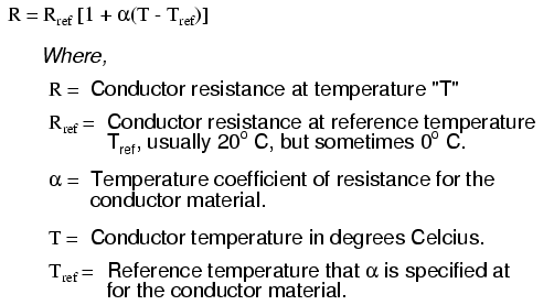
10226.png


Copper has a temperature coefficient of 0.00393 so if we're talking about a conductor rated at 70C and assuming that we see that temperature:

R = Rref [1 + a (T - Tref)]
R = 0.078 ohms [ 1 + 0.00393 (70 - 20)]
R = 0.078 ohms [ 1 + 0.00393 * 50)]
R = 0.078 ohms [1.1965]
R = 0.093327

What's that, about a 16% increase in resistance?

So back to the original math:

E = I * R
E = 100 * 0.093327
E = 9.33 volts
450' run would be 4.199 volts, or 419.9 watts lost to heating of the conductors.

Is the difference much to worry about? Not in a residential application. Mouse4x4 will likely never see that type of drop anyway, as I doubt he's going to be running fully loaded.

Thanks for the sanity check. :beer:

References:

https://www.allaboutcircuits.com/textbook/direct-current/chpt-12/temperature-coefficient-resistance/

http://hyperphysics.phy-astr.gsu.edu/hbase/electric/restmp.html
 

Norcal

Well-known member
Joined
Mar 16, 2008
Messages
13,770
The one thing everyone forgets is the feeder will rarely, if ever, be fully loaded.
 
OP
M

Mouse4x4

Member
Joined
Jul 19, 2019
Messages
14
Location
ESMD
Thanks fellas for all the info, and appreciate all the help. Like others have said it will prolly never see full load and never experience the voltage drop and if it does I will shut something off and reset the breaker and roll with it.
 
OP
M

Mouse4x4

Member
Joined
Jul 19, 2019
Messages
14
Location
ESMD
Mobile home wire seems to be about the best deal around for direct burial, so here comes the next question I notice most are sized with the hot legs of same size then the neutral a bit smaller and ground even smaller. Is that all good for the shop wiring?
 

mike93lx

ALLIANCE MEMBER
Joined
Dec 9, 2013
Messages
37,974
Location
Richmond, VA
Since you are up sizing due to voltage drop, you may need to go with the larger EGC.

A sparky may be able to confirm for sure.
 
OP
M

Mouse4x4

Member
Joined
Jul 19, 2019
Messages
14
Location
ESMD
So pulled the trigger and went with a 4/0-4/0-2/0-4 mobile home feeder of 500' disconnect on out side of house and go with 1/0 from disconnect to breaker in main panel of house 5-6' or so. Let the Sparks fly
 

Bert_

Well-known member
Joined
Dec 24, 2016
Messages
9,788
Location
NW Iowa
So pulled the trigger and went with a 4/0-4/0-2/0-4 mobile home feeder of 500' disconnect on out side of house and go with 1/0 from disconnect to breaker in main panel of house 5-6' or so. Let the Sparks fly

The #4 ground is to small in your case. Since you upsized the current carrying conductors you must also upsize the ground in proportion. I didn't do the math but I'm guessing you should have had a 1 or 1/0 ground.
 

Bert_

Well-known member
Joined
Dec 24, 2016
Messages
9,788
Location
NW Iowa
I did the math and you required to have a #2 aluminum ground.

Just order a #2 USE single conductor. Throw it in the trench with the other wire.
 
Last edited:

pattenp

Well-known member
Joined
Jun 4, 2008
Messages
10,175
Location
Virginia - USA
USE only can't enter structure. It needs to RHH/RHW/USE. Unless terminated outside of shop too.
 
Last edited:
OP
M

Mouse4x4

Member
Joined
Jul 19, 2019
Messages
14
Location
ESMD
Boy oh boy I feel retarded as ****, so like they always say if you need it done right do it yourself. My distance to the shop from the house is no where near 450-500' it is only 235'. That makes a huge difference in things correct? So back to the drawing board for wire size I guess. Anyone want to set me straight now for 100 amp for a 250' run of wire what size is needed?
 
Last edited:
To avoid these ads, REGISTER NOW!
Top Bottom