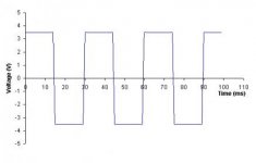
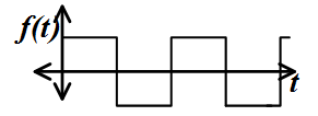
My interpretation matches up EXACTLY with the "rest of the electrical world". When the voltage "crosses" the 0v threshold and goes negative, it's changing polarity or "alternating".
This is an AC waveform!
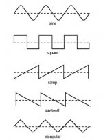
These are all AC waveforms!
See the line cutting through the middle of each waveform? That's the 0v line. The voltage crossing that line means it's switching polarity from positive to negative. It's
alternating polarity.
Alternating polarity, that's just about what this thread has become.
OP, sorry for the thread derailment.
Merican Loco, what waveform is considered an actual sine AC waveform, the kind that would come from your utility?
Let's quote the rest of your internet source:
"
Some AC waveforms are irregular or complicated. Square or sawtooth waves are produced by certain types of electronic oscillators, and by a low-end UPS (uninterruptible power supply) when it is operating from its battery. Irregular AC waves are produced by audio amplifiers that deal with analog voice signals and/or music.
The sine wave is unique in that it represents energy entirely concentrated at a single frequency. An ideal, unmodulated wireless signal has a sine waveform, with a frequency usually measured in megahertz (MHz) or gigahertz (GHz). Household utility current
has a sine waveform with a frequency of 60 Hz in most countries including the United States, although in some countries it is 50 Hz."

 kodah by Skip Albright, on Flickr