
You are using an out of date browser. It may not display this or other websites correctly.
You should upgrade or use an alternative browser.
You should upgrade or use an alternative browser.
12 Volt relay for only 3 volts.
- Thread starter Skooterj
- Start date
manwithtools
ALLIANCE MEMBER
Anything under 12 volts is fine on the NO or NC contacts.
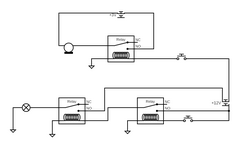
So this should work then? I am adding a hidden garage door opener to my riding mower. I added lights this winter, and they work great. My mower has a cut out for a standard Toyota style switch, and I found a dual switch that fits in the same opening. The first relay in the bottom circuit is a latching relay, as the dual switch is a Momentary. But the wiring of the dual switch only allows one input voltage, and the latching relay is 12 volts. My thought was to use the top relay as a replacement for microswitch on the garage remote.
Innovate1
Well-known member
That diagram is very confusing. A few more labels would help. I don't see how the lower portion is latching. And the upper part would work for the remote but the relay contacts need to be in parallel with the internal switch contacts - I'm guessing the switch marked 3V at the top is the remote switch. And what are the contacts on the right marked "+12V"?
manwithtools
ALLIANCE MEMBER
The 3V and 12V nearby symbols are supposed to represent batteries (power sources) I think. Diagram needs a little more labeling...
The symbol at the right is the mowers battery. The first relay in the circuit is a complete latching relay. The free circuit drawing software I used online did not have a symbol for a latching relay. So the bottom momentary switch will activate and de-activate the latching relay with each push. The latching relay will then trigger the standard relay. So push the button once, lights on. Push again, lights off.
Innovate1
Well-known member
That makes a bit more sense and will probably work like you want. But the drawing is awful - the 12 v battery doesn't even have a connection to ground. If you're going to be drawing circuits, latching relay limitations aside, you either need to learn how to use it or, if it really can't do things like batteries properly, find some other software. Or use a pencil and take a pic to post.
Innovate1
Well-known member
I was going to explain why they needed a relay but then I realized they really don't. Just wire the contacts in parallel across the remote switch. The switch has 12V on one contact but as long as the remote circuitry is isolated from the frame of the mower it will work fine.No need for a relay on a door opener switch. Open the switch up and just make it a momentary.
But both sides of the switch share an input. 12 Volts is needed across this input the activate the relay for the lights. Won't this same 12 Volts then flow from the switch into the Garage Door Remote? Isn't that a problem? (And the spelling error on the picture are not mine)No need for a relay on a door opener switch. Open the switch up and just make it a momentary.
And the switch is already a momentary, which is why I need the latching relay on the lighting branch.

But both sides of the switch share an input. 12 Volts is needed across this input the activate the relay for the lights. Won't this same 12 Volts then flow from the switch into the Garage Door Remote? Isn't that a problem? (And the spelling error on the picture are not mine)
And the switch is already a momentary, which is why I need the latching relay on the lighting branch.
What opener are you trying to interface this with?
If it needs 3 volts I'd wire in a voltage regulator.
I can't wrap my head around why it would need a latching relay on your momentary switch. GDO switches are typically a momentary signal/switch
Innovate1
Well-known member
Are you sure these switches are momentary? In the pic you posted the upper switch looks pushed in like the buttons lock in and on for the first push and off and out for a second push. Can you post a link to the data sheet or any info on the switch or a link to where you got it. Do you have a meter to measure the resistance between wires? If so you could verify if it is momentary or mechanically latching as I described. I did an image search and similar switches are for lights on vehicles and they should be latching for that.
It appears the switch is a simple mechanical switch but it has two voltage input wires and a ground which seems really strange. Maybe it has some circuitry inside? Really need more info but it probably came from China so maybe you didn't get any. You could check operation with a meter if you have one. Hard to give much help without knowing how the switch works.
It appears the switch is a simple mechanical switch but it has two voltage input wires and a ground which seems really strange. Maybe it has some circuitry inside? Really need more info but it probably came from China so maybe you didn't get any. You could check operation with a meter if you have one. Hard to give much help without knowing how the switch works.
Because the bottom half of the switch is being used to turn on and off lights. The latching relay is only on the light side of the circuit.What opener are you trying to interface this with?
If it needs 3 volts I'd wire in a voltage regulator.
I can't wrap my head around why it would need a latching relay on your momentary switch. GDO switches are typically a momentary signal/switch
And I'm just going to use a standard, single button Chamberlain remote with the relay soldered across the microswitch inside the remote.
Last edited:
The Yellow and Black wires are for lights inside the switch. And yes, my actual switch is Momentary. They make the switch in either mechanically latching or momentary. But both sides of the switch have to be the same. I went with the dual momentary because I already had the 12 volt latching relay and I didn't want to accidentally leave the GDO energized.Are you sure these switches are momentary? In the pic you posted the upper switch looks pushed in like the buttons lock in and on for the first push and off and out for a second push. Can you post a link to the data sheet or any info on the switch or a link to where you got it. Do you have a meter to measure the resistance between wires? If so you could verify if it is momentary or mechanically latching as I described. I did an image search and similar switches are for lights on vehicles and they should be latching for that.
It appears the switch is a simple mechanical switch but it has two voltage input wires and a ground which seems really strange. Maybe it has some circuitry inside? Really need more info but it probably came from China so maybe you didn't get any. You could check operation with a meter if you have one. Hard to give much help without knowing how the switch works.

Custom Laser-Etched Dual Push Switches for Toyota
<span style="color: #000000;">Custom Laser-Etched Dual Push Switches for Toyota are perfect when you have limited space or wish to maximize your existing OEM switch locations, this dual switch doubles the number of switches you can install without the need to damage your vehicles dash by cutting...
 theswitchmasters.com
Innovate1
Well-known member
The say the switch is "electronic" but I doubt there is any electronics inside - probably just contacts and lights. I'm guessing they say that to mean you can't power high power loads directly. It could be easily verified with a meter.The Yellow and Black wires are for lights inside the switch. And yes, my actual switch is Momentary. They make the switch in either mechanically latching or momentary. But both sides of the switch have to be the same. I went with the dual momentary because I already had the 12 volt latching relay and I didn't want to accidentally leave the GDO energized.
Custom Laser-Etched Dual Push Switches for Toyota
<span style="color: #000000;">Custom Laser-Etched Dual Push Switches for Toyota are perfect when you have limited space or wish to maximize your existing OEM switch locations, this dual switch doubles the number of switches you can install without the need to damage your vehicles dash by cutting...
For the lights a latching circuit is needed. You need to have a circuit that will latch the output on with one push and latch it off with another push. This is more than a basic latching relay that stays on with one input and needs a second contact to break a circuit to unlatch it. Google is your friend - use "spst momentary switch to latching relay" or similar. I don't see how you will do this with just multiple simple relays. Here's one solution that uses a dual coil relay. I
https://www.learningelectronics.net/circuits/momentary-switch-teamed-with-latching_03.html
It could be done with electronics also but I don't have a circuit handy.
This is getting beyond simple wiring diagrams and I usually get paid for this level of design...
I have a self contained, circuit driven bistable latching relay already. I didn't need help with the light side of the circuit. Push bottom half of button, energize latching relay which energizes high amperage relay, lights on. Push bottom button again, de-energize latching relay which de-energizes high amperage relay, lights off. The latching relay is rated for 10 Amps, but my lights are rated at 15 Amps, so I need both relays.The say the switch is "electronic" but I doubt there is any electronics inside - probably just contacts and lights. I'm guessing they say that to mean you can't power high power loads directly. It could be easily verified with a meter.
For the lights a latching circuit is needed. You need to have a circuit that will latch the output on with one push and latch it off with another push. This is more than a basic latching relay that stays on with one input and needs a second contact to break a circuit to unlatch it. Google is your friend - use "spst momentary switch to latching relay" or similar. I don't see how you will do this with just multiple simple relays. Here's one solution that uses a dual coil relay. I
https://www.learningelectronics.net/circuits/momentary-switch-teamed-with-latching_03.html
It could be done with electronics also but I don't have a circuit handy.
This is getting beyond simple wiring diagrams and I usually get paid for this level of design...
All I really needed to know was the fact that a standard 12 Volt automotive relay would work with a lower voltage on the switched side because I didn't want to send 12 volts through my 3 volt Garage Door Remote. Push button, energize relay, relay closes GDO remote microswitch, release button, de-energize relay, relay de-energizes GDO microswitch.
inphx
Well-known member
Yes "30" to 87 or 87a can be your 3v

Innovate1
Well-known member
Fair enough. That was not at all clear from your earlier posts. Yes, using a relay for the 3V remote is fine. There is no connection between coil and contacts in the relay so if you keep the connections separate there will be no 12V on the remote.I have a self contained, circuit driven bistable latching relay already. I didn't need help with the light side of the circuit. Push bottom half of button, energize latching relay which energizes high amperage relay, lights on. Push bottom button again, de-energize latching relay which de-energizes high amperage relay, lights off. The latching relay is rated for 10 Amps, but my lights are rated at 15 Amps, so I need both relays.
All I really needed to know was the fact that a standard 12 Volt automotive relay would work with a lower voltage on the switched side because I didn't want to send 12 volts through my 3 volt Garage Door Remote. Push button, energize relay, relay closes GDO remote microswitch, release button, de-energize relay, relay de-energizes GDO microswitch.
Viper98912
Well-known member
I am wildly confused by what you're trying to do here. (and I promise I'm trying to be respectful!)
1) Stop overthinking it and mount the remote to your mower. Why does it need to be a "hidden" button? Is someone riding your mower that you don't want breaking into your garage? But then will be opening and closing your garage constantly as they try to figure out what the button does?
2) If you want to complicate things, then open up the remote and take out the board and mount it somewhere in your mower (which, is now less contained than the original remote case), solder in a couple wires and then mount to your switch. You'll need to keep the same 3V battery mounted to the board, unless you planned on having a different 3V battery or step-down transformer (adding more unnecessary complexity).
3) I've never heard of the term "toyota style" switch, but perhaps I'm just not in the know.
4) I still don't understand the purpose of the 3 relays if all you're trying to mimic is a momentary contact? You still need the remote's circuit board as it contains the signal generator for the opener...?
1) Stop overthinking it and mount the remote to your mower. Why does it need to be a "hidden" button? Is someone riding your mower that you don't want breaking into your garage? But then will be opening and closing your garage constantly as they try to figure out what the button does?
2) If you want to complicate things, then open up the remote and take out the board and mount it somewhere in your mower (which, is now less contained than the original remote case), solder in a couple wires and then mount to your switch. You'll need to keep the same 3V battery mounted to the board, unless you planned on having a different 3V battery or step-down transformer (adding more unnecessary complexity).
3) I've never heard of the term "toyota style" switch, but perhaps I'm just not in the know.
4) I still don't understand the purpose of the 3 relays if all you're trying to mimic is a momentary contact? You still need the remote's circuit board as it contains the signal generator for the opener...?
Last edited:
Viper98912
Well-known member
I took some more time to think about the diagram some more and I think I understand a little more about what you're trying to do.
From what I see, the top half of the diagram is for the remote circuit, the bottom half of the diagram is for the lights.
1) In the bottom half - if the right hand relay is a latching relay, then why do you need the left hand relay? All you've done is repeated a 12V circuit that didn't need repeating. The 87/30 contacts on the right hand relay should go to 12V battery and the lights and you should be fine? (PS - are you required to invert the polarity to release the latch in your relay?)
2) In the top half - you don't need any voltage, you just need 87/30 contacts wired to the contacts of the remote circuit board. You just need it to make electrical contact (close the circuit) to mimic the remote's switch, assuming you're keeping the 3V battery that's on the remote's circuit board. If you're not and using a different 3V source and only wiring the downstream-side of the remote's switch, then ok, but that sounds like a really complicated way of doing it...
From what I see, the top half of the diagram is for the remote circuit, the bottom half of the diagram is for the lights.
1) In the bottom half - if the right hand relay is a latching relay, then why do you need the left hand relay? All you've done is repeated a 12V circuit that didn't need repeating. The 87/30 contacts on the right hand relay should go to 12V battery and the lights and you should be fine? (PS - are you required to invert the polarity to release the latch in your relay?)
2) In the top half - you don't need any voltage, you just need 87/30 contacts wired to the contacts of the remote circuit board. You just need it to make electrical contact (close the circuit) to mimic the remote's switch, assuming you're keeping the 3V battery that's on the remote's circuit board. If you're not and using a different 3V source and only wiring the downstream-side of the remote's switch, then ok, but that sounds like a really complicated way of doing it...
Last edited:
In the bottom half, I need both relays because the latching relay I have is rated for 10 amps and my lights are rated at 15. So I need the latching relay to activate the high power 40A relay else I'll melt the latching relay. And no, pushing the button energizes the latching relay. Pushing it again de-energizes the latching relay. So no need to flop polarity or really do anything other than send a 12V signal to the latching relays internal circuitry.I took some more time to think about the diagram some more and I think I understand a little more about what you're trying to do.
From what I see, the top half of the diagram is for the remote circuit, the bottom half of the diagram is for the lights.
1) In the bottom half - if the right hand relay is a latching relay, then why do you need the left hand relay? All you've done is repeated a 12V circuit that didn't need repeating. The 87/30 contacts on the right hand relay should go to 12V battery and the lights and you should be fine? (PS - are you required to invert the polarity to release the latch in your relay?)
2) In the top half - you don't need any voltage, you just need 87/30 contacts wired to the contacts of the remote circuit board. You just need it to make electrical contact (close the circuit) to mimic the remote's switch, assuming you're keeping the 3V battery that's on the remote's circuit board. If you're not and using a different 3V source and only wiring the downstream-side of the remote's switch, then ok, but that sounds like a really complicated way of doing it...
And yes, in the top half I just need the relay to replicate the remotes microswitch, so I assume it needs to handle 3V because that is the power supplied by the remotes battery. My free schematic drawing software didn't have a way to sketch that out really.
And a Toyota Style switch is pretty standard.
Last edited:
Viper98912
Well-known member
Great scott! 30 amps for lights! Switch to LED's man!!!In the bottom half, I need both relays because the latching relay I have is rated for 10 amps and my lights are rated at 15. So I need the latching relay to activate the high power 40A relay else I'll melt the latching relay. And no, pushing the button energizes the latching relay. Pushing it again de-energizes the latching relay. So no need to flop polarity or really do anything other than send a 12V signal to the latching relays internal circuitry.
And yes, in the top half I just need the relay to replicate the remotes microswitch, so I assume it needs to handle 3V because that is the power supplied by the remotes battery. My free schematic drawing software didn't have a way to sketch that out really.
And a Toyota Style switch is pretty standard.
All jokes aside, now with this additional context, your original design looks fine. It was just a little surprising to see all the complexity but we get it now, it's actually a little simpler than it looks.
I still would've just bolted down the factory remote, but to each their own

dave*99
Well-known member
Mount a cell phone holder and use an app.
Don’t text and mow.

Don’t text and mow.