To avoid these ads, REGISTER NOW!

2 Speed lathe motor to drum switch wiring help needed.

SimplyG

Member
Joined
Apr 19, 2017
Messages
5
Location
Connecticut
I could use some help wiring my lathe.
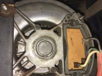
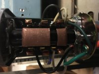
Ignore the wire color coming from the motor as the previous owner wired it with a piece of an extension cord, and the "new" wiring as I have no idea what I'm doing.
The lathe ran fine for a while until the switch started to fail, unfortunately I did not take photos before I disconnected it and now sit here with a new switch and no clue how to wire this.

Any help would be appreciated.
 

Attachments

  • IMG_2088.jpg
    IMG_2088.jpg
    142.9 KB · Views: 35
  • IMG_2089.jpg
    IMG_2089.jpg
    147.1 KB · Views: 29
  • IMG_2092.jpg
    IMG_2092.jpg
    123.5 KB · Views: 29
To avoid these ads, REGISTER NOW!

Bert_

Well-known member
Joined
Dec 24, 2016
Messages
9,880
Location
NW Iowa
Looks like the green wire going into the motor is being used for a current carrying wire, not a ground. This will no doubt work but is not how it should be as you wouldn't have a ground to the motor frame.

Do you have a set of diagrams that should have come with the drum switch. To me that drum switch looks like it's meant for reversing a motor, rather than a 2 speed motor but I'm not sure.
 
OP
S

SimplyG

Member
Joined
Apr 19, 2017
Messages
5
Location
Connecticut
It is made for a reversing motor, it's a Dayton 2x440A. I just purchased an exact copy of what was on there originally.
 

nehog

Well-known member
Joined
Jan 2, 2010
Messages
7,935
Location
Jaffrey, NH
Just a WAG but possibly black is one side of the line, and white is speed one, and green is speed two? An ohm meter should answer which terminal is common and which terminals are the speed selectors.

Measure accurately the resistance between each of the wires to the other two, and post the resistances and I (and probably a few others) can tell you which terminal is which.
 

nehog

Well-known member
Joined
Jan 2, 2010
Messages
7,935
Location
Jaffrey, NH
Looks like the green wire going into the motor is being used for a current carrying wire, not a ground. This will no doubt work but is not how it should be as you wouldn't have a ground to the motor frame...


The motor frame ground is a safety feature and won't keep the motor from running.
 

Bert_

Well-known member
Joined
Dec 24, 2016
Messages
9,880
Location
NW Iowa
The motor frame ground is a safety feature and won't keep the motor from running.

That's why I said it would work. But in the interest of safety a ground wire should be connected.

Since you have no diagrams, the only option you may have is to get an idea by using an ohmmeter, then just try it out.

Do some research on electric motors to understand what your ohmmeter is saying.
 
To avoid these ads, REGISTER NOW!

Dagny

Well-known member
Joined
Jul 25, 2014
Messages
3,059
Location
Northern Wi.
the greens are hooked together on the drum switch meaning there are only two wires left to run the motor.
 
To avoid these ads, REGISTER NOW!
Top Bottom