To avoid these ads, REGISTER NOW!

220 Compressor wiring 2 v 3 wire

R6 Racer

Well-known member
Joined
Feb 21, 2010
Messages
1,632
Location
Northern Ontario Canada
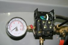
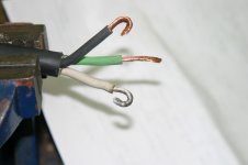
In the past I have run 220 wiring to my garage for my welder & a construction heater. For both of these situations I used a 3 wire set up. Black & red wires for power, white wire for return, with a bare copper wire for a ground. I have run the wire & installed the breaker for my compressor using the same process (3 wire). Only to find this (see pics, I have 2 options), so now i'm kinda lost. I think this is a 2 wire set up or am I confused? I have never used a 2 wire set up before, Can anyone out there can help me out? I am thinking the black & white wires are power & the green a ground, or is the green a return? If the green is a return where is the ground?:headscrat
Also I have 2 options for the wiring switch (see pics) which one do you think is better?

Lost in :canada:
Steve
 

Attachments

  • option 1.jpg
    option 1.jpg
    103.2 KB · Views: 168
  • option 2.jpg
    option 2.jpg
    78.3 KB · Views: 158
To avoid these ads, REGISTER NOW!

harvero

Well-known member
Joined
Nov 16, 2009
Messages
233
Location
Flemington, NJ
I have the same deal on my IR compressor. It is 220v only and does not need a neutral. Since I ran a cord to it, I did not run the neutral to it.
 

wbrian63

Well-known member
Joined
Mar 31, 2010
Messages
843
Location
Houston, TX
I'd stick with the contactor that's already installed on the compressor, which appears to be the left photo.

Are you plugging the compressor in with a cord, or wiring a flex conduit to it?

If you're running a cord, the wires that feed the blades should go to the white/black terminals on the contactor, and the wire for the pin should connect to the ground screw with the green. In the receptical on the wall, hot wires from the breaker to the blade terminals, and green to the pin terminal. Cap the white wire in box. Be sure to use a proper coupling at the contactor that holds the cord sheath tightly without pinching.

If you're running a flex conduit and pulling your own conductors, I'd use blacks for the hot legs, and green for the ground. Again, cap the white wire in the junction box on the wall. (I personally pull a black and a blue wire for hots on a 220v circuit, not two blacks.)

If you're using a flex connector that already has the conductors, if there's a bare wire, that's for the green terminal, black/red are the hots (if there's a red).

Basically, green is never anything but ground. Just hook your two hot lines from the breaker to the open screws on the contactor, and the ground wire from the breaker panel to the screw with the green wire. Cap the white wire at the wall, you don't need it in this application.
 

harvero

Well-known member
Joined
Nov 16, 2009
Messages
233
Location
Flemington, NJ
You just need to run the two hots and the ground.

IMG_20110105_092315.jpg


IMG_20110105_092507.jpg


IMG_20110105_092346.jpg


IMG_20110105_092407.jpg


And yes I need to do a neater job with the cord under the screws.
 
OP
R

R6 Racer

Well-known member
Joined
Feb 21, 2010
Messages
1,632
Location
Northern Ontario Canada
OK I get it now I think, basically I connect the black & red wires from the panel to the black & white wires on the compressor. I should cap off the white wire from the panel & connect the copper wire from the panel to the green wire in the compressor... Right?

I have always referred to the white wire (from the panel) as a "return". How does the 220 2 wire system work without a "return"?

Steve

Steve
 

Chuckw

Well-known member
Joined
Apr 8, 2010
Messages
97
Location
AZ
weird as it is the white is your red at the pressure switch (tape it red) I think you will also find that crimping a tab under on the end of each wire, will allow you to slide them under the plate below the screws you are trying to put the wires under. for what it's worth
 
OP
R

R6 Racer

Well-known member
Joined
Feb 21, 2010
Messages
1,632
Location
Northern Ontario Canada
harvero That looks like an IR SS3L3 or SS5L5 compressor & it looks like your line out from your tank is coming from the same place that your pressure switch & gauge is. If so what size is the hole from the tank? Does that compressor not have another separate "line out" hole?

Steve
 
Last edited:

harvero

Well-known member
Joined
Nov 16, 2009
Messages
233
Location
Flemington, NJ
harvero That looks like an IR SS3L3 or SS5L5 compressor & it looks like your line out from your tank is coming from the same place that your pressure switch & gauge is. If so what size is the hole from the tank? Does that compressor not have another separate "line out" hole?

Steve

There is just the one tap.

IMG_20110105_095436.jpg


Bob
 

harvero

Well-known member
Joined
Nov 16, 2009
Messages
233
Location
Flemington, NJ
weird as it is the white is your red at the pressure switch (tape it red) I think you will also find that crimping a tab under on the end of each wire, will allow you to slide them under the plate below the screws you are trying to put the wires under. for what it's worth

I'm not a big fan of crimp connectors for any thing that uses any power. I've had a few catch fire many years ago. If I use a spade I will solder it.
 

Charles (in GA)

Well-known member
Joined
Jan 11, 2006
Messages
12,489
Location
50 mi south of Atlanta
Never, ever, hook a ground wire, bare or green, to anything other than another ground, a GREEN ground screw or other approved ground or earth grounding point, many times marked with a Christmas tree looking symbol, and always use a green screw for making a ground connection.

Charles
 

boydgti

Active member
Joined
Oct 27, 2010
Messages
33
I'm not a big fan of crimp connectors for any thing that uses any power. I've had a few catch fire many years ago. If I use a spade I will solder it.

Thats ****, im an electrician and we use them all the time, and never had a prob with them. Maybe u are not crimping them correctly, I have never seen or hear anybody soldering them, thats crazy. If u are using white as power u should tape it black or any other colour to indictate power.
 

mrb

Well-known member
Joined
Dec 31, 2008
Messages
3,734
I'm not a big fan of crimp connectors for any thing that uses any power. I've had a few catch fire many years ago. If I use a spade I will solder it.

Solder has no place in line voltage wiring (for the most part) we use crimp connectors all the time, often carrying 16 amps 24/7. You either used bad terminals (dont buy harborfreight crimp terminals) or the wrong tool.
 

harvero

Well-known member
Joined
Nov 16, 2009
Messages
233
Location
Flemington, NJ
Solder has no place in line voltage wiring (for the most part) we use crimp connectors all the time, often carrying 16 amps 24/7. You either used bad terminals (dont buy harborfreight crimp terminals) or the wrong tool.

I use to work for Vydec year back making power supply leads, and then as a QA inspector. Then I had a job fixing Pinball machines and video arcade games. Then I had job fixing and building PCs back in the 80s'. On anything that was not junk the line cord leads had soldered terminals. But you know better. I'm going to solder mine.
 

mrb

Well-known member
Joined
Dec 31, 2008
Messages
3,734
I use to work for Vydec year back making power supply leads, and then as a QA inspector. Then I had a job fixing Pinball machines and video arcade games. Then I had job fixing and building PCs back in the 80s'. On anything that was not junk the line cord leads had soldered terminals. But you know better. I'm going to solder mine.

I said 'for the most part'. the applications you speak of sound like they warrant soldered connections. I still say soldering a crimp terminal instead of crimping it is ill advised. (also, NEC prohibits soldering ground connections -for good reason). And a quality terminal, properly crimped, is the best way to get a stranded wire under a screw.
 

boydgti

Active member
Joined
Oct 27, 2010
Messages
33
I use to work for Vydec year back making power supply leads, and then as a QA inspector. Then I had a job fixing Pinball machines and video arcade games. Then I had job fixing and building PCs back in the 80s'. On anything that was not junk the line cord leads had soldered terminals. But you know better. I'm going to solder mine.

whatever buddy I guess U know best, and go ahead and solder it. It doesnt sound like u know much about electrical anyways considering u werent sure how too hook up a simple compressor. I never understand why ppl dont listen too electricans that know what they are talking about, I do this for a living.
 
To avoid these ads, REGISTER NOW!

MrMark

Well-known member
Joined
Jan 25, 2010
Messages
4,626
Location
Southern Cal.
whatever buddy I guess U know best, and go ahead and solder it. It doesnt sound like u know much about electrical anyways considering u werent sure how too hook up a simple compressor. I never understand why ppl dont listen too electricans that know what they are talking about, I do this for a living.

That's kind of uncalled for. Just because you do something for a living doesn't mean you know squat.
 

ishiboo

Well-known member
Joined
Oct 27, 2010
Messages
9,481
Location
Oshkosh, WI
I said 'for the most part'. the applications you speak of sound like they warrant soldered connections. I still say soldering a crimp terminal instead of crimping it is ill advised. (also, NEC prohibits soldering ground connections -for good reason). And a quality terminal, properly crimped, is the best way to get a stranded wire under a screw.

Premise wiring/etc this is completely true. On a compressor wire with a cord like that, solder is going to be an issue due to the vibration and flex of the cord and would not be a good idea. A quality spade connector with a proper ratcheting crimp tool is the way to go... though the bare wire under the screw terminal doesn't even look that bad to me.

Pinball machines are a bad example as they are an appliance, like your TV, computer, etc... of course there is soldering going on inside, even on the line voltage side. These are different connections subject to different forces. From the power cord to the point where it enters a strain relief on an appliance, there is no need and often reasons not to use solder. Inside; sure.
 
OP
R

R6 Racer

Well-known member
Joined
Feb 21, 2010
Messages
1,632
Location
Northern Ontario Canada
I am not an electrician. I don't know whats right or code. I just try & use common sense, in the past when hooking a stranded wire up to a screwed terminal like the one shown in the earlier pics, I have twisted the wire, then made a hook shape that matched the screw out of it. Then soldered it into a solid piece that shape (see pic). I found that this would make a very solid connection. Since I am going to put a plug on my compressor and will be using a stranded wire this what I was going to do. Will I be OK with this?

Steve
 

Attachments

  • IMG_4605.jpg
    IMG_4605.jpg
    65.7 KB · Views: 30

Charles (in GA)

Well-known member
Joined
Jan 11, 2006
Messages
12,489
Location
50 mi south of Atlanta
I am not an electrician. I don't know whats right or code. I just try & use common sense, in the past when hooking a stranded wire up to a screwed terminal like the one shown in the earlier pics, I have twisted the wire, then made a hook shape that matched the screw out of it. Then soldered it into a solid piece that shape (see pic). I found that this would make a very solid connection. Since I am going to put a plug on my compressor and will be using a stranded wire this what I was going to do. Will I be OK with this?

Steve

I frequently tin fine stranded cord wire when it wants to spread and work its way out from under a screw terminal as you tighten it.

Charles
 

mrb

Well-known member
Joined
Dec 31, 2008
Messages
3,734
I frequently tin fine stranded cord wire when it wants to spread and work its way out from under a screw terminal as you tighten it.

Charles


although I do it on medium base lamp sockets, I try to avoid it for the most part as the solder cold flows once the screw is tightened resulting in a loose screw.
 

timgr

Well-known member
Joined
Dec 19, 2006
Messages
544
Location
Medford, MA USA
OK I get it now I think, basically I connect the black & red wires from the panel to the black & white wires on the compressor. I should cap off the white wire from the panel & connect the copper wire from the panel to the green wire in the compressor... Right?

I have always referred to the white wire (from the panel) as a "return". How does the 220 2 wire system work without a "return"?

Steve

Steve

Did anybody answer your question? This is single phase 240 (or 230... same). The two 240 wires are basically two 120s. The "return" or neutral wire splits the 240 right down the middle, at nominal ground potential. One of your 240 wires is at 120v above neutral, and the other is 120v below neutral. The voltage potential between them is 240V.

You don't need the neutral wire if your 240V device does not need 120. Something like an electric clothes dryer uses 120 for the timer circuit, so in that case you need the neutral (4 wires) so you can split the 240 in half for the timer. If there's no need for 120, there's no need for a neutral.
 
Last edited:

MrMark

Well-known member
Joined
Jan 25, 2010
Messages
4,626
Location
Southern Cal.
The current return on the 240 set up is through each phase leg. They are opposite polarity current waveforms (2 distinct phases whatever anyone else tells you) where the current reverses direction at a frequency of 60 Hz. It's the same as the 120 Volt situation, except that instead of the neutral at 0 volts, you have an inverted phase wire such that the net voltage across the load is 240.
 
OP
R

R6 Racer

Well-known member
Joined
Feb 21, 2010
Messages
1,632
Location
Northern Ontario Canada
Thanks timgr & MrMark for your explanations... now I get it!
I soldered the stranded wire with 95/5 solder, thats one hard loop! Its connected to the compressor now & looks to be very solid, I'm going to leave it like that unless someone can tell me why I should change it & what to change it to. Now i'm just waiting to go pick up a plug & socket to finish the hook up.

Thanks for all the help.
Steve
 

-JP

Well-known member
Joined
Apr 22, 2008
Messages
118
Location
Racing Capitol of the World
Line (over 50v) voltage connections should never be soldered.

The solder will "flow" over time and you will have a loose connection.

Loose connections create increased resistance and the subsequant heat developed can/will cause the solder to turn into a liquid state.

The solution is to use solid conductors instead of stranded. All commercial bid/spec projects do not allow any stranded conductors for #10AWG and smaller.

JP
 

Norcal

Well-known member
Joined
Mar 16, 2008
Messages
13,775
All commercial bid/spec projects do not allow any stranded conductors for #10AWG and smaller.

JP


A major reason solid wire is used for commercial projects is it's cheaper then stranded.
 

-JP

Well-known member
Joined
Apr 22, 2008
Messages
118
Location
Racing Capitol of the World
Actually the prime reason is to control the quality of terminations.

Cost is not an issue as difference is negligible.

Contractors would prefer to use stranded over solid because it is much easier to pull. Some of them ask and never want more money but I never approve it.

JP
 

mrb

Well-known member
Joined
Dec 31, 2008
Messages
3,734
All commercial bid/spec projects do not allow any stranded conductors for #10AWG and smaller.

JP


I take it these are projects YOU spec that do not allow these stranded conductors?
 

Norcal

Well-known member
Joined
Mar 16, 2008
Messages
13,775
Quote:
Originally Posted by -JP
All commercial bid/spec projects do not allow any stranded conductors for #10AWG and smaller.

JP


I take it these are projects YOU spec that do not allow these stranded conductors?

It's his opinion not facts, a stranded or solid conductor can be terminated equally in a safe/code compliant/ reliable manner.
 

mrb

Well-known member
Joined
Dec 31, 2008
Messages
3,734
Quote:
Originally Posted by -JP
All commercial bid/spec projects do not allow any stranded conductors for #10AWG and smaller.

JP


It's his opinion not facts, a stranded or solid conductor can be terminated equally in a safe/code compliant/ reliable manner.

right. i wanted it clarified for the benefit of others that come across the post. I didnt want someone thinking its not ok to use #10 stranded for example.
 

Aceman

Well-known member
Joined
Jan 28, 2007
Messages
2,513
Location
Eastern Oregon
It's his opinion not facts, a stranded or solid conductor can be terminated equally in a safe/code compliant/ reliable manner.

I agree. I can only remember one job doing one phase of a hospital remodel we did that required solid conductors. There have been several phases since then that didn't require it, I can only think it must of been one particular EE that wanted it at the time. I personally don't care for solid wire in pipe....

I'd honestly be surprised if the supply houses around here had solid on the shelf...nobody uses it.
 

-JP

Well-known member
Joined
Apr 22, 2008
Messages
118
Location
Racing Capitol of the World
Your comments are well taken and perhaps I should not have used the word "All" in referencing specification requirements for commercial projects.

It is true that the Engineer of Record has the right to modify his specifications as he desires but my comment is based upon 25 years experience in the construction business and my familiarity with specifications utilized by the majority of the A/E firms across the country.

A very high percentage of the A/E firms utilize a specification subscription service to maintain the quality, accuracy, and applicability of their specifications by utilizing a subscription service such as the one from the American Institute of Architects (AIA). Doing so relieves them of the burden to keep up with the multitude of changes that take place in the industry with not only products, codes, reference standards, but also installation methods.

I am fortunate to have been invited to participate for years as one of the 5 member technical committee that edits and provides updates to all of the electrical specifications for the specification subscription series used by more A/E firms than any other available. We meet for several long days twice a year in DC to review and update a few sections of the specs each time.

It is with this history that I made my comments knowing that the requirement for solid conductors has been included in ALL specifications provided by the large spec writers and also included in every commercial spec I have ever seen that was produced by a decent size A/E firm.

As I said, there is always the option that an engineer will make a change but that would be rare if he is experienced and understand the issues. There are many small time engineering firms that don't want to spend the money to keep their spec up to date or are just using a poor quality boilerplate spec to work with and that usually shows itself in the end.

OK, I am starting to rant...

Bottom line is the solid conductor requirement is a standard followed by the serious commercial projects. I did not say it is a code requirement. Sorry if I gave anyone that impression.

JP
 
To avoid these ads, REGISTER NOW!
Top Bottom