To avoid these ads, REGISTER NOW!

240v Air Compressor-Not enough power from wall

Model A Fan

Well-known member
Joined
Dec 1, 2011
Messages
1,223
Location
NW Washington
OK, I bought the compressor in the photos thinking my wall was wired for something as heavy duty as it. However, after running it for a little while, it would cycle up and down and then die.

I tested my wall and lo-and-behold, its only putting 120v out. The compressor calls for 240v. How would one rewire this compressor or would it be best to rewire the garage portion for this? The breaker switch is a double pole breaker (two prongs connected by a flat plastic so it is one) instead of the normal breaker switch which is just one (like a light switch).

Thanks! :rocker:

IMG_4305.jpg


IMG_4306.jpg


IMG_4307.jpg
 
To avoid these ads, REGISTER NOW!

Charlie9000

Member
Joined
Jun 2, 2012
Messages
21
Location
Alberta, Canada
Hi Model A Fan,

I'm not an electrician, but on my Federal (Stab-loc) panel, I would check to ensure that both conductors are actually wired to the breaker, and not one to one pole of the breaker and one to the return bus. Once that's fixed, make sure that the double pole breaker is installed in the panel so that each pole is connected to a separate line or you will go from 120v down to 0v.
 
Last edited:

930dreamer

Super Moderator
Staff member
Joined
Oct 7, 2009
Messages
22,981
Location
Amarillo,TX and Stinnett,TX
The motor is 240V only so your looking at adding a 240V circuit to the garage. The other option is replacing the motor with a 120V one, but that will cause performance issue also.:eek:
 

pattenp

Well-known member
Joined
Jun 4, 2008
Messages
10,175
Location
Virginia - USA
Model A, what you're saying makes no sense. First you should not be able to plug a 240V plug from the compressor into a 120V outlet, it just won't fit. Second a 120V circuit is not run off of a 2 pole breaker unless it's a multi-branch circuit which I doubt it is. When you checked the voltage at the outlet did you check across both of the plug spade holes or did you go from one one spade hole to the ground hole? Across the two spades you should get 240V and across one spade and the ground you'll get 120V.

Did you wire the cord and plug on the compressor or did it come with a cord and plug?
 
Last edited:

Steevo

Well-known member
Joined
Aug 18, 2009
Messages
8,738
Location
43.49600, -112.04300
What pattenp said . . .

"Across the two spades you should get 240V and across one spade and the ground you'll get 120V"

That's only a 3.xhp motor, so shouldn't need a lot of amps, either. Should run off a 30A breaker with 10ga wire just fine.
 
Last edited:

pattenp

Well-known member
Joined
Jun 4, 2008
Messages
10,175
Location
Virginia - USA
The motor plate shows 15A, so you can get by with #12 wire on a 20A breaker. If the the outlet you used is a single dedicated outlet and is on #12 or #10 you just need to sort out the breaker on the other end to be a proper installed 2 pole 20A or 30A. Plus make sure you use the proper 240V plug and outlet for the circuit amperage.
 
OP
M

Model A Fan

Well-known member
Joined
Dec 1, 2011
Messages
1,223
Location
NW Washington
I switched the plug out on my own. The one that was in its spot originally said 250v and 25 amp or something like that. Its in my garage now. I just figured it was a higher volt outlet given the double pole breaker and the plug that was already on it...
 

Tscott

Well-known member
Joined
Oct 17, 2006
Messages
1,484
Location
Keystone Heights, FL.
Ok, I'm officially confused. You swapped the plug out or the outlet out? Perhaps we can standardize the terminology here for everyone's convenience?

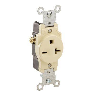
Plug = Male end of air compressors cord (i.e. the plastic thing on the compressor with the metal pointy bits sticking out.

Outlet = Female receptacle in the wall of your garage that the aforementioned metal pointy bits stab into.

So what did you swap?

Here is the simple version of what you need. You need to put an outlet in the wall that will fit your air compressors plug. You need a 2 pole 20 amp breaker to feed that outlet (assuming you have 12awg wire between the panel and the outlet, this should be written on the wire). You should have 3 wires traveling from the breaker to the outlet in the wall, most likely a white, a black (or maybe red) and a green wire. At the breaker end you will need to make sure the white wire and the black wire are both connected to the breaker, each to its own terminal. The green wire should already be connected to the common ground in the load center. On the outlet end, you need the white and black wires connected to the screws on the side of the outlet. The terminals you need are typically on separate sides of the outlet. The green will go to the common ground in the box the outlet is in, or to the green screw on the outlet itself if it has one.

If this is not clear enough, then I might suggest you get a buddy to come help, or call an electrician. Perhaps you should post some pics of the critical areas we are all asking about. The outlet and box and the breaker panel.

Tom
 

Mmfh

MEMBER EMERITUS
Joined
Oct 8, 2011
Messages
1,423
Location
Portland Oregon
Model A, hate to say it but it sounds like you may be a little over your head. Do you have any friends that know something about electricity??

Might save you from burning something up?

Mm
 

PT Doc

Well-known member
Joined
Nov 12, 2010
Messages
3,197
Just a recommendation, but it might be a good idea to have a flexible hose that comes out the compressors bung instead of going rigid immediately. Just a preference but do as you please.
 
To avoid these ads, REGISTER NOW!

pattenp

Well-known member
Joined
Jun 4, 2008
Messages
10,175
Location
Virginia - USA
I didn't notice that in the picture. Very good point, should be a flex fitting to handle vibration/movement.

Just a recommendation, but it might be a good idea to have a flexible hose that comes out the compressors bung instead of going rigid immediately. Just a preference but do as you please.
 

SiGmA_X

Well-known member
Joined
Aug 13, 2005
Messages
1,111
Location
Portland, OR
OP, can you post pictures of the receptacle ('outlet') and the plug, and a shot of the breaker panel with the cover off?

I'd strongly agree with the installation of a flex hose before your hard run, for aforementioned reasons. I picked up a section of 1/2" hose and a 1/2" coupler for on the compressor, in case we ever wanted to move the compressor. My setup also includes a 1/2" shutoff valve, seemed like a logical thing to put on the discharge of the storage vessel.
 

koditten

Well-known member
Joined
Apr 10, 2008
Messages
5,528
Location
Midland, Michigan
I agree on the pics needed of the plug and receptical. We can help you after those pics appear.

I wouldn't worry about the plumbing, just yet. The only thing wrong with that is the compressor will transfer vibrations to your structure and make the compressor sound louder than it is. Just put the plumbing on you to do list, for now.

KO
 

Thruxton

Well-known member
Joined
Dec 30, 2010
Messages
767
Location
Virginia
I agree on the pics needed of the plug and receptical. We can help you after those pics appear.

I wouldn't worry about the plumbing, just yet. The only thing wrong with that is the compressor will transfer vibrations to your structure and make the compressor sound louder than it is. Just put the plumbing on you to do list, for now.

KO

True. I had my compressor plumbed directly to 3/4 rigid for 12-13 years. Didn't do any damage, but as part of my shop re-do I installed a short piece of 3/4 flexible hose between the compressor and the 3/4 black pipe, much less noise in the shop now.
 

J Persons

Well-known member
Joined
Jul 27, 2010
Messages
640
Location
Louisiana
Amazon.com has a ½" dia 3' Goodyear hose with brass NPT ends for about $14.00, works great for isolating the compressor from the rigid lines and cuts down on the noise.
 

-JP

Well-known member
Joined
Apr 22, 2008
Messages
118
Location
Racing Capitol of the World
Since we are providing comments about the OP installation while we wait for his return with photos, I also noticed he ran out horizontal from the regulator to the wall where he then turns up with an elbow.

There should be a TEE fitting instead of the elbow so there can be a drain provided at the down leg. All the condensation water will be trapped in the run up the wall next to the output of the regulator. A drain at the TEE fitting would allow periodic relief of the water in the line.

JP
 

Kevin C

Well-known member
Joined
Aug 4, 2011
Messages
1,653
Location
Portland OR
The flex connectors are a lot more important when hooking into dryer unit. The tubing in them is a lot more fragile.

Kevin
 

Socophreak

Well-known member
Joined
Jun 18, 2010
Messages
231
Since we are providing comments about the OP installation while we wait for his return with photos, I also noticed he ran out horizontal from the regulator to the wall where he then turns up with an elbow.

There should be a TEE fitting instead of the elbow so there can be a drain provided at the down leg. All the condensation water will be trapped in the run up the wall next to the output of the regulator. A drain at the TEE fitting would allow periodic relief of the water in the line.

JP

Would also be a good idea to add a ball valve around the regulator.
 
To avoid these ads, REGISTER NOW!
Top Bottom