To avoid these ads, REGISTER NOW!

258v on a 240v outlet

Status
Not open for further replies.

FL Guy

Well-known member
Joined
Dec 21, 2022
Messages
302
It’s me again…
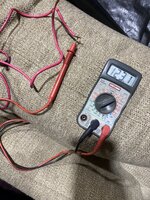
Just installed 70’ of 10 awg wire for a 240v mini split. The ends of the wires were reading 258v-263 & 128v-131v respectively.
When I took the voltage at the breaker, I was around 243v & 123v.

Why would the voltage be different?
 
To avoid these ads, REGISTER NOW!

wyliesdiesels

Well-known member
Joined
Aug 14, 2012
Messages
20,014
Location
Modesto, CA
not possible to have higher voltage at the end of a run like that

check batteries as said above

also when you measured 1 leg to neutral or ground did you read the other as well? what was the result?
 

Cruzan80

Well-known member
Joined
Jul 22, 2015
Messages
4,215
Location
Denver, CO
not possible to have higher voltage at the end of a run like that

check batteries as said above

also when you measured 1 leg to neutral or ground did you read the other as well? what was the result?
That is why I started by restating what I thought I read. My reaction was the same as your first sentence above.
 
OP
F

FL Guy

Well-known member
Joined
Dec 21, 2022
Messages
302
Correct. Ill be home shortly, switch batteries and try again.
To be clear, you are saying that the ends of a 70ft run are reading 15V higher hot-to-hot, and 5-8V higher hot-to-ground than you are getting at the beginning of the run at the breaker?

Have you checked the batteries in your multi-meter recently?
 
OP
F

FL Guy

Well-known member
Joined
Dec 21, 2022
Messages
302
not possible to have higher voltage at the end of a run like that

check batteries as said above

also when you measured 1 leg to neutral or ground did you read the other as well? what was the result?

Both legs measured the same high voltage
 

Cruzan80

Well-known member
Joined
Jul 22, 2015
Messages
4,215
Location
Denver, CO
In what sense? The 10A has a higher fuse than the COM, so I dont think he hurt the meter doing so. However, the "mini-brain" isn't expecting the other fuse to be there, so it is (probably) showing incorrect numbers.

This would be my guess, though I wouldn't trust the meter for discrete measurements as it is (lcd damaged, looks beat up, etc). Probably fine for relative measurements between two items when wired correctly.
 

PCustoms

Well-known member
Joined
Jul 23, 2011
Messages
22,870
Location
VT
In what sense? The 10A has a higher fuse than the COM, so I dont think he hurt the meter doing so. However, the "mini-brain" isn't expecting the other fuse to be there, so it is (probably) showing incorrect numbers.

I'm just surprised it reads anything, as I wouldn't expect that to be wired in a way to even remotely measure voltage.
 

rlitman

Well-known member
Joined
Oct 18, 2010
Messages
24,609
Location
Long Island
In what sense? The 10A has a higher fuse than the COM, so I dont think he hurt the meter...
Um, no, and he's lucky he didn't blow himself up. Those 10A ports are very dangerous in untrained hands.

On that style of meter, there is typically a 16 gauge solid copper wire that shunts the 10A port to the common port. The meter then measures the voltage drop across the shunt of a known resistance to calculate current. This Craftsman meter happens to be fuse protected, but I've seen plenty of similar meters that have no real protection on the 10A port.

Fl Guy, do yourself a big favor and put a piece of tape over the 10A port on your meter, and then take new readings.
 

wyliesdiesels

Well-known member
Joined
Aug 14, 2012
Messages
20,014
Location
Modesto, CA
In what sense? The 10A has a higher fuse than the COM, so I dont think he hurt the meter doing so. However, the "mini-brain" isn't expecting the other fuse to be there, so it is (probably) showing incorrect numbers.

This would be my guess, though I wouldn't trust the meter for discrete measurements as it is (lcd damaged, looks beat up, etc). Probably fine for relative measurements between two items when wired correctly.
its not about hurting the meter....
 

Wrench97

Well-known member
Joined
Jun 23, 2018
Messages
12,101
Location
Southeastern Pa
The amp socket reads across a connection so using it from hot to hot should have melted the fuse in the meter and had it read 0.
 

Cruzan80

Well-known member
Joined
Jul 22, 2015
Messages
4,215
Location
Denver, CO
Sorry, most/all of mine have a fused 10A port. I saw on his that it also said "Fused". The comment you both are quoting was me responding to was in response to "Is the Meter still good?". I had already pointed out to FL Guy that he was using the wrong ports...

Not suggesting he use the 10A port, or that it was correct to do so. I am also not sure why it was still reading anything and not blowing the fuse.

PCCustoms - "Is that meter even good anymore?"
Me - "I dont think he hurt the meter doing so"
Wyliediesels - "its not about hurting the meter...."
 

wyliesdiesels

Well-known member
Joined
Aug 14, 2012
Messages
20,014
Location
Modesto, CA
Sorry, most/all of mine have a fused 10A port. I saw on his that it also said "Fused". The comment you both are quoting was me responding to was in response to "Is the Meter still good?".

Not suggesting he use the 10A port, or that it was correct to do so. I am also not sure why it was still reading anything and not blowing the fuse.
who knows if there is even a real fuse in it... could be a boot leg fuse :lol_hitti :FIREdevil
 

rlitman

Well-known member
Joined
Oct 18, 2010
Messages
24,609
Location
Long Island
The amp socket reads across a connection so using it from hot to hot should have melted the fuse in the meter and had it read 0.
On an analog meter I would agree, but this is a high impedance digital meter. I suspect it's current induced on the shunt that's creating phantom readings where the coil resistance in a d'Arsonval analog meter would pull that voltage down to 0. Regardless of where the numbers are coming from, he needs to get that wire out of the 10A port.
 
To avoid these ads, REGISTER NOW!

Wrench97

Well-known member
Joined
Jun 23, 2018
Messages
12,101
Location
Southeastern Pa
On an analog meter I would agree, but this is a high impedance digital meter. I suspect it's current induced on the shunt that's creating phantom readings where the coil resistance in a d'Arsonval analog meter would pull that voltage down to 0. Regardless of where the numbers are coming from, he needs to get that wire out of the 10A port.
From the Craftsman 82141 manual there is a 10a 250v fuse.
I had one those years ago and had to change that fuse several times........

1719009025617.png
 

PCustoms

Well-known member
Joined
Jul 23, 2011
Messages
22,870
Location
VT
From the Craftsman 82141 manual there is a 10a 250v fuse.
I had one those years ago and had to change that fuse several times........

Didn't learn fast, did you? Lol

#4 says throw it away to me:


I had a similar one years ago, it was red. Took it out of the toolbox one day and the screen was dim to the point it wasn't readable. Changed the battery and didn't get better. Threw it away and bought a Klein toughmeter
 

RPH

Well-known member
Joined
Dec 17, 2006
Messages
4,190
Location
Michigan Thumb
Agree that the meter should be replaced. They do drift over time and become inaccurate. If there is thing I require of my electrical instruments is accuracy. If I can’t trust what the meter tells me. I don’t use it until it’s verified. The instruments are between me and the circuit. Don’t play games with electricity, it’s a killer.
 
OP
F

FL Guy

Well-known member
Joined
Dec 21, 2022
Messages
302
Swapped the wires around and still getting high reading at wires.
Battery was replaced as well.

I see some of y’all have questioned the accuracy of this device. I’ll see if my neighbor has one and compare the readings.
 

Attachments

  • IMG_4704.jpeg
    IMG_4704.jpeg
    1.5 MB · Views: 76
  • IMG_4706.jpeg
    IMG_4706.jpeg
    1.6 MB · Views: 83

walta

Well-known member
Joined
Jan 13, 2017
Messages
2,311
Location
Dutzow Missouri
Digital meters have a very high impedance (resistance) this is a double-edged sword.

This is great when you are working on low power curcuits, where the load from your meter could affect the circuit you are observing.

The high impedance can also give you false reading when your leads pick up magnetic fields in the air. The fields can’t make much current but since the only load on your circuit is the 100K+ ohms of the meter they can change the voltage reading.

My guess is if you put a load on the end of the wire that would draw an amp or 2 your reading would be more like what you are expecting.

Walta
 

mm08822

Well-known member
Joined
Jan 13, 2012
Messages
5,931
Location
NJ
Put a temporary load (hair dryer, etc.) across L1 and grd (o_O) and read the voltages. Cap-off unused L2. Voltages should even out between cb and end of line.
 

Innovate1

Well-known member
Joined
Jul 28, 2014
Messages
4,289
Location
Illinois near St. Louis, Missouri
Everyone getting excited about the 10A connection is comical. It's not right but as shown it's not going to blow up the meter and it isn't going to affect the voltage reading significantly. The 10A port is connected to the common with a very low resistance (and in this case a fuse which, as others have noted, isn't the case for some meters). For a voltage measurement the current through the low resistance is very, very small so the voltage reading will be very, very close to what would be measured using the COM port. True that it isn't the proper and best connection for a voltage measurement. And if the COM and 10A port are used for a voltage measurement it will blow the fuse and possibly damage the meter - that's the real risk of the 10A port. If I ever measure current I put the lead back in the voltage port when done to avoid using the meter on voltage later and forgetting to check how the leads are connected. I have blown up at least one meter over the years by forgetting to use the right ports.

As for the original issue of the voltage being higher at the load than the source, that's a strange one. Only thing I can think of is if measured with the load is running it might be putting some noise on the line (from the variable speed motor inverters) that the meter may be picking up. A better meter might not be as sensitive to the noise. Just a wild guess...
 

Gozo

Well-known member
Joined
Oct 10, 2013
Messages
250
Location
Central VA
I’ve experienced stuff like the OP is in the past. Lived about a mile from the local AM station and got all sorts of induced stray voltages.
OP - try putting one lead of the AC voltmeter to ground, any ground will do. Spread the leads and hold the other in your hand. See if you get any reading.
Another thing to try is to lower the effective impedance of the voltmeter. Put a small load on the end of the line. Something along the lines of a night light, not a toaster. A small load with swamp out any stray voltage but not enough to cause any voltage drop in your cable run.
 

dogdog

Well-known member
Joined
Nov 15, 2011
Messages
12,711
Free energy 😂


Sum thing about Florida though.

Those are probably induced voltages. From you twisting those wires. Put an proper load on it then measure
 

alfadan

Well-known member
Joined
Mar 9, 2007
Messages
2,109
Location
Augusta, ks
That's a wtf for sure. I agree it's an induced voltage. Does the wiring run parallel to another circuit? The actual 120vac reading corresponds to a 243 volt lug to lug reading; if it was 258 volts, the leg to ground voltage would be closer to 124v volts from what I've seen.

The accuracy of the meter is irrelevant if readings don't change on the same test points.
 

johnre

Well-known member
Joined
Dec 1, 2016
Messages
1,051
Location
Portland, OR
The 123 V H1 - N reading was taken on the 200 V range of the DMM.

The 254 V H1 - H2 reading was taken on the 600 V range of the DMM.

If you recheck the 123 V reading using the 600 V range of the DMM, it will likely read 129 V (i.e. half of 258 V).

The 600 V range on this DMM is out of calibration by about +5%.
 
Last edited:

mm08822

Well-known member
Joined
Jan 13, 2012
Messages
5,931
Location
NJ
The 123 V H1 - N reading was taken on the 200 V range of the DMM.

The 254 V H1 - H2 reading was taken on the 600 V range of the DMM.

If you recheck the 123 V reading using the 600 V range of the DMM, it will likely read 129 V (i.e. half of 258 V).

The 600 V range on this DMM is out of calibration by about +5%.
Good eyes!

However, OP has Line - grd readings at both ends that make sense with line - line readings.
 
Last edited:

johnre

Well-known member
Joined
Dec 1, 2016
Messages
1,051
Location
Portland, OR
OP has Line - grd readings at both ends that make sense with line - line readings.
I'm aware of this, but I only based this statement on posts #7 and #24, where I could see the setting used on the DMM.

We do know, however, that the 600 V range has to be used for the H1-H2 measurements - it would otherwise be overrangeing the DMM. And one other clue is whether the measurement resolution quoted was 0.1 V (200 V range) or 1.0 V (600 V range).

Let's see how the OP's recheck goes using the 600 V range on the H1-N measurement. @FL Guy ?
 
Last edited:

alfadan

Well-known member
Joined
Mar 9, 2007
Messages
2,109
Location
Augusta, ks
But he's using the same range position for both 240 volt locations. That's the odd part, not the accuracy of the meter.
 

u2slow

Well-known member
Joined
Nov 20, 2011
Messages
3,590
Location
BC
I would want to re-check that with a true-RMS meter and compare results.

I'm curious if a vfd and/or capacitors in the load could contribute to the weirdness.
 

dogdog

Well-known member
Joined
Nov 15, 2011
Messages
12,711
There was that old YouTube videos where some one was trolling with those ghost voltages from long wire coils and LED lights. Should look it up.. I doubt it have anything to do with meter in different settings.

If op use the same setting and measured different points for voltage of the same circuit. Voltage under normal circumstances should not be different.
 

johnre

Well-known member
Joined
Dec 1, 2016
Messages
1,051
Location
Portland, OR
But he's using the same range position for both 240 volt locations. That's the odd part, not the accuracy of the meter.
Yes, OK, now I get it - post #1, he said it was 258 V - 263 V at the load, but 243 V at the breaker. Both measurements would have had to be done at the 600 V range.

I guess this is where I get out my oscilloscope and actually look at the waveform shape, as well as ask it to do an AC RMS measurement.
 
Status
Not open for further replies.
To avoid these ads, REGISTER NOW!
Top Bottom