To avoid these ads, REGISTER NOW!

3 phase 220v question

Cryptic1911

Well-known member
Joined
May 24, 2008
Messages
2,884
Location
Willimantic, CT
We picked up a bridgeport milling machine, and had the guy toss a 3phase motor on it so we can use a vfd to vary the rpms of the motor. At the house we have regular single phase power, so it's 3 wire- red, green and black. Well this motor has a 4 conductor wire coming out of the fwd/rev box.

Everything I read online says that you don't need a neutral (4 wires) for a 3 phase motor unless you want to pull a 120v leg for something else, which this doesn't do.. it has the two hots and what would be a neutral wire going to the 1/2/3 terminals, and the green ground wire is on a ring terminal to the case

Is that always the case? I'm assuming we could run the 3 wire 220v 1ph power (red/black/green) into the vfd, and just run the 3 wires out to the 1/2/3 terminals

IMG_3098.JPG


IMG_3096.JPG


IMG_3097.JPG


IMG_3099.JPG


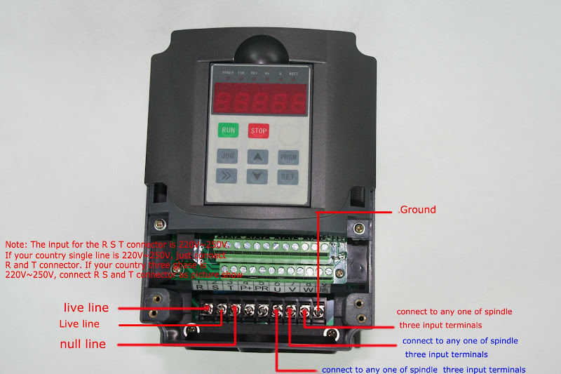
and the vfd.. looks like run the incoming red and black to R &S , green to ground on far right, then just the output of u,v,w to the 1/2/3 terminals in that box on the motor?

0008.jpg
 
Last edited:
To avoid these ads, REGISTER NOW!

Norcal

Well-known member
Joined
Mar 16, 2008
Messages
13,754
You need to lose the drum switch on the mill, VFD's do not like the power interrupted between the motor & the VFD. The drum switch could be wired to control the drive though. The consequences of switching the drives output is letting the magic smoke out, if done one too many times & you have no idea when. :(

Your 240V 1Ø input (220V is obsolete) goes to R & T, the drives 3Ø output connects to U,V,W.

The drive a Chinese no-name model? Most normal models have a 200-230V rating for a 208 -240V supply.
 
OP
C

Cryptic1911

Well-known member
Joined
May 24, 2008
Messages
2,884
Location
Willimantic, CT
Ah ok, so I was thinking right then.. (I had a typo on the R&S, I meant R&T). As for the rotary switch, I was just going to leave it in one position and forget about it, but you're right, someone will probably play with it and let the smoke out. I'll see if I can get another box to just replace that one, or at least gut it out

yeah the vfd is a chinese special.. huanyang 1.5kw / 7amp vfd. Tons of people online use them
 

justanengineer

Well-known member
Joined
Apr 5, 2011
Messages
7,722
Location
Motor City
Ah ok, so I was thinking right then.. (I had a typo on the R&S, I meant R&T). As for the rotary switch, I was just going to leave it in one position and forget about it, but you're right, someone will probably play with it and let the smoke out. I'll see if I can get another box to just replace that one, or at least gut it out

Why gut it or replace it? Those are pretty bullet-proof switches. Just wire it to control the VFD.
 

kevin47

Well-known member
Joined
Jan 30, 2013
Messages
383
Location
Concord California
I'm trying to play catch-up here...How do you reverse motor rotation with this VFD set-up...? I don't know what's going on, sorry...
 
OP
C

Cryptic1911

Well-known member
Joined
May 24, 2008
Messages
2,884
Location
Willimantic, CT
The vfd can reverse the rotation from the buttons on the front of it, or it also allows you to wire in buttons to the rs-485 terminals for start / stop / e-stop (with a braking resistor) / reverse & fwd / as well as a potentiometer to adjust the speed right from a control board that you could mount on the knee or side of the head. That way you can put the vfd in an box on the wall so that you don't get chips and dust in it
 

kevin47

Well-known member
Joined
Jan 30, 2013
Messages
383
Location
Concord California
Great...But, is the only reason to have this VFD is to vary the motor speed or is it a "phase converter", too...The reason I ask is my present shop is three phase out of the wall...But I'm moving to the country and will have to "convert"...I don't need to vary my speeds at all...Just to convert from single to three phase...
 

Norcal

Well-known member
Joined
Mar 16, 2008
Messages
13,754
The switch needs to be removed as-is, but it can be wired to the drive for reversing the motor, there should be nothing between the drive & the motor, the manual should have the info to wire it. (Have heard the tech support is not all that good for the off-breed branded ChiCom VFD's)
 

Doug Arthurs

Well-known member
Joined
Dec 1, 2012
Messages
1,137
Location
Ontario
Great...But, is the only reason to have this VFD is to vary the motor speed or is it a "phase converter", too...The reason I ask is my present shop is three phase out of the wall...But I'm moving to the country and will have to "convert"...I don't need to vary my speeds at all...Just to convert from single to three phase...


You can also use them to provide the third leg for a 3 phase motor.
 

darkk

Well-known member
Joined
Dec 24, 2009
Messages
3,361
Location
Willimantic, Ct.
That VFD converts 220 vac single phase to 220 vac 3 phase. It also varies the frequency to run the motor at different speeds. We were concerned about the extra *4th wire* on the motor itself. As I understood it, the blk/red are hot, the grn is ground and the wht is a nuetral in case you want/need 120 vac for something else. If I'm understanding it all correctly, we can use the blk/red hots and the grn ground eliminate the wht because we have no need for 120 vac and call it a day. The rest we are good on... For those interested, the VFD cost is around $120 shipped with 2 year WTY.
 
Last edited:
OP
C

Cryptic1911

Well-known member
Joined
May 24, 2008
Messages
2,884
Location
Willimantic, CT
You could, but from what I read, using a VFD has cleaner power, so there's no power loss. You don't need to use a VFD to vary the frequency, you could just set it at 60hz and let it run the motors at their rated speeds
 

Cadillac STS

Active member
Joined
Jun 12, 2012
Messages
37
Still shaky on this...I have about 5 machines to switch over...Won't I be better off using a rotory phase converter...?

What I would do is just get a rotary phase converter, run it to all your machines and be done with it. They will run like they were made to run.
 

Cadillac STS

Active member
Joined
Jun 12, 2012
Messages
37
You could, but from what I read, using a VFD has cleaner power, so there's no power loss. You don't need to use a VFD to vary the frequency, you could just set it at 60hz and let it run the motors at their rated speeds

The reason there are 4 wires coming from the motor is because in a 3 phase motor there are 3 coils, if you only power up two it wouldn't be able to start without an added capacitor and then would only have 2/3 the power.

Just use your vfd as per directions and you will have it done.
 
To avoid these ads, REGISTER NOW!

kevin47

Well-known member
Joined
Jan 30, 2013
Messages
383
Location
Concord California
What I would do is just get a rotary phase converter, run it to all your machines and be done with it. They will run like they were made to run.
Thanks for the show of support...That's what I thought would be easiest...Would seem that VFH thing is more of a "static" type converter...I don't know...
 

Cadillac STS

Active member
Joined
Jun 12, 2012
Messages
37
Thanks for the show of support...That's what I thought would be easiest...Would seem that VFH thing is more of a "static" type converter...I don't know...

From what I understand there are 3 ways to go for phase converting from single to 3 phase.

The 3 phase motor has 3 coils and can be run as a motor taking in current but also can be used as a generator producing current when it is turned. The generator idea is important to understand for a rotary phase converter below.

VFD: Electronic conversion from one to three phase. Advantage is it can vary the speed of the motor. Would need a separate one for each machine.

Static phase converter: The 3 phase motor can run on one phase 240 current. It cannot start on one phase though. The static converter box puts a start capacitor on the coil not connected to power so very briefly the motor sees all three powered up and starts. Capacitor goes off after the start and the motor runs one one phase power but only 2/3 power because it is not fully powered on. This can be fine for some applications. Need a separate one for each machine.

Rotary phase converter: This system runs an idler 3 phase motor and generates the third leg of needed power. Works by starting the idler motor with a capacitor like the static. Some people connect up a separate 110 volt motor to spin the idler up to start it. So the idler is now generating your third line to current up your 3 phase system, your box now has coming out of it ground, the two 240 volt lines you already have and now the third line of current. Advantage is you need only one of these for your whole shop depending on if you run more than one machine at once. Can put in a large idler and be able to run multiple machines.

EDIT: I'm not an expert on this but have checked it for my own shop. Anyone can correct me but I think it is correct.
 
Last edited:

theoldwizard1

Well-known member
Joined
Feb 22, 2011
Messages
43,137
Location
SE MI
VFD: Electronic conversion from one to three phase. Advantage is it can vary the speed of the motor. Would need a separate one for each machine.

Only true if you plan on running more than one machine at a time.


VFD are a lot more efficient (consume less power) than rotary converters.
 

Cadillac STS

Active member
Joined
Jun 12, 2012
Messages
37
Only true if you plan on running more than one machine at a time.


VFD are a lot more efficient (consume less power) than rotary converters.

So just get a vfd large enough for your largest motor and it will run the rest just one at a time?
 

larry_g

Well-known member
Joined
Apr 28, 2007
Messages
16,877
Location
oregon
We were concerned about the extra *4th wire* on the motor itself. As I understood it, the blk/red are hot, the grn is ground and the wht is a nuetral in case you want/need 120 vac for something else. If I'm understanding it all correctly, we can use the blk/red hots and the grn ground eliminate the wht because we have no need for 120 vac and call it a day. .

I'm assuming darkk is also working on the same project as the OP. If you look at the wires that are landing on the switch you have blk/red/wht all landing on the switch and all are 1 leg of the three phase. The white in this picture above is not neutral, it is hot and should probably be recolored. Those wires land on the U/V/W terminals of the VFD.

If you were bringing neutral into a 3 phase machine you would have a 5 wire.

lg
no neat sig line
 

kevin47

Well-known member
Joined
Jan 30, 2013
Messages
383
Location
Concord California
Thanks, sounds like rotory converter is probably the way to go for me...Less wiring hassle for one...And I'd want to be able to run more than one machine at a time...While the milling machine takes a pass, I'm de-burring w/3 phase belt sander, etc...

I'm thinking of setting up a sub-panel for the rotory converter...From the single phase panel...Then use that panel the run the machines...Then the 110/220 single phase panel that's already installed, will remain in place for the 110v outlets and small stuff...
 

theoldwizard1

Well-known member
Joined
Feb 22, 2011
Messages
43,137
Location
SE MI
Thanks, sounds like rotory converter is probably the way to go for me...Less wiring hassle for one...And I'd want to be able to run more than one machine at a time...While the milling machine takes a pass, I'm de-burring w/3 phase belt sander, etc...
That could take a pretty big rotary converter ! I don't know how many hours a week you will be using your equipment, but remember the converter consumes power when ever it is powered up, even when all machines are powered down.

EDIT: Quick check on eBay, a 10hp rated rotary phase converter (which will only run a Maximu Group HP of 7.5 ?) costs about $750. It consumes 5A @240V (1.2kw) while idling and should have a 35A breaker.

I'm thinking of setting up a sub-panel for the rotory converter...From the single phase panel...Then use that panel the run the machines...Then the 110/220 single phase panel that's already installed, will remain in place for the 110v outlets and small stuff...
Good idea !

Three phase load centers are expensive, but used ones show up all the time on eBay and probably CL. Make certain you main is no more than what the rotary converter can put out !
 
Last edited:

Cadillac STS

Active member
Joined
Jun 12, 2012
Messages
37
Thanks, sounds like rotory converter is probably the way to go for me...Less wiring hassle for one...And I'd want to be able to run more than one machine at a time...While the milling machine takes a pass, I'm de-burring w/3 phase belt sander, etc...

I'm thinking of setting up a sub-panel for the rotory converter...From the single phase panel...Then use that panel the run the machines...Then the 110/220 single phase panel that's already installed, will remain in place for the 110v outlets and small stuff...

You can buy a complete rotary converter on ebay or just buy the control panel and get a used 5 hp 3 phase motor locally. Can contact the ebay guys and ask any questions as far as what is best for the application. I like the already made panel way that way you know the capacitors are right and connections are right, labelled and safe.

5hp phase converter complete is about $350 on ebay. Or the control panel for $125-135 plus a used or maybe new 5hp 3 phase motor from your Craigslist wanted ad for $50-100 should do the job.
 
Last edited:
OP
C

Cryptic1911

Well-known member
Joined
May 24, 2008
Messages
2,884
Location
Willimantic, CT
It all worked out fine, we got it working. I was concerned about all the settings on the vfd, but it fired right up the first time since apparently I put in the right parameters. It was running backwards, so we had to swap two phases to correct the rotation, but it was a success
 

darkk

Well-known member
Joined
Dec 24, 2009
Messages
3,361
Location
Willimantic, Ct.
That *wht* wire is what kept me confused. The OP is my son so we are working on the same project. I guess I didn't understand at first that in 3 phase there are 3 hots. We ended up using 12/3 so we had 4 wires into the motor box. Since the motor is 1 hp 3.8 amps, we were told #12 gauge would be big enough even over the length we need to run it. We removed the FWD/REV box and replaced it with a metal junction box. We installed a terminal block in the box and connected the wht/red/blk to the existing motor wires just as it appears in the photo and connected the green to the motor head as a ground. Those 4 wires back to the VFD and ran 12/2 into the VFD, then connected the green wires from both the input wire and the motor wire to the *E* terminal in the VFD for a ground back to the service panel. (actually our welder recepticle) because we have to run an extension cord to that end of the shop. The settings for the VFD weren't too confusing, the mill is up and running now. Now all we need to figure out is how to work it, hahahaha....
 

BigGMC

Well-known member
Joined
Jun 6, 2012
Messages
278
Location
Land of Confusion - NY
That *wht* wire is what kept me confused. The OP is my son so we are working on the same project. I guess I didn't understand at first that in 3 phase there are 3 hots. ....

reading through, I was sure thats where the confusiion was, unfortunatly wasn't able to post in time. glad to see you got it figured out.
That original FOR/REV switch would swap two phases to spin the motor in the opposite direction.
 
OP
C

Cryptic1911

Well-known member
Joined
May 24, 2008
Messages
2,884
Location
Willimantic, CT
reading through, I was sure thats where the confusiion was, unfortunatly wasn't able to post in time. glad to see you got it figured out.
That original FOR/REV switch would swap two phases to spin the motor in the opposite direction.

Technically it would, but apparently vfd's don't like it when you interrupt the power between it and the motor, so they want you to wire directly from the vfd to motor, and then use the vfd control panel, or a remote mounted switch back to the vfd's remote control terminals to actually swap the rotation. That way it will spin down the motor, then spin it back the other way properly, and not damage the vfd in the process
 

BigGMC

Well-known member
Joined
Jun 6, 2012
Messages
278
Location
Land of Confusion - NY
Technically it would, but apparently vfd's don't like it when you interrupt the power between it and the motor, so they want you to wire directly from the vfd to motor, and then use the vfd control panel, or a remote mounted switch back to the vfd's remote control terminals to actually swap the rotation. That way it will spin down the motor, then spin it back the other way properly, and not damage the vfd in the process

yeah, i understood about the vfd, was just saying that's how the unit reversed originally (with the switch)

carry on! :rocker:
 
To avoid these ads, REGISTER NOW!
Top Bottom