American Locomotive
Well-known member
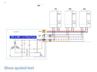
The inverters are operating properly and are synchronized in 3 phase operation. The inverters are displaying their own phase to neutral voltage, NOT their phase-to-phase voltage.
As someone elese mentioned, 208*1.73 = 360v, so the math checks out.
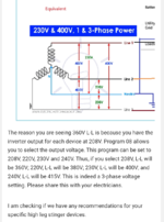
In, Europe, 400v phase-to-phase 3phase with a 230v phase-to-neutral single phase service is super common.
To get 230v 3 phase out of these inverters, you will need to set them to 132v (230/1.73=132).
If you want to run single phase loads as well, you will need to set them to 120v. The problem is your 3 phase voltage wil drop to 208. Your pump might be okay on 208v, but you will need to verify.
Also keep in mind you will only get about half of the inverter's rated power at 208v vs 400.
As someone elese mentioned, 208*1.73 = 360v, so the math checks out.
In, Europe, 400v phase-to-phase 3phase with a 230v phase-to-neutral single phase service is super common.
To get 230v 3 phase out of these inverters, you will need to set them to 132v (230/1.73=132).
If you want to run single phase loads as well, you will need to set them to 120v. The problem is your 3 phase voltage wil drop to 208. Your pump might be okay on 208v, but you will need to verify.
Also keep in mind you will only get about half of the inverter's rated power at 208v vs 400.