To avoid these ads, REGISTER NOW!

3 way confusion

andyvh1959

Well-known member
Joined
Feb 15, 2020
Messages
2,617
Location
Green Bay WI
Like, who takes the lead?

No, no, not that. My house was built in 1973. I'm making repairs of some rotted framing at the front door which included pulling wires back to do the framing. My front door has two light switches, a single switch to control the outside yard lights, and another swirch that did nothing. When I opened the box at the front door I found the left is a three way switch, which I have now traced to a three way switch up near the kitchen entrance. Plus there are two cover plates in the front atrium ceiling with no lights wired to them. I need to check but I'm pretty sure the 3way swirches would control lights in the front atrium wired in at the now unused cover plates.

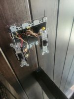
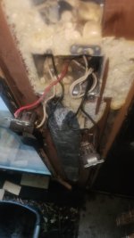
I know a 3way switch is wired with the neutral not in the switched circuit, with line/power coming to one 3way and a line transfer to the other 3way, Then the red and black wires go across the load terminals of the 3way swirches. Look at the attached pic (left one). I think whoever wired the house in 1973 used the white between the 3ways as the line transfer, but it is not colored black or red to indicate such. I traced the wiring with continuity on the red, black and white to the 3way from the front entrance to the triple box with two switches, confirming the 3way switch on the left is the same circuit as the 3way at the front door.

To be wired correctly I should mark the current white wire with black tape to indicate it as the line trasfer between the 3way switches correct? Then confirm line feed at the box near the kitchen to make sure I don't have two line feeds going to the 3way circuit, and confirm the neutral at the box near the kitchen is not in the 3way circuit The left pic is the front entrance as I found it when I started the repairs, I did no wiring there. The right pic is a triple box I moved from the other side of the wall when I built the pantry in the kitchen.
 

Attachments

  • 20260814_103350.jpg
    20260814_103350.jpg
    260.4 KB · Views: 24
  • 20260826_140759.jpg
    20260826_140759.jpg
    650.2 KB · Views: 24
To avoid these ads, REGISTER NOW!

75gmck25

Well-known member
Joined
Jul 21, 2014
Messages
1,348
Location
Alexandria, VA
You are on the right track, but three-way switches can be wired differently, based on power first to either the switch or the fixture, whether the light is at the end, light in the middle, etc.

I would recommend opening up the fixtures you think it controls, and then use some long test leads and a multi-meter between the light fixtures and the switches to figure out how the wires are run. Once you know what you have it should be easy to figure out any rewiring or wire marking needed.
 

wyliesdiesels

Well-known member
Joined
Aug 14, 2012
Messages
20,241
Location
Modesto, CA
what youre calling line transfer is actually called a traveller.

you should have 2 travellers between 2 3-way switches. they can be any color and if white conductor is used, should be taped another color. typically white would be used as the neutral between the switches to feed the fixture(s). but sometimes people get confused and do all sorts of wonky ****

one switch will have incoming power from breaker panel on the black screw. other switch has power out to the fixture(s) on the black screw. travellers go on brass. neutral doesnt touch switches.
 

75gmck25

Well-known member
Joined
Jul 21, 2014
Messages
1,348
Location
Alexandria, VA
"you would have to run extra wires if the power went to the fixture first"
You are probably correct, since for standard wiring schemes you would need four wires between the two switches to make it work.
However, it is possible to make it work with all 14/2 and 14/3 by powering the fixture first, and then running your cable to each switch. I don't think the OP has opened up the boxes for the two fixtures yet, so further "surprises" are possible.
1787786873080.png
 

sparky 1971

Well-known member
Joined
Oct 9, 2018
Messages
8,127
Location
Central Iowa
There are way too many ways to make a three way set up work for an interweb diagnosis and since I'm going on nothing but pictures instead of standing in front of the switches with a meter, I'll admit to being confused. A bunch of spray foam needs cleaned out of the box in the first picture because, while anything is possible, I doubt I see what I think I'm seeing. In the second picture it looks like the blacks from the 14/3's are on the wrong switches but it could very well be the angle of the photo. I've figured out some goofy three way wiring, and if this configuration worked before, it can work again but it's going to require cleaning up the mess and better pictures from straight on instead of angled down. And maybe a little help from the OP with a meter and continuity tester.
 

sparky 1971

Well-known member
Joined
Oct 9, 2018
Messages
8,127
Location
Central Iowa
you would have to run extra wires if the power went to the fixture first
I'll throw this in just go go along with the title of this thread because it happens. The stupid MF'r that wired the addition at my house in the 80's took the power to the living room ceiling fan and controlled both fan and light from three ways. 14/2 in and out to something else for power. The hot end of the three ways has a 14/3 and 14/2 travellers with the black of the 14/3 being the hot for both switches, travellers are red and white with black and white (no red, it's 14/2) for the other switch. Two 14/3's going to the other set of switches; the one for the light has black and white travellers and red switch leg, the fan has red and white travellers with a black switch leg. And the dumb ******* stuffed all of that **** in a pancake box. I learned all of that one afternoon when I got home to find that my wife, who has heard me complain about how much I hate hanging ceiling fans hundreds if not thousands of times, decided to surprise me by buying a new fan and hanging it herself. I was surprised all right, she took every joint in the box apart and didn't know what to do with all those wires.

There have been two times that I had to stop and draw a picture of what I had in order to figure out how to get the three ways to work and that was one of them. The other wad the first of two times I ran into a California/Chicago/Carter three way, hopefully shown below. I couldn't figure out how it worked until I saw it on paper and it's still confusing to this day even though I know it "works".

 
Last edited:
To avoid these ads, REGISTER NOW!
OP
A

andyvh1959

Well-known member
Joined
Feb 15, 2020
Messages
2,617
Location
Green Bay WI
I agree about the 2nd pic analysis that the wiring there at least is wrong (my doing). So I need to spend some time doing continuity checks with my meter to really figure out what is where.

I dug out all the foam insulation and in fact removed the box at the front door, because, well the dumbasses that built this house simply carved out a signifiant chunk of the 2x4 vertical support to fit a 2-gang recessed box, which is also the lockse side of te front door. I ripped out that box, and while I had the wall jacked up (4-ton bottle jack) so I could replace the fully rotted sill plate and 3" rotted off the 2x4 wall studs, I installed a new sill, scabbed in new wood to the rot trimmed wall 2x4s and installed another new 2x4. A new 2-gang box is mounted on the face of the cedar trim, to which I added a small shelf to fit around the box.

Hope I neven meet the ******* contractors that built this house because I don't think I'll be able to hold my tongue. I'm no house builder or contractor (though I have built three garages) but the amount of piss poor work and shortcuts in the construction of this house just pisses me off.
 

mm08822

Well-known member
Joined
Jan 13, 2012
Messages
6,256
Location
NJ
I'll throw this in just go go along with the title of this thread because it happens. The stupid MF'r that wired the addition at my house in the 80's took the power to the living room ceiling fan and controlled both fan and light from three ways. 14/2 in and out to something else for power. The hot end of the three ways has a 14/3 and 14/2 travellers with the black of the 14/3 being the hot for both switches, travellers are red and white with black and white (no red, it's 14/2) for the other switch. Two 14/3's going to the other set of switches; the one for the light has black and white travellers and red switch leg, the fan has red and white travellers with a black switch leg. And the dumb ******* stuffed all of that **** in a pancake box. I learned all of that one afternoon when I got home to find that my wife, who has heard me complain about how much I hate hanging ceiling fans hundreds if not thousands of times, decided to surprise me by buying a new fan and hanging it herself. I was surprised all right, she took every joint in the box apart and didn't know what to do with all those wires.

There have been two times that I had to stop and draw a picture of what I had in order to figure out how to get the three ways to work and that was one of them. The other wad the first of two times I ran into a California/Chicago/Carter three way, hopefully shown below. I couldn't figure out how it worked until I saw it on paper and it's still confusing to this day even though I know it "works".

I ran into that once. Had me scratchin me head saying WTF!!!???
IIRC, Hot wire only from a single pole switch box in bedroom was sent through a piece bx jacket into the 3way switch box on the other side of the wall. 2 wire cable carried the travelers back to the ceiling outlet.

I dont even remember if they were on the same branch cb. Maybe/dunno.

All that stupidity to save 1 conductor!!!????
 

sparky 1971

Well-known member
Joined
Oct 9, 2018
Messages
8,127
Location
Central Iowa
I ran into that once. Had me scratchin me head saying WTF!!!???
IIRC, Hot wire only from a single pole switch box in bedroom was sent through a piece bx jacket into the 3way switch box on the other side of the wall. 2 wire cable carried the travelers back to the ceiling outlet.

I dont even remember if they were on the same branch cb. Maybe/dunno.

All that stupidity to save 1 conductor!!!????
Was it knob and tube? Both of mine were and both were for the stair lights; the first between the first and second floor of a two story house and the second was between the main level and the basement. On the second house I just kept moving the wires around on the switch that the owner had tried to replace the day before until it worked the way I wanted it to and got outa there.
 

mm08822

Well-known member
Joined
Jan 13, 2012
Messages
6,256
Location
NJ
Was it knob and tube? Both of mine were and both were for the stair lights; the first between the first and second floor of a two story house and the second was between the main level and the basement. On the second house I just kept moving the wires around on the switch that the owner had tried to replace the day before until it worked the way I wanted it to and got outa there.
Nope, bx. Maybe from late 40s or 50s.

I had to open up everything and draw it out. Checked it 2x. Said WTF and put it back as it was. All I was doing was adding a ceiling outlet in bedroom.
 
OP
A

andyvh1959

Well-known member
Joined
Feb 15, 2020
Messages
2,617
Location
Green Bay WI
As I posted my house was built in 1973, "modern" wiring in my book and most of what I've found was simply chitty work done by the "master electrician" who I was told was the uncle of the people that had the house built. He was a master of sloppy work I'll say that. I found live unconnected wires under both decks. Loose connections in the main panel. Doubled wires on the black connection at a few breakers. Whatever wire was pulled into the main panel, even if it was five feet long, was all doubled up into the panel making it look like a spider web after a tornado went through. Built my shop at this house back in 2019 and wired it all myself including a subpanel for 220v. Redid the main panel to clean up the mess.

My previous house (bought in 1995) dated to the 1920s, but was moved onto a new foundation, was totally rewired to 1990 standards, and well done. But as I remodeled some rooms I added outlets and electrical features. Built a 7-car garage for that one and did all the wiring for that build, including a sub panel for 220v in the shop.

My 1st house I bought when I was 21 years back in 1978 old, 1938 vintage little 1000 sq-ft house and needed lots of work. 60 amp serivce and four fuses in the main panel. Lots of oldswitches and 16ga wiring with cotton braided insulation on it. So I rewired the entire house from the meter in, uped it to 100 amp service and installed a 24 breaker main panel. Built a 16x20 garage for that house and wired it all myself.
 
To avoid these ads, REGISTER NOW!
Top Bottom