So recently I moved into a new house and I'm trying to figure out some of the electrical wiring done by the electrician/plumber that was in charge of the electrical installation.
So far, with the things discovered, I'm really feeling lucky I don't have water coming out of the wall sockets.
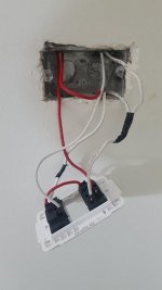
This is one of the latest discoveries... I have a 3 way switch on each side of stairs... One on the bottom, one on the top. I wanted to connect an additional switch for another light on the hallway, which would be separate from the 3 way circuit.
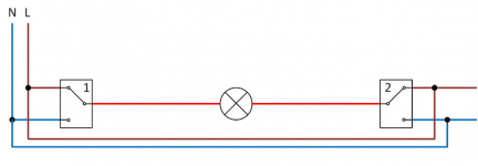
I did a quick sketch of the wiring I found... Traveler legs on the 3 phase switch are connected to phase and neutral on both sides and the light fixture is between both commons.
So is this guy a genius or should I never let him touch another wire... I'm definitely on the latter side...

So far, with the things discovered, I'm really feeling lucky I don't have water coming out of the wall sockets.
This is one of the latest discoveries... I have a 3 way switch on each side of stairs... One on the bottom, one on the top. I wanted to connect an additional switch for another light on the hallway, which would be separate from the 3 way circuit.
I did a quick sketch of the wiring I found... Traveler legs on the 3 phase switch are connected to phase and neutral on both sides and the light fixture is between both commons.
So is this guy a genius or should I never let him touch another wire... I'm definitely on the latter side...


")