Sorry for the delayed reply; I was "down" with some weird stomach virus or similar for nearly a week, and am just now starting to catch up. Suffice it to say, a few days ago I would have given my eye teeth to merely "feel like utter ****". Then, on top of that, the Forum itself has apparently been having "issues".
And how did the calculated lighting performance change when you did that?
Not really. If you look down to the lower part of the page, where the fixture type and its specs are noted, there are fields to specify, among other things, the "Suspension Height". You can also do at least a rough approximation of old, degraded tubes by simply lowering the default lumen output by 10-20%, a field for which is also in that same section of the page.
It probably does. But this misses the point that you just don't need it. If you use a modicum of common sense when laying out your lights, anything beyond a crude "sanity check" is simply unnecessary -- and as you have so spectacularly illustrated in this thread, it can actually be misleading.
This is one of the reasons why I keep cautioning you to not put so much blind faith in a lighting calculator, or any over-simplified "single figure of merit", such as the average illumination per ft.^2.
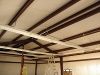
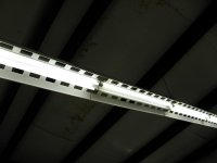
Based on the layout you showed, vis-a-vis the distribution pattern of typical fluorescent tube/fixture, it was reasonable to presume that
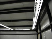
most of the light from each of those fixtures would be dispersed perpendicular to the tubes, as opposed to parallel to the tubes. So, with the fixtures arranged in two rows, with each fixture rather tightly-spaced (broadside) to the next one, yet leaving a relatively large gap between the two rows themselves... Well, that "banding" effect seemed pretty likely. That said, the various room surfaces MAY be sufficiently reflective to at least partially ameliorate the effect; and so too, you may just be accustomed to it.
{re: layout/distribution is more important that arbitrary lumen levels}
Your garage is NOT a "world class aircraft manufacturing facility". And more importantly, from a lighting perspective the two applications don't necessarily have much in common.
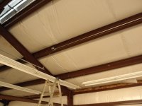
OK, that's new information (I think). I'm not going to dig back through all the old posts at this point; but I'd gotten the distinct impression we were talking about a relatively flat ~10-foot ceiling. Having a cathedral ceiling has some impact on the style of fixtures you would choose; but it doesn't really obviate my previous comments. And the limiting factor is still the 10-foot height at the lowest points.
Well, perhaps not THAT software. But again, don't sweat that.
Better to get it (at least nearly) right the first time.
{re: simplistic lighting calculators are merely "sanity checks"}
Well... "mostly", perhaps.
Did you not read/understand the explanations I posted SEVERAL times as to why 8-foot fixtures are by definition less-than-ideal?
{re: yet another of those explanations...}
That may be slightly related; but it's not really what I'm talking about.
The
MAIN issue is to have enough flexibility in terms of how many (and exactly WHICH) tubes get turned on at any given moment that you will have the best chance of being satisfied with reduced-intensity lighting more of the time. If, because there are huge/severe gaps in the coverage pattern at (let's call it) "Stage 1", you are too often tempted/forced to go to "Stage 2" just to fill in that gap, then you will have defeated the purpose (and written off the benefit) of multi-stage lighting.
{SIGH}
You are
STILL thinking in terms of "zoning", as opposed to "intensity control". I've tried several times to get the latter concept across to you, apparently without success. So I give up.
For the functionality you describe, Insteon controllers are just the ticket.