To avoid these ads, REGISTER NOW!

3amp fuse keeps blowing

chrishall0604

Member
Joined
Sep 25, 2023
Messages
9
I was changing out my contactor (coil was bad) when my screwdriver touched the low voltage connection and the metal part of the contactor at the same time causing it to spark. I unfortunately don’t have a disconnect switch and was relying on someone inside to cut the breaker off (wrong breaker was flipped and I didn’t verify with my meter before I started 🤦‍♂️). But here we are, it blew the 3amp fuse and now when I replace the fuse it immediately blows. No wires are bad, new contactor installed, and a fairly new capacitor.

I checked the board with my meter and it seems to be transmitting power.


Im assuming the board is burned up now? Any suggestions before I buy the 250$ circuit board.
 
To avoid these ads, REGISTER NOW!

RPH

Well-known member
Joined
Dec 17, 2006
Messages
4,190
Location
Michigan Thumb
Pictures would help off both sides of said board. Without those, ya you’re right board must be bad! Pics first, let us help.
 
OP
C

chrishall0604

Member
Joined
Sep 25, 2023
Messages
9
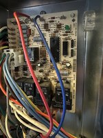
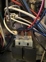
Here are some pictures. Let me know if you need better ones. I don’t see any obvious burn marks on the board but I could be wrong.
 

Attachments

  • IMG_4547.jpeg
    IMG_4547.jpeg
    707.7 KB · Views: 46
  • IMG_4546.jpeg
    IMG_4546.jpeg
    778 KB · Views: 38
  • IMG_4548.jpeg
    IMG_4548.jpeg
    587.7 KB · Views: 35
  • IMG_4549.jpeg
    IMG_4549.jpeg
    751.4 KB · Views: 57

RPH

Well-known member
Joined
Dec 17, 2006
Messages
4,190
Location
Michigan Thumb
Nothing stands out from these shots. Without seeing the backsides of boards damage is not always apparent. Can you indicate the high voltage to low voltage cross connection occurred?
Model # and prints are always appreciated.
 
OP
C

chrishall0604

Member
Joined
Sep 25, 2023
Messages
9
Check the back side of the board also.

Is there a wiring diagram ?
Unfortunately there isn’t a wiring diagram. It’s pretty old not to much to go off of. The part number for the replacement board is:

S1-031-01932-002
 
OP
C

chrishall0604

Member
Joined
Sep 25, 2023
Messages
9
Nothing stands out from these shots. Without seeing the backsides of boards damage is not always apparent. Can you indicate the high voltage to low voltage cross connection occurred?
Model # and prints are always appreciated.
Here is the back. Y’all were right, definitely a burn mark on the back.

I’m not the savviest when it comes to electrical just enough to get me in trouble I guess. What do you mean by high and low cross connection?
 

Attachments

  • IMG_4550.jpeg
    IMG_4550.jpeg
    889.2 KB · Views: 52

RPH

Well-known member
Joined
Dec 17, 2006
Messages
4,190
Location
Michigan Thumb
Ok, so what’s the level of expertise and tooling for this job.
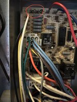
The areas I marked I would look closely at. In a situation where high voltage was introduced into low voltage circuitry I look for solder splatters, burnt traces, and hot spots.
I believe the area you marked might be a relay on the other side. If that is the case then the freewheeling diode on the coil could have shorted. But without knowing your level of expertise it’s hard to recommend component level repairs.IMG_4375.jpeg
 
OP
C

chrishall0604

Member
Joined
Sep 25, 2023
Messages
9
Ok, so what’s the level of expertise and tooling for this job.
The areas I marked I would look closely at. In a situation where high voltage was introduced into low voltage circuitry I look for solder splatters, burnt traces, and hot spots.
I believe the area you marked might be a relay on the other side. If that is the case then the freewheeling diode on the coil could have shorted. But without knowing your level of expertise it’s hard to recommend component level repairs.IMG_4375.jpeg
Thank you! Honestly I’ve never had any luck repairing components on a circuit board. But if it’s definitely a bad board I can certainly swap the components from one to the other lol.

But the area I marked up should be this area if you were curious or if that helps at all. And now after seeing the back, you can really tell the discoloration on the front side.
 

Attachments

  • IMG_4551.jpeg
    IMG_4551.jpeg
    593.6 KB · Views: 40

mm08822

Well-known member
Joined
Jan 13, 2012
Messages
6,045
Location
NJ
I'd go for picking off the identified solder splats. Looks like they could have connected a few traces.

See what component is on the other side of the missing solder.....
1695671896450.png

Or is the problem occurring between the missing solder connection and the "square soldered" connection??
 
Last edited:
  • Like
Reactions: RPH
OP
C

chrishall0604

Member
Joined
Sep 25, 2023
Messages
9
Those big old blue resistors are going to get warm. That’s why they’re so big.
Ok well that makes sense as to why it’s discolored in that area. The other small spot you pointed out seems to just by Knicks in the coating on the back. Could I have shorted a wire out and need to just replace that? Probably a dumb question but I guess that answers your question about my level of expertise lol
 
To avoid these ads, REGISTER NOW!

RPH

Well-known member
Joined
Dec 17, 2006
Messages
4,190
Location
Michigan Thumb
If you shorted a wire you should see carbon marks from arcing. That should be obvious. Board traces are a bit more difficult to do.
Mm08822 has a good point. But don’t be afraid to scratch the board. Just don’t cut traces!
One of the first things to do is clean solder splatters or look alike to determine what it is you’re dealing with.
Burnt traces usually are apparent.
 
OP
C

chrishall0604

Member
Joined
Sep 25, 2023
Messages
9
I’m going to have to call someone lol. I’ve looked this thing over 100 times now and I don’t see any stray Sadler marks or splatter. I’m guessing I burnt up a component or two. But I appreciate you guys for responding and trying to help! I definitely learned some things from the conversation and also learned what not to do lol
 

Sinatra

Well-known member
Joined
Apr 22, 2013
Messages
117
I don’t see anything obvious on the circuit board either. Does the fuse blow immediately when you install it or when the thermostat calls for cooling? Before you the condemn the control board, disconnect the two low voltage wires at the outside unit. Make sure the red and white wires have tape or nuts on them. They are exposed in photo #4. Then try a new fuse.
 
OP
C

chrishall0604

Member
Joined
Sep 25, 2023
Messages
9
I don’t see anything obvious on the circuit board either. Does the fuse blow immediately when you install it or when the thermostat calls for cooling? Before you the condemn the control board, disconnect the two low voltage wires at the outside unit. Make sure the red and white wires have tape or nuts on them. They are exposed in photo #4. Then try a new fuse.
It blows immediately when I switch the power on. I’ll definitely try disconnecting the low voltage wires outside before plugging a new fuse in. Thank you for that suggestion that’s one thing I didn’t try. If that does work, or Atleast doesn’t blow the fuse, what would that narrow the problem down to? Yeah I had the caps off at the time I took the pictures, they’re back on now.
 

Sinatra

Well-known member
Joined
Apr 22, 2013
Messages
117
The red or white wires could be touching the metal cabinet and grounded or the new contractor coil could be bad.
 
OP
C

chrishall0604

Member
Joined
Sep 25, 2023
Messages
9
The red or white wires could be touching the metal cabinet and grounded or the new contractor coil could be bad.
Well hopefully the new contactor isn’t bad it was just delivered this morning. I’ll be giving your suggestion a try tomorrow evening when I got home. I’ll definitely let you know what the outcome is.
 

ericm

Well-known member
Joined
Apr 17, 2016
Messages
1,963
Location
Southern Oregon
I forget the exact spec for contactor coil resistance (it's something like 5-15 ohms) but if it's too low the fuse will blow.
 

BrandonV

Well-known member
Joined
Jun 9, 2023
Messages
4,030
Location
Arizona
I'd look at the resistance on the reversing valve, contactor and any other thing equipped that pulls a load (coil heater/etc.).

Board looks fine visually.
 

pcmeiners

Well-known member
Joined
Aug 13, 2009
Messages
7,952
Location
In the only town in Pennsylvania, Bloomsburg.
Though there are a number of hot resistors, that can be perfectly normal, the "warm" spots are within normal, abnormal spots are usually much darker . Using OHM's law, take a ohm reading on the contactor coil, or the total ohms... with OHM's law calculate the current draw of the coil, or the total of the line, or you may have a short.
 
To avoid these ads, REGISTER NOW!
Top Bottom