nwav8tor
Well-known member
OK guys, I've searched the forum and found lots of info on the subject, but I still want to confirm my wiring plans for a new compressor.
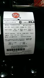
It's a 3 HP, 60 gallon model with a 15 amp rating on the motor. There is a overload reset button on the motor itself. The manual says it must be connected to a 230V single phase outlet (6-30R) having a capacity of 20 amps. It will be located no more than 10' from an existing 14-30R receptacle supplied by a 3' 10-3 NM wire run to the garage sub-panel and its 30A double pole breaker.
1) Since the motor has overload protection itself, can I just utilize the existing 30A breakers as long as the wiring between the AC and the outlet is sized appropriately, or should I change the CB out to a 20A double pole to limit current available to the motor?
2) Should #10 wire be used between the AC and the receptacle if I change to a 6-30R and use a 6-30P? I think #12 might be a bit small considering the NEC 125% motor wiring requirement and potential voltage drop.
3) If I go the hardwire route, can I remove the existing receptacle and use #10 wire in flex conduit to run between the AC and the junction box that had the receptacle in it? What diameter conduit would be required for three #10 wires?
4) Is it OK to just cut the uninsulated end of the unused neutral wire of the existing 10-3 NM after removing the 14-30 receptacle and cap it with a wire nut to leave in the existing junction box?
Thanks for your help...
Paul