This is an out growth of the 60 year old traffic control sign thread. I was offended by the $50 controller to $10 in parts. Robert Haas challenged me to make on for him, ( which I will do) but I have received a good number of private messages so there is enough interest to justify a thread.
To do this for ~$5 you have to buy the parts direct from China. Depending on where you live that means a 30-90 day lead time for parts to show up. I personally have a 5-10% DOA rate. All the sellers have been great and issued prompt refunds or sent new parts. However that increases lead time and if you are new to electronics and don't know how to trouble shoot that can be incredibly frustrating.
I also buy a lot of parts from Adafruit. Local US company making a lot of boards in NYC (with Chinese chips, but there is no way around that) . You pay a large premium to order from them, but their shipping is incredibly fast and I have never had a DOA part. They also have really great tutorials and support for their products so if I need parts quickly or need something to work I have not problem paying the price
Parts:
Adafruit
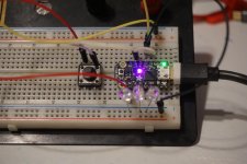
Trinket M0 -8.95.
Relay -$9.95 x3
Chinese:
Arduino -$1.68 + .68 shipping
Relay - $.69+.$.73shipping x3
or
Relay Board -$1.95 +$2.59 shipping
Optional, but will save you running an extra wire
Power supply $.66 +.$73 shipping.
It is amazing that our little trade war has doubled prices in the last 6 months, but still ridiculously cheap.
Personally I would spend the money to by the M0 from Adafruit, and the relay and power supply from Aliexpress. You will also need a button and some wire.
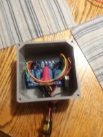
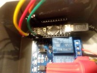
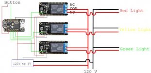
Next up Wiring:
To do this for ~$5 you have to buy the parts direct from China. Depending on where you live that means a 30-90 day lead time for parts to show up. I personally have a 5-10% DOA rate. All the sellers have been great and issued prompt refunds or sent new parts. However that increases lead time and if you are new to electronics and don't know how to trouble shoot that can be incredibly frustrating.
I also buy a lot of parts from Adafruit. Local US company making a lot of boards in NYC (with Chinese chips, but there is no way around that) . You pay a large premium to order from them, but their shipping is incredibly fast and I have never had a DOA part. They also have really great tutorials and support for their products so if I need parts quickly or need something to work I have not problem paying the price
Parts:
Adafruit
Trinket M0 -8.95.
Relay -$9.95 x3
Chinese:
Arduino -$1.68 + .68 shipping
Relay - $.69+.$.73shipping x3
or
Relay Board -$1.95 +$2.59 shipping
Optional, but will save you running an extra wire
Power supply $.66 +.$73 shipping.
It is amazing that our little trade war has doubled prices in the last 6 months, but still ridiculously cheap.
Personally I would spend the money to by the M0 from Adafruit, and the relay and power supply from Aliexpress. You will also need a button and some wire.
Next up Wiring:
Last edited:

") I'm familiar with GIMP....been using it for years .
I'm familiar with GIMP....been using it for years .


 AWESOME