To avoid these ads, REGISTER NOW!

5kW Heater - Am I losing it?

freebo86

Well-known member
Joined
Jun 19, 2015
Messages
362
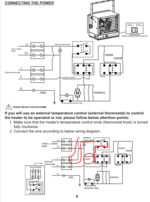
So I’ve got a 5kW DynaGlo heater. The unit has a switch on the rear of it to use external thermostat or use the built it (dial knob). I want this thing wired to the external thermostat - based on the diagram that’s within the manual it appears to me that they call for a double pole thermostat but no mater how I look at this wiring I don’t seem to understand how is a 4wire thermostat (2pole ) wired to setup. Because based on the schematic it appears to me all they are switching is the L1 once the units rear switch is set to use the “external thermostat”. Can someone tell me what I’m doing here and if I’m not understanding this diagram properly.

With the switch on external L1(RED) stops at selector switch after the internal stat. L1 goes out to the external stat and comes back through the switch to the heaters (red) and the selectable wattage heaters (blue) and returns to L2 purple.

In other words, I got L1 coming out through #1 on heater into the tstat connecting to “Line”, then going out back through Load into terminal #2 on heater.
18D4E08F-0866-4FCF-AC1C-80AE2E2813E4.jpeg

How do I use a double pole thermostat in this scenario without putting it infront of L1 & L2 at the main incoming connection. Can you connect the “Line” and “3” on the double pole thermostat and also tie together the“Load” and “4”?
 
Last edited:
To avoid these ads, REGISTER NOW!

Bert_

Well-known member
Joined
Dec 24, 2016
Messages
9,777
Location
NW Iowa
They show a double pole with both contacts wired in series. This is sometimes done to achieve a voltage rating. No reason you can't use an appropriately rated single pole.
 
OP
F

freebo86

Well-known member
Joined
Jun 19, 2015
Messages
362
They show a double pole with both contacts wired in series. This is sometimes done to achieve a voltage rating. No reason you can't use an appropriately rated single pole.

so can I take a regular double pole thermostat and basically wire the leads in series? Reducing it from 4 wires down to 2? I want a double pole thermostat to get a true “off” setting.

In other words connect “line” and “3” together which are red which will also be connected to my L1 incoming. Ie. #1 from the heater terminal And connect “load” and “4” together which will go to back out to the #2 on the heater terminal.
 
OP
F

freebo86

Well-known member
Joined
Jun 19, 2015
Messages
362
I don't understand what the issue is with just wiring the external thermostat the way they show ?

Pardon my inexperience, but I see 1 wire coming into the external thermostat and 1 wire leaving it.

The double pole thermostat has 4 wires.. Line, Load, #3 and #4..

Does Line and #3 get tied together and Load & #4 get tied together? Thus, basically having 2 wires on the double pole thermostat which has L1 incoming (from Terminal Station #1) to Line&#3, and Load&#4 leaving out to Terminal Station #2 on the Heater.
 

pl_silverado

Well-known member
Joined
Jul 1, 2005
Messages
2,033
Location
West Bradford, PA
So your trying to wire it to an external line voltage stat…

Drawing 21 amps, I would just get rid of their thermostat and wire it to a AUBE RC840T-240 and use whatever 24v thermostat you want. Get rid of all the other switches too and just have all the elements come on at the same time.
 
OP
F

freebo86

Well-known member
Joined
Jun 19, 2015
Messages
362
So your trying to wire it to an external line voltage stat…

Drawing 21 amps, I would just get rid of their thermostat and wire it to a AUBE RC840T-240 and use whatever 24v thermostat you want. Get rid of all the other switches too and just have all the elements come on at the same time.

Yes, exactly, trying to use a Line Voltage thermostat.

Appreciate the suggestion and a low voltage thermostat idea sounds great, but I am trying to get this as simple and cost effective as possible.
 

BillK

Well-known member
Joined
Aug 24, 2006
Messages
9,365
Location
Beautiful Southern Maryland
Pardon my inexperience, but I see 1 wire coming into the external thermostat and 1 wire leaving it.

The double pole thermostat has 4 wires.. Line, Load, #3 and #4..

Does Line and #3 get tied together and Load & #4 get tied together? Thus, basically having 2 wires on the double pole thermostat which has L1 incoming (from Terminal Station #1) to Line&#3, and Load&#4 leaving out to Terminal Station #2 on the Heater.
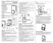
I am not sure if they are showing all of the wiring for the thermostat. What model thermostat is it ? Take a look at the instructions for this one which is exactly the one I would be using:


pl_silverado

Well-known member
Joined
Jul 1, 2005
Messages
2,033
Location
West Bradford, PA
Yes, exactly, trying to use a Line Voltage thermostat.

Appreciate the suggestion and a low voltage thermostat idea sounds great, but I am trying to get this as simple and cost effective as possible.

The AUBE is $60 on Amazon. That’s as cost effective as your money can be when it comes to controls wiring.

The alternative way to go would be a separate 24v transformer and a 240v contactor with 24v coil, which would do the same as the AUBE for $300+ if you get a good one.

If you want I can send you a basic 24v Honeywell stat for the cost of shipping.
 
OP
F

freebo86

Well-known member
Joined
Jun 19, 2015
Messages
362
The AUBE is $60 on Amazon. That’s as cost effective as your money can be when it comes to controls wiring.

The alternative way to go would be a separate 24v transformer and a 240v contactor with 24v coil, which would do the same as the AUBE for $300+ if you get a good one.

If you want I can send you a basic 24v Honeywell stat for the cost of shipping.

Appreciate the offer but I'd just like to stick to the line voltage thermostat.

I am not sure if they are showing all of the wiring for the thermostat. What model thermostat is it ? Take a look at the instructions for this one which is exactly the one I would be using:


Its a Dimplex, TD322W

1672761628619.png
 

BillK

Well-known member
Joined
Aug 24, 2006
Messages
9,365
Location
Beautiful Southern Maryland
Its a Dimplex, TD322W
The instructions are confusing but it looks like they are using a separate power feed for some reason. Thats the two wires coming in at the top. Looks basically the same as the one I linked to. There might be a relay in it of some type. Very hard to tell from their diagram but why dont you just hook it up like it is supposed to be ? I know it involves running another circuit but sometimes you have to do what you have to do to get things the way you want them :)

Why dont you just call them and ask them to make sure ?????
 

pl_silverado

Well-known member
Joined
Jul 1, 2005
Messages
2,033
Location
West Bradford, PA
Your overthinking it, and the extra ******** switches they add aren't helping the confusion. Looks like everything in that heater is 240v, fan motor and elements. Abandon all their ****, Wire L1 to one side of fan motor, and each element, other side to high limit switch, then from high limit switch to l2. now you have a working heater with fan and all elements running without any of their stats or switches. Add your line voltage stat wherever you want and run the appropriate wires to it. Its a simple circuit, and at only 5000w i don't see why it needs three switches to begin with.
 
OP
F

freebo86

Well-known member
Joined
Jun 19, 2015
Messages
362
The instructions are confusing but it looks like they are using a separate power feed for some reason. Thats the two wires coming in at the top. Looks basically the same as the one I linked to. There might be a relay in it of some type. Very hard to tell from their diagram but why dont you just hook it up like it is supposed to be ? I know it involves running another circuit but sometimes you have to do what you have to do to get things the way you want them :)

Why dont you just call them and ask them to make sure ?????

I tried calling, support is non-existent. What do you mean by run another circuit?

External Thermostat Lines 1 and 2 is not a new circuit. The main 240V incoming comes in at the top of the diagrams as L1 and L2, L1 get's switched and goes back out through Line 1 that goes towards the external thermostat box. This is where I am confused. I have 1 wire coming into a 4 wire thermostat - I know load is going back out towards terminal #2. But what happens to the other 2 wires in this thermostat...

Your overthinking it, and the extra ******** switches they add aren't helping the confusion. Looks like everything in that heater is 240v, fan motor and elements. Abandon all their ****, Wire L1 to one side of fan motor, and each element, other side to high limit switch, then from high limit switch to l2. now you have a working heater with fan and all elements running without any of their stats or switches. Add your line voltage stat wherever you want and run the appropriate wires to it. Its a simple circuit, and at only 5000w i don't see why it needs three switches to begin with.

Lol, I don't want to mess with the guts of the heater. As you can see, if I cant sort out this thermostat that is supposed to be simple how exactly am I supposed to all what you recommend lol..
 

BillK

Well-known member
Joined
Aug 24, 2006
Messages
9,365
Location
Beautiful Southern Maryland
External Thermostat Lines 1 and 2 is not a new circuit. The main 240V incoming comes in at the top of the diagrams as L1 and L2, L1 get's switched and goes back out through Line 1 that goes towards the external thermostat box. This is where I am confused.
I might be wrong but I dont think you are correct. The two lines at the top are for a separate supply that does something in the thermostat. Look at the instructions for the one I linked to, it explains it better and actually states that you have to run another line. Maybe call Global and see if their support will help you. Just tell them you have their thermostat.


Bert_

Well-known member
Joined
Dec 24, 2016
Messages
9,777
Location
NW Iowa
The diagram is very simple. They show a double pole thermostat with each connection marked with a dot.

There is no reason you can't use an appropriately rated SINGLE POLE thermostat.
 
OP
F

freebo86

Well-known member
Joined
Jun 19, 2015
Messages
362
I might be wrong but I dont think you are correct. The two lines at the top are for a separate supply that does something in the thermostat. Look at the instructions for the one I linked to, it explains it better and actually states that you have to run another line. Maybe call Global and see if their support will help you. Just tell them you have their thermostat.


The rear of the heater has a switch that lets you set it to use internal thermostat or external. If you set the switch to external, and review their diagram it cuts the L1 out and it feeds down into #1. See the red line in this diagram.

1672775978398.png
 
OP
F

freebo86

Well-known member
Joined
Jun 19, 2015
Messages
362
The diagram is very simple. They show a double pole thermostat with each connection marked with a dot.

There is no reason you can't use an appropriately rated SINGLE POLE thermostat.

Yes, I understand that. But a Single Pole thermostat I do not get a "true off", a double pole provides a true off setting.

Since its so simple with the double pole thermostat, can you please elaborate on the connection of the 4 wires within this double pole thermostat and how they are connected as only 1 wire comes in and 1 wire goes out..
 
To avoid these ads, REGISTER NOW!

BillK

Well-known member
Joined
Aug 24, 2006
Messages
9,365
Location
Beautiful Southern Maryland
free,
Take a look at the picture below. I am almost certain that the red L1 and L2 wires are a separate power source. The black wires are the ones that come from the heater. There will be 4 wires connected to the thermostat. Does that make sense ? That is the way I see it.

This is the diagram of your thermostat:


?diplex thermostat.jpg
 
Last edited:
OP
F

freebo86

Well-known member
Joined
Jun 19, 2015
Messages
362
free,
Take a look at the picture below. I am almost certain that the red L1 and L2 wires are a separate power source. The black wires are the ones that come from the heater. There will be 4 wires connected to the thermostat. Does that make sense ? That is the way I see it.

This is the diagram of your thermostat:


?diplex thermostat.jpg

Hmm, well in that case if I have a new circuit with L1 and L2 incoming to the thermostat. Load Black goes to the Terminal Station 1, other Load Black goes to the Terminal Station 2.

Now if you look at the heater diagram, I have 120V coming in on Terminal Station 1 and go back up top where the other circuits L1 comes in.. so im basically feeding it 2x120V which goes to the Heater Thermostat (top square of the diagram).

FYI. The heater as I keep describing what happens with L1 being fed down into Terminal Station #1, and then out through Terminal Station #2 works using a single pole thermostat. My issues is it's not a true off. And having a double pole thermostat I just don't think I can not use 1 set of the wires I need to use all 4 if I want the true off functionality.
 

BillK

Well-known member
Joined
Aug 24, 2006
Messages
9,365
Location
Beautiful Southern Maryland
Now if you look at the heater diagram, I have 120V coming in on Terminal Station 1
That is not technically correct. You have one leg of the 240. Not the same thing.

And you are correct, you need to use all four wires to get the true off capability, or maybe any capability at all if you wire the thermostat correctly.
 
OP
F

freebo86

Well-known member
Joined
Jun 19, 2015
Messages
362
Here more research I found this someone posted on this exactly heater.

I thought the diagrams were clear and have been completely confused by the things I found on the internet. The 1 and 2 terminal for the external thermostat is literally giving you a L1 out and L1 in. When using their external thermostat or a lower temp Honeywell thermostat you can wire it up with just two wires. Just wire 1 to L1 (on the thermostat) and then 2 to T1 (on the thermostat. Tape up or wire nut the two unused wires to get them safely out of the way.


I'm not sure if this is better than putting the thermostat completely inline which uses all 4 wires passing L1>T1>L1 terminal in heater and the same for L2. This method turns off all power where the other leaves power light on when not running. Using their terminals also allowed me to just run 14 awg wire and only runs one leg of power through the thermostat.


The low temp thermostat will get you down to 35-40ish.


To be totally clear. You do run the power to L1 and L2. Then you can add a thermostat between the 1 and 2 terminal they give you. 14 awg or larger as described above.
 

Bert_

Well-known member
Joined
Dec 24, 2016
Messages
9,777
Location
NW Iowa
Yes, I understand that. But a Single Pole thermostat I do not get a "true off", a double pole provides a true off setting.

Since its so simple with the double pole thermostat, can you please elaborate on the connection of the 4 wires within this double pole thermostat and how they are connected as only 1 wire comes in and 1 wire goes out..
Just use a wire nut to put the contacts in series.
 
OP
F

freebo86

Well-known member
Joined
Jun 19, 2015
Messages
362
Just use a wire nut to put the contacts in series.

👏 in layman’s terms: Line(red) and #3 (red) nutted together, Load (black) and #4 (black) nutted together? These are what the wires are identified as on the thermostat and color of wire they are.

Which basically is the very last sentence of my original post asking if tying the wires on the thermostat as such would still provide me a true off functionality using a double pole thermostat.
 

Bert_

Well-known member
Joined
Dec 24, 2016
Messages
9,777
Location
NW Iowa
The two wires in the red circle only connect to each other. The two wires in the green circle connect to the external thermostat terminals in your heater
 

Attachments

  • 1672750458818~4.png
    1672750458818~4.png
    4 KB · Views: 48

BillK

Well-known member
Joined
Aug 24, 2006
Messages
9,365
Location
Beautiful Southern Maryland
Which basically is the very last sentence of my original post asking if tying the wires on the thermostat as such would still provide me a true off functionality using a double pole thermostat.
There really is no way for any of us to know that without knowing the purpose of the two red L1 and L2 wires shown in the diagram. The thermostat might not work at all without that power hooked up. There simply is no way to know without knowing the inner workings of the thermostat.

You can try putting an ohmmeter across the two black load terminals on the thermostat and then turn the temperature up and see if the contacts close or not. That will tell you if the thermostat will even work at all without the additional power input.

I am also going to go on record that everyone that is telling you to jump connections or wire nut things together etc etc etc are really giving very dangerous advice without knowing exactly how that particular thermostat works.

I still think you should try calling Global and ask them about their thermostat which appears to be identical.
 
OP
F

freebo86

Well-known member
Joined
Jun 19, 2015
Messages
362
The two wires in the red circle only connect to each other. The two wires in the green circle connect to the external thermostat terminals in your heater

thank you for your explanation. Guess I had the wires mixed that needed to be tied. So Load (Black) and #3 (red) are tied together.
 

justsam

Well-known member
Joined
Aug 20, 2010
Messages
1,268
Location
Penngrove, California
It appears that your heater is set up to use only a single pole thermostat. In my world that would be fine, however you seem intent on using both poles on a two pole thermostat. That being the case, the thermostat really is at the head end of the circuit, and you will need to option the heater as if you are NOT using an external thermostat. Power, (240VAC) will come into the L1 and L2 terminals of the stat, and the heater power input will connect to the other side of the thermostat. I suspect that in reality both sides of the line may not be switched internally in the stat and one is controlled by the bi metallic switch and the other is simply a pass through. This appears to be a simple bi-metallic thermostat, and there is no "smarts" to it. It is easy enough to turn a DPST switch into a SPST by wiring poles in parallel and you then have two sets of contacts that handle the power. Unless Kirchoffs Law has been "cancelled" the last I knew a series circuit of AC source, load(heater), and switch(thermostat), is open if you open it in one or two points!
 

justsam

Well-known member
Joined
Aug 20, 2010
Messages
1,268
Location
Penngrove, California
After doing a little research on the thermostat, Dimplex TD322W, is really a combination of a SPST thermostat and a SPST line switch. The thermostat functions on one side of the line using typical bi-metallic switching. The other side of the line is just passed thru unless you turn the stat all the way counter clockwise, and that then opens up the other side of the line. Not sure if L1 or L2 is thermostatically passed thru and would only be important if you are using it as a SPST stat.

https://www.electricheaterwarehouse.com/assets/images/Product PDFs/Dimplex TD-TS Thermostats.pdf
 
Last edited:
OP
F

freebo86

Well-known member
Joined
Jun 19, 2015
Messages
362
After doing a little research on the thermostat, Dimplex TD322W, is really a combination of a SPST thermostat and a SPST line switch. The thermostat functions on one side of the line using typical bi-metallic switching. The other side of the line is just passed thru unless you turn the stat all the way counter clockwise, and that then opens up the other side of the line. Not sure if L1 or L2 is thermostatically passed thru and would only be important if you are using it as a SPST stat.

https://www.electricheaterwarehouse.com/assets/images/Product PDFs/Dimplex TD-TS Thermostats.pdf

thanks for the feedback. Wiring it as per Bert’s comment above and tying the wires in series on the double pole thermostat works. Which uses the terminal 1 as outgoing L1 to wall thermostat (line and #4), and from thermostat ( load and #3 tied) coming back to terminal 2 at the heater.

My main incoming 240V comes into L1 and L2 terminals as per the heaters wiring diagram.

The switch at the rear of heater was set to using external thermostat
 

Worsedog

Well-known member
Joined
Mar 2, 2008
Messages
1,515
Location
Central FL
Your heater will not provide a "true shutoff" using the ext. stat terminals. That's the bottom line. If you absolutely require that, you will have to put your two pole stat in the power to the heater and set the switch to internal, and set the stat to maximum.
 
OP
F

freebo86

Well-known member
Joined
Jun 19, 2015
Messages
362
Your heater will not provide a "true shutoff" using the ext. stat terminals. That's the bottom line. If you absolutely require that, you will have to put your two pole stat in the power to the heater and set the switch to internal, and set the stat to maximum.

Interesting. Can you then maybe clarify the below two points.

1) Why are they showing a two pole thermostat vs single pole for this application?

2) I do agree with your statement, but if the thermostat is set first inline right after the main power source. What guarantees the cut off for temperature will not be the internal t-stat before the external one? Regardless if the external thermostat is passing power through, if the internal senses temp it’s going to shut off, no?
 

Bert_

Well-known member
Joined
Dec 24, 2016
Messages
9,777
Location
NW Iowa
Your heater will not provide a "true shutoff" using the ext. stat terminals. That's the bottom line. If you absolutely require that, you will have to put your two pole stat in the power to the heater and set the switch to internal, and set the stat to maximum.
That is simply not correct. It has a switch to select between "internal" and "external" thermostat. When external is selected all power for the fan and elements must go through the external thermostat.

It does show what I assume is a neon lamp that is connected directly to l1 and l2. This would be a power indicator
 
OP
F

freebo86

Well-known member
Joined
Jun 19, 2015
Messages
362
That is simply not correct. It has a switch to select between "internal" and "external" thermostat. When external is selected all power for the fan and elements must go through the external thermostat.

It does show what I assume is a neon lamp that is connected directly to l1 and l2. This would be a power indicator

Yes, there is a power indicator pilot light - it’s always lit as long as the breaker for the circuit is energized
 

Worsedog

Well-known member
Joined
Mar 2, 2008
Messages
1,515
Location
Central FL
Interesting. Can you then maybe clarify the below two points.

1) Why are they showing a two pole thermostat vs single pole for this application?

2) I do agree with your statement, but if the thermostat is set first inline right after the main power source. What guarantees the cut off for temperature will not be the internal t-stat before the external one? Regardless if the external thermostat is passing power through, if the internal senses temp it’s going to shut off, no?
1) It's anyone's guess.
2) That is also correct, hence my suggestion to crank the internal one to max if you use the two pole external in the input power to provide your "true shutoff".
 

Worsedog

Well-known member
Joined
Mar 2, 2008
Messages
1,515
Location
Central FL
That is simply not correct. It has a switch to select between "internal" and "external" thermostat. When external is selected all power for the fan and elements must go through the external thermostat.

It does show what I assume is a neon lamp that is connected directly to l1 and l2. This would be a power indicator
Yes it is correct. I am well aware that is has provisions for an external stat and can read the schematic to understand how it operates. Look at the schematic again. The external stat only breaks the L1 leg. The OP was wishing to have an external stat provide a "true shutoff", his term for no power what so ever in the heater until the stat called for heat. Short of modifying the heater internally and adding extra terminals to the external stat connections there is no way to accomplish his goal.
 

Bert_

Well-known member
Joined
Dec 24, 2016
Messages
9,777
Location
NW Iowa
Yes it is correct. I am well aware that is has provisions for an external stat and can read the schematic to understand how it operates. Look at the schematic again. The external stat only breaks the L1 leg. The OP was wishing to have an external stat provide a "true shutoff", his term for no power what so ever in the heater until the stat called for heat. Short of modifying the heater internally and adding extra terminals to the external stat connections there is no way to accomplish his goal.
He just wants the heater to not be able to run. It will do that without question. Some thermostats simply say "low" and the bottom of the dial. I have seen some thermostats like this that cannot be turned off, the bottom of the dial still ran the heater at 45*

Since it is single pole switched it cannot serve as a disconnecting means. But I do not believe that is the OP's intention.
 
To avoid these ads, REGISTER NOW!
Top Bottom