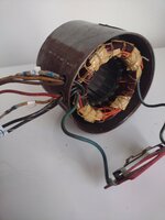
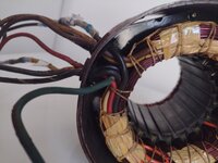
Hello everyone, long time follower first time thread poster. My name is Mike, I'm in my mid 30s with the amount of stuff of an 80 year old horder. I am currently working on a vintage Rockwell buffer, model 23-200 best I can tell. It is a single phase dual voltage motor with 7 leads. I got it with no switch or wiring hooked to anything. It doesn't smell burnt so hoping it works if I can figure out the wiring. From research I think it came with a dpst switch. I've attached pictures hoping it will help figure this out. Thank you.

You are using an out of date browser. It may not display this or other websites correctly.
You should upgrade or use an alternative browser.
You should upgrade or use an alternative browser.
7 lead marathon motor wiring help
- Thread starter Mikes8403
- Start date


alfredeneuman
Well-known member
The wiring diagrams for both voltages are on the motor's nameplate.
Cruzan80
Well-known member
I think he is having trouble, since the previous owner brought out three extra wires. Looking at the nameplate, doesn't seem like it was originally designed to swap direction. My guess is the four without homemade tags correspond to the wiring diagram.
2/4 is your start winding, not sure what the top of your pic means. 1/6 and 3/5 are your run windings. Not sure what you are saying 7 connects to.
2/4 is your start winding, not sure what the top of your pic means. 1/6 and 3/5 are your run windings. Not sure what you are saying 7 connects to.
alfadan
Well-known member
I think the other two wires go to a start capacitor which is missing along with the cover.
Sorry the first picture was showing what had continuity and to what resistance. I was thinking number 7 had to be something with a start compasitor since it would only have power until motor was up to speed. Where would the other wire for the start compasitor come from. The next thing that gets me confused is the diagram calls for yellow and black to one side of the switch but #5 and 3 are black. Numbers 2 and 6 are yellow, how do I know which to use? Thanks again for the help
Check post #3
With my limited knowledge on motors from hobby thangs. Here is my observation.
Not sure if that is pre-existing wiring numbering or this is your arbitrary numbers. Your numbering looks different***
Numbering wise usually 1-2,3-4 are run windings 5-6 are start winding. One end of start winding are connected the run winding dependent on the voltage configuration. So it would be 1 and 3 if low voltage, or just 1 if high voltage. So in my label convention for low voltage it would be 1,3,5. Etc
The other end of the of the start winding would go to a centrifugal switch usually they are named 7-8. If you have run cap it would also connect to run cap one end. So say if your centrifugal switch is 7-8 6,7 would be connected. 8 would go to one of the line or neutral, and not 1,3,5.
Run coils are usually equal in ohms, start coil are usually double the run coil.
How you connect the start coil and start cap combination*** determines the direction of rotation. How you connect the run coils determines the voltage level.
With my limited knowledge on motors from hobby thangs. Here is my observation.
Not sure if that is pre-existing wiring numbering or this is your arbitrary numbers. Your numbering looks different***
Numbering wise usually 1-2,3-4 are run windings 5-6 are start winding. One end of start winding are connected the run winding dependent on the voltage configuration. So it would be 1 and 3 if low voltage, or just 1 if high voltage. So in my label convention for low voltage it would be 1,3,5. Etc
The other end of the of the start winding would go to a centrifugal switch usually they are named 7-8. If you have run cap it would also connect to run cap one end. So say if your centrifugal switch is 7-8 6,7 would be connected. 8 would go to one of the line or neutral, and not 1,3,5.
Run coils are usually equal in ohms, start coil are usually double the run coil.
How you connect the start coil and start cap combination*** determines the direction of rotation. How you connect the run coils determines the voltage level.
Last edited:
Zeke
Well-known member
Be patient. @dogdog and a couple others helped me sort out a motor that I thought was wired 120v because the plug on the power cord was a 120v plug and where the motor was plugged in when I bought it was a typical 15A duplex. So I started with a big disadvantage and these guys got me going. I'm not sure, but @American Locomotive was another with lots of patience with me.
What I was trying to do was connect a drum switch with F and R. It was tough except for the help I got here.
What I was trying to do was connect a drum switch with F and R. It was tough except for the help I got here.
I used this post to help me on AC induction capacitor start motors. If yours is a capacitor start. or if it is a split phase capacitor run motor that have no centrifugal switch like the HF AC hoist motors...
start from post #17 and on have diagrams explaining how AC induction motor (cap start ones) works
start from post #17 and on have diagrams explaining how AC induction motor (cap start ones) works
Help Please ~ Wiring the Switch to the motor
Yes ... I know... there are many many posts to this question....but i find them all VERY confusing (Electrical work just escapes me) Here is my newer motor... and my switch... can someone please draw me a simple diagram with simple instructions on how to wire this dog up :~) Included are the...
www.practicalmachinist.com
alfredeneuman
Well-known member
The "CC" designation in the part number would lead me to believe it's designed for counterclockwise rotationLooking at the nameplate, doesn't seem like it was originally designed to swap direction.
alfadan
Well-known member
I do think the black and black/white wires go to a start capacitor, though the size of which (in uF) I don't know. black would go to one side of the capacitor, the black/white would go the other side. The other wires would simply be tied together or tied to line as per the diagram depending on what voltage you want.
Cruzan80
Well-known member
Looks like this was originally a buffer motor, hence why it only ran one way. Does 7 have continuity to anything? If not, there is your 6 wire configuration. If 7 does have continuity, is it when the cent switch is closed or open (thinking 7 may drop out the start winding).
Are any wires factory labeled, or are your numbers arbitrary? I still think the diagram is referring to the four without homemade labels (counting down from top, 2, 3, 4, and 6). For you, T1/T4 would be your brown and black, and T2/T3 would be yellow and red, respectively. Your wire labels of 2 and 4 would be T5/T8 (swap them to reverse direction). If 7 shows continuity, this allows an alternate path once the start circuit drops out, and would be tied to either T5 or T8 (IIRC).
What voltage do you want eventually? If 120V, easier as the start winding just attaches with everything else. 240 gets trickier, as the start winding only gets 120V across it.
Are any wires factory labeled, or are your numbers arbitrary? I still think the diagram is referring to the four without homemade labels (counting down from top, 2, 3, 4, and 6). For you, T1/T4 would be your brown and black, and T2/T3 would be yellow and red, respectively. Your wire labels of 2 and 4 would be T5/T8 (swap them to reverse direction). If 7 shows continuity, this allows an alternate path once the start circuit drops out, and would be tied to either T5 or T8 (IIRC).
What voltage do you want eventually? If 120V, easier as the start winding just attaches with everything else. 240 gets trickier, as the start winding only gets 120V across it.