To avoid these ads, REGISTER NOW!

707 Clone Rebuild

thatrevguy

Active member
Joined
Sep 19, 2021
Messages
25
Location
Chandler, AZ
Hello, I happened upon a horizontal 80 gallon air compressor that needs some love for $400.

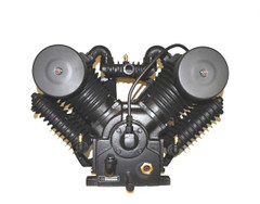
Pump looks like a Saylor Beall 707 clone. Body shop I bought it from said they bought the pump originally from NAPA 7 years ago.

Pretty obvious the pump fell on it's face at some point. Unloader valve on centrifugal unloader was missing and unloader pin slightly bent.

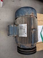
It came with a 10hp 3phase; swapping it for single phase 7.5hp for residential use.

2200.jpeg

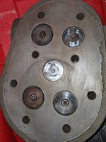
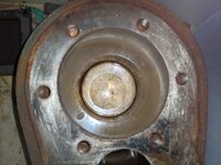
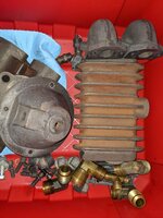
Got the pump completely disassembled. Bit of rust in valve assembly and lots of sludge. Bet they never changed the oil. Soaked everything in vinegar and simple green except rotating assembly. Cleaned up well by hand.

PXL_20210909_043550794.jpgPXL_20210909_043604031.jpgPXL_20210909_043636690.jpg

Got a tune up kit for the pump. Everything looks right except valve springs. The pump originally had 8 identical springs. Only 2 HP intake had different springs of lower stiffness... The TUK came with 12 springs total of two types. A set of 6 stiff springs and a set of 6 lower stiffness springs. Not sure how new springs should be assembled. Should I buy a different batch of springs? If I combine 2 lower stiffness springs together their combined resistance feels very close to a single stiffer spring. Having to combine springs seems odd.
 
To avoid these ads, REGISTER NOW!
OP
T

thatrevguy

Active member
Joined
Sep 19, 2021
Messages
25
Location
Chandler, AZ
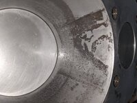
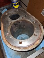
Cleaning cylinders, one of them looks much worse than I initially thought. Is boring it out while keeping same piston size even an option? PXL_20210925_031536857.jpg
 

gearhead1

Well-known member
Joined
Oct 14, 2013
Messages
1,935
Location
NC
Typically you would not bore it out and use the same size piston. Boring implies the imperfections are deep. Honing the cylinder might allow the same size piston to be used. It comes down to how deep the imperfections really are.
 

Speed-Racer

Well-known member
Joined
Aug 25, 2008
Messages
731
Once you clean up the cylinder with a hone, place a feeler gauge to see the clearance. Find a local machine shop, it’s only two cylinders. They can add a sleeve if necessary. The video shows you the process. Nice rebuild, we need more pics.
 
OP
T

thatrevguy

Active member
Joined
Sep 19, 2021
Messages
25
Location
Chandler, AZ
Once you clean up the cylinder with a hone, place a feeler gauge to see the clearance. Find a local machine shop, it’s only two cylinders. They can add a sleeve if necessary. The video shows you the process. Nice rebuild, we need more pics.
Thanks! This helps a lot. I don't feel any deep gouges. I'll take it over to a shop. Hopefully it only takes a couple thous to clear pitting. Sounds like from video clearance between piston and cylinder wall should not exceed 6 thous.

Few more pics
PXL_20210925_212312261.jpg
Old motor

PXL_20210925_212323333.jpg
New motor!

PXL_20210925_212540464.jpg
Reassembled head with rebuilt valves

PXL_20210925_212508428.jpgPXL_20210925_212502516.jpg
The good cylinders

PXL_20210925_212339065.jpgPXL_20210925_212433167.jpg
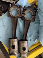
Pistons, one without rings I cleaned up. Came out of the rusty LP cylinder.
 

Attachments

  • PXL_20210925_212556210.jpg
    PXL_20210925_212556210.jpg
    403.7 KB · Views: 78
OP
T

thatrevguy

Active member
Joined
Sep 19, 2021
Messages
25
Location
Chandler, AZ
Alright, got a hold of mfg tech and learned a couple things:

1. In general, every inch of cylinder should allow at least 1/1000" of clearance.
2. Apparently pitting in the cylinder isn't a big deal as long as nothing is "sticking out" of the wall.

So I'm going to just hone it out some. Worst case scenario I order a new cylinder if things don't work out.
 

FMB4

Well-known member
Joined
Jan 19, 2017
Messages
2,926
Yep, just rent or buy a suitable brush hone. There are countless online videos on how to use these brush (some call them 'ball') hones.
 
OP
T

thatrevguy

Active member
Joined
Sep 19, 2021
Messages
25
Location
Chandler, AZ
Well I honed it out, the pitting is still there and it looks much worse than it feels. Fingernail doesn't catch on anything so I guess it's good enough.

At tdc it looks much better 😂

PXL_20210927_232927671.jpg
 
OP
T

thatrevguy

Active member
Joined
Sep 19, 2021
Messages
25
Location
Chandler, AZ
I would install the cleaned piston and using a set of feeler gauges. Check the clearance. The piston has to be very clean and you can purchase Lang feeler gauges inexpensively on Amazon or a tool truck. I think you are good as long as you cannot feel the pitting, this pump is only running at 800-900rpm??


Pitting can definitely still be felt. I think I'd need a different tool to remove material more aggressively... I honed the **** out of it.

Talking to the mfg tech he seemed unphased by my description of the cylinder's poor condition. His opinion was it should work "good enough" and if I was unhappy with the performance I'd be better off just replacing the cylinder.

My guess is I should expect some oil consumption, which... considering it will be operating in a domestic environment I can probably live with.

Pump RPM will be around 600RPM.

Ordered the gauges, appreciate the link!
 

The Tool Tyrant

ALLIANCE MEMBER
Joined
Dec 19, 2011
Messages
2,182
Location
Bonita, Ca. (San Diego)
I always run-in the rings without the head/s installed after a rebuild for approx. 15-30 minutes so I can see how well the rings are seating. You should see very little oil getting past the rings after 30 minutes of run-in.
Is your TUK kit a SB or specific for the clone?
 
OP
T

thatrevguy

Active member
Joined
Sep 19, 2021
Messages
25
Location
Chandler, AZ
I always run-in the rings without the head/s installed after a rebuild for approx. 15-30 minutes so I can see how well the rings are seating. You should see very little oil getting past the rings after 30 minutes of run-in.
Is your TUK kit a SB or specific for the clone?
TUK I picked up was for Coleman Powermate Sanborn SC46. I think NAPA references pump as C2.

I found a PDF manual for the pump but it's referenced as CI10SA, which ends up leading me to here:
 
OP
T

thatrevguy

Active member
Joined
Sep 19, 2021
Messages
25
Location
Chandler, AZ
As the valve springs are critical for pump performance, I personally would not use anything not specifically designed for that pump.
What's interesting is the manual has the above mentioned CI10SA reference, however, the parts diagram has a reference to SC46...

Attached PDF
 

Attachments

  • UM4-1070.pdf
    5.5 MB · Views: 6
OP
T

thatrevguy

Active member
Joined
Sep 19, 2021
Messages
25
Location
Chandler, AZ
Reviewing the parts breakdown, it appears you should have 3 types of springs, 4 of LP intake, 2 of HP intake and 4 of LP/HP exhaust, for a total of 10 springs.
Correct, the 4 LP Intake and 4 LP/HP exhaust springs were identical on disassembly of those valves. The 4 intake and 4 exhaust DO have different part numbers due to slightly different assemblies. Only the 2 HP Intake valves had unique springs from the rest.

The packaging I got in the TUK came with two bags. One had 7 springs and another had 5. 6 of the springs matched the original 8, other 6 matched the 2 HP intake springs. Which I found odd. My theory is there was maybe a mistake in packaging.
 
OP
T

thatrevguy

Active member
Joined
Sep 19, 2021
Messages
25
Location
Chandler, AZ
Little update!

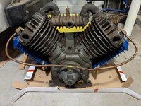
Got the pump reassembled. Not without trouble. Upon torqueing the aftercooler and intercooler bolts to spec ~14 ft-lbs; just about every single thread in heads disintegrated into a nice fine powder :). Picked up a helicoil kit from ace hardware and replaced all the threads in both heads. Torques down great now.
PXL_20211116_035843839.jpgPXL_20211119_061037195.jpg

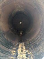
Pressure washed the 80 gal tank. A lot of black **** came out of it. No noticeable rust colored water. I might take another stab at washing it but not sure I can get it looking any better without soaking it in something. As long as I can get most of the debris out I think I'm good. Don't want it clogging up lines/valves.

PXL_20211119_061151456.jpgPXL_20211119_061208746.jpg
 
Last edited:

The Tool Tyrant

ALLIANCE MEMBER
Joined
Dec 19, 2011
Messages
2,182
Location
Bonita, Ca. (San Diego)
That pump has many different designations. U1258, SC46, EC10 and X-1220. I have no idea if they're all the same pump or not but it sure is confusing. I was told by Cary @ Pacific Air Compressor that the U1258, (sold through ACS) will accept Saylor-Beall valve components.
Your pump looks more like the pumps I mentioned above... https://www.ecompressedair.com/acs-replacement-ec10-bare-pump-(10-hp).aspx than the pump in the CA2 link you supplied. Look at the oil fil plug and centrifugal unloader and plumbing.
 
Last edited:
OP
T

thatrevguy

Active member
Joined
Sep 19, 2021
Messages
25
Location
Chandler, AZ
Would not be surprised if they are all the same. That EC10 you linked looks like an exact match.. Bought replacement intercoolers off SC46 model and they were a perfect fit.
 
To avoid these ads, REGISTER NOW!

The Tool Tyrant

ALLIANCE MEMBER
Joined
Dec 19, 2011
Messages
2,182
Location
Bonita, Ca. (San Diego)
FYI, I just installed a 10 HP WEG 1PH on a friends 'new to him' compressor and I found that the electrical access hole on the side of the capacitor case is NPT thread, not a straight thread.
 
Last edited:
OP
T

thatrevguy

Active member
Joined
Sep 19, 2021
Messages
25
Location
Chandler, AZ
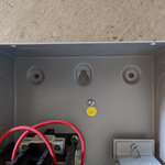
Got a small update. Motor and pump are attached. Getting belt tensioned was a PITA, 19" span needed .3" of give w/ about 9lbs of force. The single screw adjustment plate is a POS. Recommend getting double screw adjustment plate or you'll need to figure out a way to apply tension against the pulleys directly. Ended up reversing a clamp to do just that.

PXL_20220609_194247375.jpgPXL_20220609_194256432.jpgPXL_20220609_194310428.MP.jpg

Electrical parts coming in next week. If things go smoothly might have it turn over for first time :)
 

MacMcMacmac

Well-known member
Joined
Oct 21, 2014
Messages
1,593
Location
canada
Little update!

Got the pump reassembled. Not without trouble. Upon torqueing the aftercooler and intercooler bolts to spec ~14 ft-lbs; just about every single thread in heads disintegrated into a nice fine powder :). Picked up a helicoil kit from ace hardware and replaced all the threads in both heads. Torques down great now.

PXL_20211116_035843839.jpgPXL_20211119_061037195.jpg

Pressure washed the 80 gal tank. A lot of black **** came out of it. No noticeable rust colored water. I might take another stab at washing it but not sure I can get it looking any better without soaking it in something. As long as I can get most of the debris out I think I'm good. Don't want it clogging up lines/valves.

PXL_20211119_061151456.jpgPXL_20211119_061208746.jpg
Those disintegrating threads were also a massive issue with Kelloggs. After Kellogg went belly up in the early 2000s I noticed clones appearing pretty quickly afterwards. Turns out, they were being made by LaPlante Compressors in Hong Kong, the same company who makes these SB clones. LaPlante also stated on their website that they were the ones making the actual Kelloggs for CompAir even before they went defunct. I'm not sure what grade of cast iron they were using (floor sweepings?) but you needed a good set of HeliCoils on hand whenever you were working on a one.
 
OP
T

thatrevguy

Active member
Joined
Sep 19, 2021
Messages
25
Location
Chandler, AZ
Those disintegrating threads were also a massive issue with Kelloggs. After Kellogg went belly up in the early 2000s I noticed clones appearing pretty quickly afterwards. Turns out, they were being made by LaPlante Compressors in Hong Kong, the same company who makes these SB clones. LaPlante also stated on their website that they were the ones making the actual Kelloggs for CompAir even before they went defunct. I'm not sure what grade of cast iron they were using (floor sweepings?) but you needed a good set of HeliCoils on hand whenever you were working on a one.
I wouldn't be surprised if they were cast with floor sweepings. Will see how much mileage I get out of the pump.
 
OP
T

thatrevguy

Active member
Joined
Sep 19, 2021
Messages
25
Location
Chandler, AZ
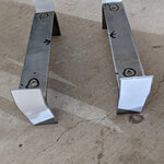
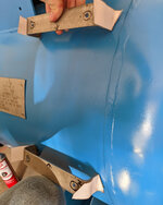
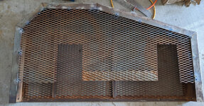
Got time to get some welding done. Welded on some brackets to mount the mag starter and re-attached back side of the belt guard (previous owner cut it off for reasons?). Got a little bit of welding left for intercooler brackets and electrical outlet box. Also JB welded in a replacement for the god awful drain plug the pump came with.


brackets.jpgcut-template.jpgmag-alignment.jpgtest-fit.jpgtank-prep.jpgtank-weld.jpgmag-starter-attached.jpgbelt-guard-repair.jpgdrain-plug.jpg
 

American Locomotive

Well-known member
Joined
Jan 8, 2017
Messages
11,014
Location
Rhode Island
Welding on a pressure vessel like that is generally considered a pretty bad move. There were already pre-drilled holes on the welded on plate to attach brackets to hold things like a mag starter.
 
OP
T

thatrevguy

Active member
Joined
Sep 19, 2021
Messages
25
Location
Chandler, AZ
I'll be pressure testing it. Tank walls are 1/4" thick and brackets are 1/8". Used .030 flux core with 250 WFS @ 18.9 Volts. I'd be surprised if structural integrity is compromised by the welds; especially with the 1/4" steel acting as a giant heatsink.
 

American Locomotive

Well-known member
Joined
Jan 8, 2017
Messages
11,014
Location
Rhode Island
The tank walls are not anywhere near 1/4" thick. The data plate actually tells you. Head: 0.149", Shell: 0.181. Regardless of wall thickness, it's still very bad practice to weld on a certified pressure vessel - especially one of that size. If that tank ruptured at 175 PSI, it would pretty much demolish most of your garage.

Fill it to the top with water, then apply pressure. I'd want at least 225-250 PSI in there before I felt comfortable using it. In all odds, it will *probably* be fine, but in the future, please do not weld directly on an air tank. Just bolt things into the existing weldments. There have been a number of tank explosions posted on here, and one thing they all had in common was that they were welded on.
 
Last edited:

will335i

Well-known member
Joined
Feb 18, 2020
Messages
497
Location
IL
I'll be pressure testing it. Tank walls are 1/4" thick and brackets are 1/8". Used .030 flux core with 250 WFS @ 18.9 Volts. I'd be surprised if structural integrity is compromised by the welds; especially with the 1/4" steel acting as a giant heatsink.
You will be really surprised when it goes boom. I am not trying to be a ****, I have a degree and mechanical engineering and one of my previous roles was ensuring proper testing and certification of pressure vessels and pressure boundaries. I had to have a contractor retest a whole process line because they welded some dead-legs onto the pipe after they did the hydro-test. You put heat on pressure boundary so it is no longer rated the end. I would recommend having someone certified doing the test. I can offer some guidance on how to perform the test but take no responsibility should something go wrong.
 
OP
T

thatrevguy

Active member
Joined
Sep 19, 2021
Messages
25
Location
Chandler, AZ
You will be really surprised when it goes boom. I am not trying to be a ****, I have a degree and mechanical engineering and one of my previous roles was ensuring proper testing and certification of pressure vessels and pressure boundaries. I had to have a contractor retest a whole process line because they welded some dead-legs onto the pipe after they did the hydro-test. You put heat on pressure boundary so it is no longer rated the end. I would recommend having someone certified doing the test. I can offer some guidance on how to perform the test but take no responsibility should something go wrong.
Thanks for the input. From what I have gathered looks like I need to fill the tank up with water then pressurize it up to 150% of operating pressure (think my pressure washer can manage) then let it sit for 30 minutes.
 

will335i

Well-known member
Joined
Feb 18, 2020
Messages
497
Location
IL
Some highlights from our Hydrostatic test procedure:

- Test gauge ranges shall be selected so that the test pressure of the system falls between 40% and 80% of the gauge scale range.
- An ASME Code approved pressure relief device shall be installed in the test loop during the test. The relief valve shall be installed in a manner that does not allow it to be isolated from the test loop during the test. The device shall be set and calibrated to relieve at the greater of 25 psig or 10% above the test pressure. This pressure relief device is in addition to any pressure relief devices supplied at the pressure source.
- A preliminary check shall be made by pressurizing the test loop to not more than 25 psig and verifying pressure holds for a minimum of two (2) minutes before proceeding. The pressure shall be increased gradually in steps of 50 psig. At each increment of 50 psig, the pressure shall be held steady for one (1) minute before proceeding to a higher pressure.
- The test pressure is to be measured at the high point of the system, or, if measured below the high point of the system, the required pressure reading shall be adjusted upward to reflect the additional liquid head between the high point and the measured point.
- Hold the test pressure for a period of time sufficient to permit a thorough inspection of all joints for leakage, but in no case, less than 10 minutes.
 
OP
T

thatrevguy

Active member
Joined
Sep 19, 2021
Messages
25
Location
Chandler, AZ
Some highlights from our Hydrostatic test procedure:

- Test gauge ranges shall be selected so that the test pressure of the system falls between 40% and 80% of the gauge scale range.
- An ASME Code approved pressure relief device shall be installed in the test loop during the test. The relief valve shall be installed in a manner that does not allow it to be isolated from the test loop during the test. The device shall be set and calibrated to relieve at the greater of 25 psig or 10% above the test pressure. This pressure relief device is in addition to any pressure relief devices supplied at the pressure source.
- A preliminary check shall be made by pressurizing the test loop to not more than 25 psig and verifying pressure holds for a minimum of two (2) minutes before proceeding. The pressure shall be increased gradually in steps of 50 psig. At each increment of 50 psig, the pressure shall be held steady for one (1) minute before proceeding to a higher pressure.
- The test pressure is to be measured at the high point of the system, or, if measured below the high point of the system, the required pressure reading shall be adjusted upward to reflect the additional liquid head between the high point and the measured point.
- Hold the test pressure for a period of time sufficient to permit a thorough inspection of all joints for leakage, but in no case, less than 10 minutes.
Thank you, this is super helpful. One question, would you recommend testing at 150% of target operating pressure (175 PSI) or the tank's MAWP (200 PSI)?
 
OP
T

thatrevguy

Active member
Joined
Sep 19, 2021
Messages
25
Location
Chandler, AZ
Did hydrostatic test tonight. Got pressure up to 300 psi and did joint inspection. Didn't find any leaks. Let it sit another 30 minutes and noticed a slight pressure drop. Did another inspection but found no wet spots. Below is picture of gauge at start and end of the 30 minute interval:

Start
300-start.jpeg

End
300-end.jpeg
 
To avoid these ads, REGISTER NOW!
Top Bottom