To avoid these ads, REGISTER NOW!

74TX650 build.

toglhot

Well-known member
Joined
Nov 20, 2021
Messages
153
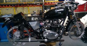
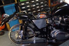
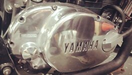
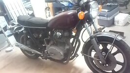
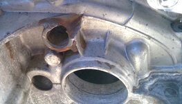
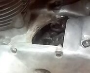
I bought this bike a few years ago with the intention of rebuilding it into a cafe raceresque custom. I started with a rusted out hulk: The crankcase was torn apart by an errant chain, cam chain guides were worn through, cam chain was so stretched the PO had elongated the holes on the points backing plate to time it. Compression was down to around 90/80 psi, valves badly pitted, oil was like treacle, carbs were gunked up, exhaust was rusted out, all steel fasteners were completely rusted, spokes were rusted and the aluminium was badly pitted and oxidised.

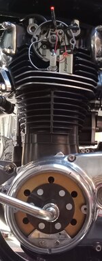
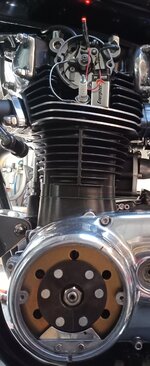
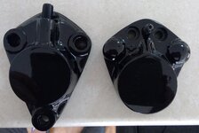
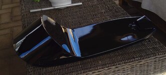
This was going to be a long project, I can't ride bikes anymore due to advanced rheumatoid arthritis and have a lot of trouble using tools, complements of fused fingers, so I'm in no hurry. The bike is almost finished now, just need to paintt the seatpan and cover it, fit tyres and fit caliper pistons when they arrive. Realistically, it'll never be finished, I'm always finding new things to make for it. So far I've rebuilt the engine with new crankcases, rebore, new pistons, rings gudgeons, cam chain, guides, valve regrind, a few gearbox parts, seals, gaskets, stainless Allen's, painted and cooked black.

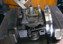
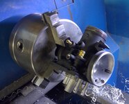
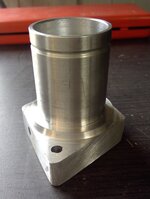
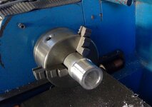
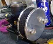
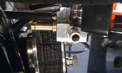
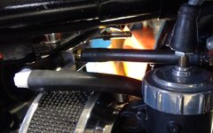
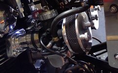
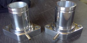
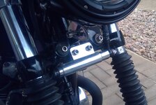
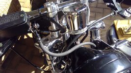
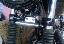
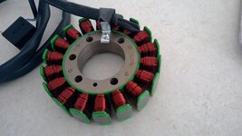
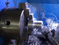
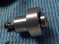
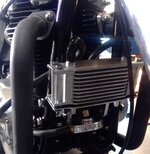
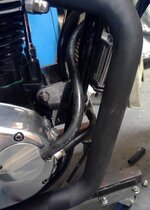
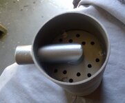
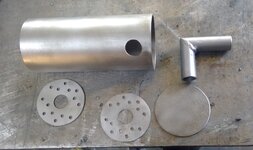
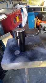
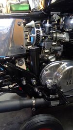
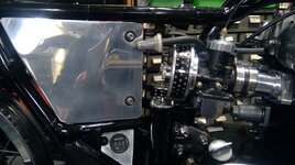
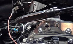
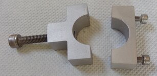
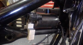
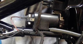
Mods include: PMA conversion, VM carb conversion, spin on filter conversion, oil cooler, single points conversion, dual output coil, twin wiring harnesses, exhaust pipes and mufflers, all parts for these mods made in my workshop, PMA mount, extended manifolds, single points cam and backing plate, exhaust pipes, mufflers and mounts.

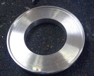
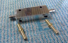
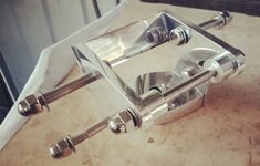
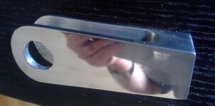
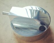
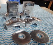
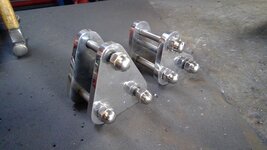
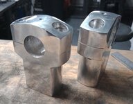
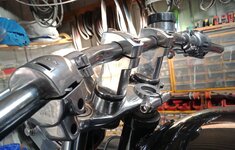
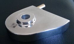
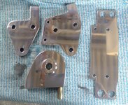
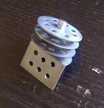
Some other bits and pieces I've machined or fabricated: Tail light, headlight bracket, engine mounts, side panels, battery cover, fuel distributor, air cleaners, brake hose block, risers, chain adjusters, brake anchor, brake rod and clevis, etc.

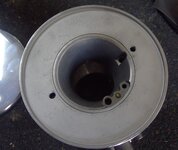
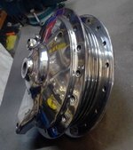
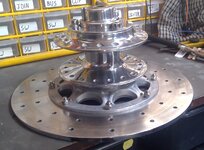
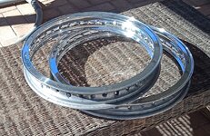
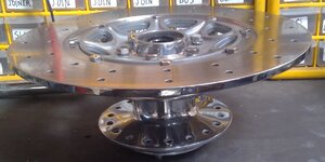
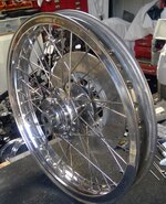
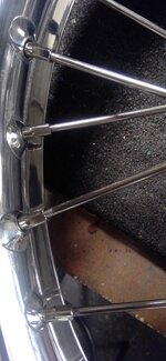
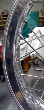
I've rebuilt the wheels using stainless spokes, the hubs were skimmed on the lathe.

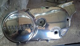
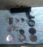
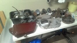
The bike came with a heap of extra parts, most of it ****: Spoked wheels, speedos, tachos, speedo drive, carbs, side covers, and so on.

The pics show the bike as bought and where I'm up to with it. Pics and text on mods to come.

machined in my shop, along with air filters, PMA mount, single point conversion, cam and backing plate machined in my shop. Also machined or fabricated in my shop, aluminium side covers, battery carrier, reg/rect mount, tail light, engine mounts,
 

Attachments

  • as bought right.jpg
    as bought right.jpg
    88.1 KB · Views: 84
  • spokewheels.jpg
    spokewheels.jpg
    56.8 KB · Views: 65
  • extraparts.jpg
    extraparts.jpg
    293.8 KB · Views: 46
  • spoke.jpg
    spoke.jpg
    600.1 KB · Views: 42
  • shocks.jpg
    shocks.jpg
    411.6 KB · Views: 42
  • oxidismed right cover.jpg
    oxidismed right cover.jpg
    425.4 KB · Views: 38
  • damaged shifter drum mount.jpg
    damaged shifter drum mount.jpg
    518.7 KB · Views: 39
  • damaged crankcase.jpg
    damaged crankcase.jpg
    38.8 KB · Views: 60
Last edited:
To avoid these ads, REGISTER NOW!
OP
T

toglhot

Well-known member
Joined
Nov 20, 2021
Messages
153
Current status.
 

Attachments

  • WIN_20220412_15_43_49_Pro (1).jpg
    WIN_20220412_15_43_49_Pro (1).jpg
    246.2 KB · Views: 66
  • WIN_20220412_15_44_21_Pro.jpg
    WIN_20220412_15_44_21_Pro.jpg
    224.5 KB · Views: 69

555

Well-known member
Joined
Nov 10, 2007
Messages
2,286
Location
Nomad-Arkansas & Georgia
I have a 74 TX650. It is family owned since new. My brother in law purchased it when he worked for the local Yamaha dealer. He added Shelby Dowd wheels and a rear disk brake. I've been the caretaker it for about 20 years and it is kept in a spare bedroom at our Arkansas farm. You've done a nice job bringing your bike back to life. In 1991, I was given two Yamaha 650s that had belonged to a 1% club member. The club required American made and he had not ridden either bike since the early 80s. One was a 1970 XS650 and the other was a 79 Special. The 1970 had no frame numbers or title and was a rat bike. I turned it into a desert sled similar to the old California Triumph 650s. The Special was in very nice condition and all it needed was a good carb cleaning. I sold both of them when we moved from Virginia to Texas in 1994.
 
OP
T

toglhot

Well-known member
Joined
Nov 20, 2021
Messages
153
I originally had BS38s on the bike, but discarded then in favour of VM 34 carbs. The carb came with manifolds and rubber boots, but when fitted the throttle cable interfered with the petcocks, so, I machined up two extended manifolds so the carbs cleared the petcocks. These were made up of two pieces I machined on the lathe and then pressed together. I also found it necessary to swap the petcocks right to left, left to right to get the clearance needed.

I originall had pods on the carbs, but found the inner diameter of the pods was appreciably smaller than the bellmouth inlet, so, discarded them and built two pancake style filters. The inner plate was turned up on the lathe from a block of 4" aluminium with two holes drilled and tapped into the collar for fixing the outer plate. The carb was mounted on the lathe and the outer surface of the bellmouth cleaned up and the filter plate pressed over the bellmouth.
 

Attachments

  • 18.jpg
    18.jpg
    797.7 KB · Views: 56
  • 17.jpg
    17.jpg
    717.3 KB · Views: 37
  • 23.jpg
    23.jpg
    351.2 KB · Views: 35
  • 25.jpg
    25.jpg
    415.1 KB · Views: 34
  • 14.jpg
    14.jpg
    533.9 KB · Views: 31
  • 0.jpg
    0.jpg
    65.3 KB · Views: 29
  • WIN_20211219_15_47_40_Pro.jpg
    WIN_20211219_15_47_40_Pro.jpg
    712.3 KB · Views: 28
  • c.jpg
    c.jpg
    858.4 KB · Views: 28
  • 1 (2).jpg
    1 (2).jpg
    504.3 KB · Views: 26
  • WIN_20220122_16_36_42_Pro.jpg
    WIN_20220122_16_36_42_Pro.jpg
    453.2 KB · Views: 25
Last edited:
OP
T

toglhot

Well-known member
Joined
Nov 20, 2021
Messages
153
The outer filter plate was beaten up from 1.7mm aluminium, two mounting holes drilled and the plate polished. To fix the two plates together, long threaded studs were screwed into the inner plate collar, the outer plate fitted and tow knurled, threaded nuts I turned up on the lathe and fitted. The filter material cover is some sort of woven, stainless wire which I'm not happy with, that will be replaced with perforated sheet metal when I can find a supplier.

I did have a bunch of rubber tubes and adpter under the tank, linking the two sides of the tank and inking carbs with petcocks, but that was awfully untidy, so, I machined up a fuel distributor block. The block is mounted under the front lip of the aluminium battery carrier I welded together some time ago. A block of aluminium was mounted in the lathe and an 8mm barb, turned either end, then a 5.5mm through hole was drilled linking both barbs. Two 6mm barbs were then turned up from brass, pressed into the front of the block and drilled through to the 5.5mm through hole.

The two 6mm brass barbs are inked to the petcock by a short length of fuel hose interupted by a small inline filters, the two outer 8mm barbs are linked to the carbs via short lengths of 8mm fuel hose. The fuel distributor block aside from neatening things up has the added advantage of leveling the fuel level in the tank when the level gets below the tank tunnel, thus stopping one carb from starving.
 

Attachments

  • 26.jpg
    26.jpg
    377.7 KB · Views: 22
  • 11.jpg
    11.jpg
    375.4 KB · Views: 21
  • 10.jpg
    10.jpg
    339.9 KB · Views: 21
  • 6.jpg
    6.jpg
    500.2 KB · Views: 22
  • 321458149_525805192943390_7736369311548104776_n.jpg
    321458149_525805192943390_7736369311548104776_n.jpg
    799.9 KB · Views: 21
  • 321547138_1498189487327707_8219572784725550045_n.jpg
    321547138_1498189487327707_8219572784725550045_n.jpg
    886.2 KB · Views: 21
  • 321423419_689718422821105_1369725655134132331_n.jpg
    321423419_689718422821105_1369725655134132331_n.jpg
    410.6 KB · Views: 20
  • 321462785_1282534605930134_7720880614290658264_n.jpg
    321462785_1282534605930134_7720880614290658264_n.jpg
    336.4 KB · Views: 20
  • WIN_20230109_16_30_06_Pro.jpg
    WIN_20230109_16_30_06_Pro.jpg
    249 KB · Views: 17
  • WIN_20230109_16_29_54_Pro.jpg
    WIN_20230109_16_29_54_Pro.jpg
    254.3 KB · Views: 24
OP
T

toglhot

Well-known member
Joined
Nov 20, 2021
Messages
153
The finished product.
 

Attachments

  • 27.jpg
    27.jpg
    357.5 KB · Views: 28
  • 29 (1).jpg
    29 (1).jpg
    357.9 KB · Views: 27
  • 28.jpg
    28.jpg
    485.1 KB · Views: 23
  • 31.jpg
    31.jpg
    613.7 KB · Views: 23
  • 32.jpg
    32.jpg
    559.8 KB · Views: 29
OP
T

toglhot

Well-known member
Joined
Nov 20, 2021
Messages
153
Lots of polished aluminium on this build, here's some some stuff I polished.
 

Attachments

  • engine mounts oil filter housing complete.jpg
    engine mounts oil filter housing complete.jpg
    176.5 KB · Views: 24
  • f.jpg
    f.jpg
    613.6 KB · Views: 24
  • left engine cover.jpg
    left engine cover.jpg
    385 KB · Views: 24
  • rear hub1.jpg
    rear hub1.jpg
    73.5 KB · Views: 23
  • fronthuband disk.jpg
    fronthuband disk.jpg
    227 KB · Views: 23
  • 3.jpg
    3.jpg
    45.1 KB · Views: 22
  • bracket left fitted.jpg
    bracket left fitted.jpg
    586.8 KB · Views: 19
  • ally side.jpg
    ally side.jpg
    669.2 KB · Views: 18
  • oil inlet cover outer.jpg
    oil inlet cover outer.jpg
    222.1 KB · Views: 18
  • WIN_20220830_15_55_27_Pro (1).jpg
    WIN_20220830_15_55_27_Pro (1).jpg
    559.1 KB · Views: 17
Last edited:
OP
T

toglhot

Well-known member
Joined
Nov 20, 2021
Messages
153
Continued.
 

Attachments

  • rear hub1.jpg
    rear hub1.jpg
    73.5 KB · Views: 17
  • risers disassembled 2.jpg
    risers disassembled 2.jpg
    448.1 KB · Views: 16
  • topmount5.jpg
    topmount5.jpg
    690.7 KB · Views: 16
  • WIN_20220823_14_37_09_Pro.jpg
    WIN_20220823_14_37_09_Pro.jpg
    537.1 KB · Views: 17
  • WIN_20220823_15_03_09_Pro.jpg
    WIN_20220823_15_03_09_Pro.jpg
    631.2 KB · Views: 18
  • WIN_20220830_15_57_46_Pro.jpg
    WIN_20220830_15_57_46_Pro.jpg
    699.6 KB · Views: 17
  • 2 polished rims.jpg
    2 polished rims.jpg
    308.9 KB · Views: 15
  • 310290408_3390827947843894_3792670857924279849_n.jpg
    310290408_3390827947843894_3792670857924279849_n.jpg
    339.6 KB · Views: 15
  • rear engmts and bolts.jpg
    rear engmts and bolts.jpg
    33.6 KB · Views: 16
  • 233063901_3065483153711710_7168761392392930978_n.jpg
    233063901_3065483153711710_7168761392392930978_n.jpg
    176.4 KB · Views: 21
OP
T

toglhot

Well-known member
Joined
Nov 20, 2021
Messages
153
Like everything else on the bike, the front brake parts had seen better days, the master cylinder was badly corroded the front brake hoses were rotted and full,of gunk, as was the caliper. I decided on an after market master cylinder and bought two new hoses off eBay with the appropriate ratings.

I could have used a single hose, but wanted to retain the stock hydraulic brake switch and the aluminium hose joining block bolted to the lower triple tree. Unfortunately, the banjos on each end of the lower hose were on the same plain, requiring the lower hose to be twisted through 90 degrees to fit.

Not a good idea, so, I machined up a new block with banjo fitting points at the correct angle. Mostly machined up on the mill, the ends were spun on the lathe and the rounded front shaped on the linisher. The lower hose and brake switch attach to the back of the block, whilst the upper hose is attached to the left side of the block.

The block is reasonably long, so a through hole had to be drilled from both ends to reach the lower hose attachment point and the open end blocked with a stainless screw and copper washer.
 

Attachments

  • 310290408_3390827947843894_3792670857924279849_n.jpg
    310290408_3390827947843894_3792670857924279849_n.jpg
    339.6 KB · Views: 19
  • 307678224_3390828151177207_4124538913492109092_n.jpg
    307678224_3390828151177207_4124538913492109092_n.jpg
    545.7 KB · Views: 18
  • 310310999_3390828724510483_4939313714668790861_n.jpg
    310310999_3390828724510483_4939313714668790861_n.jpg
    675.7 KB · Views: 16
  • 311646673_3390828714510484_4892292495566418025_n.jpg
    311646673_3390828714510484_4892292495566418025_n.jpg
    533.1 KB · Views: 14
  • 310502716_3390828187843870_7282701913890634183_n.jpg
    310502716_3390828187843870_7282701913890634183_n.jpg
    310.1 KB · Views: 15
  • 310485007_3390828084510547_1536601018598377535_n.jpg
    310485007_3390828084510547_1536601018598377535_n.jpg
    747.8 KB · Views: 18
OP
T

toglhot

Well-known member
Joined
Nov 20, 2021
Messages
153
The TX 650 has a brushed electro magnet alternator, the output rising with the revs, zip at idle. I decided to do a permanent magnet alternator conversion, but the kits are expensive at around $450 Aust, so, I did a conversion myself sourcing a Banshee rotor and an XV stator and regulator/rectifier on ebay for around $130.

Its critical the stator sits central with the rotor's magnetic field, so, I set the stator inside the rotor, mounted the rotor on the crankshaft and took some measurements. With the measurements in hand. I spun up a mount on the lathe. I didn't have any aluminium thick enough so made the mount in two pieces.

Unfortunately, there were no timing marks on the Banshee rotor. To fix, I timed the engine with the stock alternator, removed it, then mounted the PMA, made up a timing plate, mounted it in the left side cover and scribed some lines on the rotor and timing plate.

The Banshee rotor has a 6mm keyway, whereas the TX crankshaft has a 5mm woodruff keyway, so I turned up a piece of stock to the right diameter for the keyway, cut it in half, stepped it, then shaved it to the right height.

Finally I made a plate to carry the regulator/rectifier and mounted it behind the battery carrier.
 

Attachments

  • rotor 2.jpg
    rotor 2.jpg
    209.1 KB · Views: 16
  • stator.jpg
    stator.jpg
    219.3 KB · Views: 15
  • 118767751_3567911763254266_5112981845750737633_n.jpg
    118767751_3567911763254266_5112981845750737633_n.jpg
    200.5 KB · Views: 15
  • 118768290_2796583297268365_6752452443242133433_n.jpg
    118768290_2796583297268365_6752452443242133433_n.jpg
    145.2 KB · Views: 16
  • 118869712_3567911396587636_6656403571706206189_n.jpg
    118869712_3567911396587636_6656403571706206189_n.jpg
    202.3 KB · Views: 15
  • 118767888_2796584063934955_6356803461352077540_n.jpg
    118767888_2796584063934955_6356803461352077540_n.jpg
    409.4 KB · Views: 15
  • timing pointer1.jpg
    timing pointer1.jpg
    279 KB · Views: 15
  • timming pointer from inside cover.jpg
    timming pointer from inside cover.jpg
    485.2 KB · Views: 14
  • timing pointer and cover installed.jpg
    timing pointer and cover installed.jpg
    483.8 KB · Views: 14
  • woodruff3.jpg
    woodruff3.jpg
    404.6 KB · Views: 18
OP
T

toglhot

Well-known member
Joined
Nov 20, 2021
Messages
153
Single points conversion.

The TX650 has dual points, similar to the old Brit twins, a little time consuming to get them right, so, I decided to improve the setup by converting to a single points setup to simplify timing. I could have gone the electronic ignition route like everyone else, but I like all things mechanical so decided to stick with points.

There was a dual lobe cam available for a while, but apparently it wasn't to accurate so was withdrawn from the market, I then decided to make my own. First up I made a single points backing plate, that done, next came the dual lobe points cam: I first machined two lobes on an 18 mm piece of stock, then mounted it on the mill and cut the keyway, no luck, the timing was way out. I tried doing it this way a few times, but didn't achieve the results I was after, so, I did it in reverse: Cut the keyway on the 18mm piece of stock then mounted it on the advance rod, timed the engine, set the points plate in the middle position and marked where the heel of the points sat.

To time the points I made up a couple of LED timing lights, one working off a 9v battery through a resistor, the other working off a button battery

I then mounted the cam in the vice and used a file to to shape the lobe, using the LED light to get the opening/closing point in the right position. After a few files I managed to get it spot on, so, I then turned the engine over 180 degrees and marked where the points heel sat on the opposite side of the cam for the second cylinder, filed it a few times and again got it spot on. Next was the dwell, again, I used the LED light to get the dwell right.

Once it was finished I fired the bike up and it ran beautifully. The cam is only made from mild steel, so might not wear too well, that being the case, I'll make another from bronze.
 

Attachments

  • timed right.jpg
    timed right.jpg
    348.8 KB · Views: 14
  • led 2.jpg
    led 2.jpg
    450.6 KB · Views: 14
  • 3 timing lights.jpg
    3 timing lights.jpg
    409 KB · Views: 15
  • single points cam.jpg
    single points cam.jpg
    327.9 KB · Views: 16
  • polished points cam2.jpg
    polished points cam2.jpg
    290.5 KB · Views: 16
  • points plate assempled.jpg
    points plate assempled.jpg
    899.6 KB · Views: 15
  • 2points.jpg
    2points.jpg
    315.2 KB · Views: 15
  • timed left.jpg
    timed left.jpg
    373.5 KB · Views: 15
  • coil bracket.jpg
    coil bracket.jpg
    765.2 KB · Views: 16
  • coil bracket and coil and engine mount fitted right side.jpg
    coil bracket and coil and engine mount fitted right side.jpg
    848.9 KB · Views: 24
Last edited:
OP
T

toglhot

Well-known member
Joined
Nov 20, 2021
Messages
153
I decided on flat, drag bars on risers for the bike, so bought a set of drag bars and looked around for some risers. Couldn't find any I liked, so I made my own. I started off with two slabs of 25mm aluminium, chucked them in the four jaw and turned them to the shape I wanted, then turned them around and drilled and tapped for 10mm mounting bolts. I then drilled a 7/8" hole for the bars, drilled and tapped 8mm holes either side for clamping bolts, then mounted them on a vertical slide on the lathe, mounted a .8mm slit saw in the chuck and cut through to remove the caps. Last couple of jobs were to counter bore the caps a little for stainless Allen head clamping bolts and spin up four 3mm thick aluminium mounting washers.
 

Attachments

  • risers assembled.jpg
    risers assembled.jpg
    214.6 KB · Views: 17
  • 7 (1).jpg
    7 (1).jpg
    284.9 KB · Views: 18
  • risers front right.jpg
    risers front right.jpg
    347.3 KB · Views: 18
  • risers rear left.jpg
    risers rear left.jpg
    258.7 KB · Views: 18
  • risers rear right.jpg
    risers rear right.jpg
    166.2 KB · Views: 21
OP
T

toglhot

Well-known member
Joined
Nov 20, 2021
Messages
153
Slaved away today - making a clutch slave cylinder. I made it so it sits in the left cover, protruding through the clutch screw actuatorr hole. I managed to get the tolerances better than the caliper tolerances: The bore is dead on 25mm, the piston dead on 24.97, a really nice fit.

I couldn't find any seals similar to the caliper seals, but found a hydraulic pressure seal and dust seal, but I have to find a 25 mm internal circlip before cutting the circlip groove. I also,have to drill a couple of holes in the collar to suit the holes in the side cover, then bore out the hole in the cover to 30mm and drill out the M5 securing threads. Once done two M5 Allen's will bolt through the outside of the cover, holding the slave cylinder in place.

I did make one mistake, got carried away on the lathe and cut the collar down to 18mm, that only leaves a 6 mm threaded hole in the collar of the slave cylinder. Hopefully this may work as the screws are really on locating pegs.

Before modifying the side cover I'll order a hydraulic hose. Not sure what size master cylinder to get, but I'll try the slave out on the 17mm braker master cylinder first, that should give a clue, unless of course, someone here knows what size master to go with the 25mm slave for a nice light clutch pull: Fused fingers so grip isn't the best.

I'm hoping to find a pair of matching radial clutch/brake master cylinders.
 

Attachments

  • WIN_20230117_15_32_06_Pro.jpg
    WIN_20230117_15_32_06_Pro.jpg
    628.1 KB · Views: 15
  • WIN_20230117_15_33_13_Pro.jpg
    WIN_20230117_15_33_13_Pro.jpg
    634 KB · Views: 14
  • WIN_20230117_15_35_19_Pro.jpg
    WIN_20230117_15_35_19_Pro.jpg
    751.5 KB · Views: 13
  • WIN_20230117_15_36_37_Pro.jpg
    WIN_20230117_15_36_37_Pro.jpg
    856.7 KB · Views: 13
  • WIN_20230117_15_45_26_Pro.jpg
    WIN_20230117_15_45_26_Pro.jpg
    504.6 KB · Views: 13
  • WIN_20230117_15_51_35_Pro.jpg
    WIN_20230117_15_51_35_Pro.jpg
    377.6 KB · Views: 13
  • WIN_20230117_15_55_26_Pro.jpg
    WIN_20230117_15_55_26_Pro.jpg
    466.3 KB · Views: 12
  • WIN_20230117_15_55_52_Pro.jpg
    WIN_20230117_15_55_52_Pro.jpg
    412.4 KB · Views: 12
  • WIN_20230117_15_57_22_Pro.jpg
    WIN_20230117_15_57_22_Pro.jpg
    701.3 KB · Views: 12
  • WIN_20230117_15_58_22_Pro.jpg
    WIN_20230117_15_58_22_Pro.jpg
    877.1 KB · Views: 16
OP
T

toglhot

Well-known member
Joined
Nov 20, 2021
Messages
153
I may not get to use the slave. After looking around for master cylinders, I couldn't find matching clutch/brake masters of the size I'll need (12/17mm), so it'll be either non matching masters, or, an easy pull for the stock cable!
 
OP
T

toglhot

Well-known member
Joined
Nov 20, 2021
Messages
153
I decided on spoked wheels for the bike as they look a lot better than alloys, when shined up. The bike came with alloys fitted and a couple of original spoked wheels for that model as spares. They were in pretty sorry shape, rims were badly oxidised, pitted and had quite a bit of damage inflicted on it by the PO. He must have used hammers, chisels, screwdriver, pry bars, what ever he could lay his hands on to remove and refit tyres, going on the damage.

The spokes were totally rusted out, so they went in the bin and I ordered ome stainless spokes from a local supplier, he only had spokes for the front, so I ordered them and wa prepared to wait until he got some rear spokes in.

While I was waiting for the spoke, I ground the edge of the rims down with a 240 grit disk on an angle grinder and the damage to the flat area was ground with a nylon fibre wheel, then the rims polished. I managed to remove most of the damage, but there are some deep gouges just too deep to remove, so they'll have to remain.

I mounted the rear hub on the lathe and skimmed the flanges true, then removed the casting bridges between fins, trued the fins, then polished. The front hub was also mounted on the lathe, flanges skimmed, trued, and the deep bridge between flanges reduced a little so I could get in with a mop to polish.

The front spokes arrived so I laced the front wheel, centred, trued and torqued the spokes only to find 3 mm of thread showing before the ******. I removed a couple of spokes and compared ithe stock spokes and sure enough, the spokes had been threaded incorrectly, the thread being 3mm too long. I lodged a complaint with the supplier, but all I got in return was a series of abusive texts and emails and he disabled my account.

So, I next ordered some stainless rear spokes from Heidens in the Netherlands, They arrived and I laced the rear wheel, trued, centred and torqued the ******* - perfect, no thread showing.

The wheels make the bike, but I do cringe when I look at the exposed thread on the front wheel.
 

Attachments

  • WIN_20211031_18_18_14_Pro.jpg
    WIN_20211031_18_18_14_Pro.jpg
    494.5 KB · Views: 12
  • dirtyrim.jpg
    dirtyrim.jpg
    230.9 KB · Views: 13
  • 2 polished rims.jpg
    2 polished rims.jpg
    308.9 KB · Views: 13
  • rear hub1.jpg
    rear hub1.jpg
    73.5 KB · Views: 13
  • rearhub1.jpg
    rearhub1.jpg
    354.8 KB · Views: 13
  • fronthuband disk.jpg
    fronthuband disk.jpg
    227 KB · Views: 14
  • fronthub7.jpg
    fronthub7.jpg
    270.9 KB · Views: 14
  • front 1.jpg
    front 1.jpg
    721 KB · Views: 14
  • front 2.jpg
    front 2.jpg
    557.3 KB · Views: 15
  • front spoke close up.jpg
    front spoke close up.jpg
    354.1 KB · Views: 14
OP
T

toglhot

Well-known member
Joined
Nov 20, 2021
Messages
153
Continued. While I wa at it, I renewed the stock spacers with stainless ones. Dust covers were turned up from aluminium and pressed onto the spacers.
 

Attachments

  • spacers.jpg
    spacers.jpg
    543 KB · Views: 12
  • spacer4.jpg
    spacer4.jpg
    797.9 KB · Views: 10
  • spacer.jpg
    spacer.jpg
    373.4 KB · Views: 8
  • spacer2.jpg
    spacer2.jpg
    367 KB · Views: 10
  • rear side spoke  close up.jpg
    rear side spoke close up.jpg
    450.4 KB · Views: 10
  • rear sprocket side 2.jpg
    rear sprocket side 2.jpg
    692.1 KB · Views: 10
  • rear brake side 2.jpg
    rear brake side 2.jpg
    796.8 KB · Views: 18
  • right rear.jpg
    right rear.jpg
    785 KB · Views: 19
To avoid these ads, REGISTER NOW!
OP
T

toglhot

Well-known member
Joined
Nov 20, 2021
Messages
153
Now the bike is almost finished, just needs the seat covered and tyres, so I put on my glasses and cast a critical eye over it. Story of my life – never, ever happy, and what do you know, I found a few things I’m not happy with, so, I can start making parts for it again, whoo hoo!. First up was a new spin on filter/cooler. The current one totally underwhelms me: hoses look untidy, the spin on filter mount looks too blocky, so, that went in the bin. One of the screws holding the mount to the engine bracket was a bit hard to get at, so, the right engine mount went in the bin. The cooler bracket is just plain terrible, didn’t like the mounting method nor the look of it, plus the rubbers I felt were too small, so that also went in the bin, along with the left engine mount.

So, back to work: first up was a new spin on filter mount, I put a little shape into this one: rounded the edges, turned a cone on top and pressed the inlet spigot into the side of the mount, so the outlet hose from the front of right engine cover is only around 4’long and attaches to the inlet spigot of the spin on mount on the side, just in front of the engine mount. Much more neaterer!

Next came some new engine brackets. The spin on mount is still mounted in the same manner, just set further back, so, the engine bracket protrudes further back, almost touching the engine case. This allows the rear allen head that was hiding behind the down tube to be moved further back, so now it is to thebrearnof the downtube and thus easy to get at.

Next came the cooler mount, the original I made was a piece of 3mm ally, bent at a right angle and bolted to the front of the engine brackets via four allen heads. Didn’t like that, so I extended a goose neck on the front of the engine brackets out about 30mm and drilled and tapped holes in top for mounting the cooler bracket.

The cooler bracket, is now just a flat section of 3mm ally, with larger holes drilled to take bigger, thicker gromets and is secured to the top of the engine mount goose neck protrusions via four stainless button heads. To mount the cooler to the bracket I spun up four threaded T nuts that are inserted into the gromets from underneath and the four long bolts secure the cooler to the top of the bracket. The T nuts prevent the gromets from being squished too much.

Now I just have the one long hose over the engine bracket connecting the cooler outlet spigot to the right engine cover. A hose connects the spin on mount spigot on top to the inlet on the cooler. I’ll retain the black rubber hoses as I don’t like the look of braided hose: to silvery and hard to keep clean down there with all the road debris and the black hose is a little less intrusive.
 

Attachments

  • WIN_20230222_16_06_18_Pro.jpg
    WIN_20230222_16_06_18_Pro.jpg
    610.7 KB · Views: 8
  • WIN_20230223_10_55_06_Pro.jpg
    WIN_20230223_10_55_06_Pro.jpg
    576.3 KB · Views: 7
  • WIN_20230227_10_23_54_Pro.jpg
    WIN_20230227_10_23_54_Pro.jpg
    366.8 KB · Views: 7
  • WIN_20230223_15_23_21_Pro.jpg
    WIN_20230223_15_23_21_Pro.jpg
    1,009.5 KB · Views: 6
  • WIN_20230223_15_23_55_Pro.jpg
    WIN_20230223_15_23_55_Pro.jpg
    451.2 KB · Views: 6
  • WIN_20230301_11_51_20_Pro.jpg
    WIN_20230301_11_51_20_Pro.jpg
    869.6 KB · Views: 6
  • WIN_20230301_15_24_10_Pro.jpg
    WIN_20230301_15_24_10_Pro.jpg
    796.5 KB · Views: 6
  • WIN_20230301_15_44_32_Pro.jpg
    WIN_20230301_15_44_32_Pro.jpg
    726.6 KB · Views: 6
  • WIN_20230301_15_44_49_Pro.jpg
    WIN_20230301_15_44_49_Pro.jpg
    820.8 KB · Views: 6
  • WIN_20230301_17_20_12_Pro.jpg
    WIN_20230301_17_20_12_Pro.jpg
    141.8 KB · Views: 10
OP
T

toglhot

Well-known member
Joined
Nov 20, 2021
Messages
153
More pics.
 

Attachments

  • WIN_20230301_16_25_26_Pro.jpg
    WIN_20230301_16_25_26_Pro.jpg
    454.1 KB · Views: 10
  • WIN_20230301_16_25_13_Pro.jpg
    WIN_20230301_16_25_13_Pro.jpg
    438.4 KB · Views: 11
OP
T

toglhot

Well-known member
Joined
Nov 20, 2021
Messages
153
I managed to drop the seat, so had to strip and straighten it, the calipers crinkled in a couple of spots, must had dropped some brake fluid on them, so I also stripped and repainted them. 2k paint, so I'll wait a couple of weeks before taking it in to get covered.
 

Attachments

  • 333209032_170839075691897_9082914204823380744_n (1).jpg
    333209032_170839075691897_9082914204823380744_n (1).jpg
    364.9 KB · Views: 8
  • WIN_20230226_10_35_42_Pro.jpg
    WIN_20230226_10_35_42_Pro.jpg
    498.1 KB · Views: 14
OP
T

toglhot

Well-known member
Joined
Nov 20, 2021
Messages
153
I was going to plumb the read valve engine breather into the pancake filters, but didn't like the idea of breathing sump gasses into the inlet, so, I made this catch can.

Not quite finished yet, I rushed it toward the end to see what it'd look like, happy with the result, So I'll probably build a neater one, with a few changes of course.

Matches the pancake filters, but almost unnoticeable
 

Attachments

  • WIN_20230311_16_19_54_Pro.jpg
    WIN_20230311_16_19_54_Pro.jpg
    207.7 KB · Views: 11
  • WIN_20230311_14_40_07_Pro.jpg
    WIN_20230311_14_40_07_Pro.jpg
    405.6 KB · Views: 11
  • WIN_20230311_13_51_21_Pro.jpg
    WIN_20230311_13_51_21_Pro.jpg
    523.4 KB · Views: 12
  • WIN_20230312_15_26_10_Pro.jpg
    WIN_20230312_15_26_10_Pro.jpg
    502.7 KB · Views: 13
  • WIN_20230312_15_37_16_Pro.jpg
    WIN_20230312_15_37_16_Pro.jpg
    462.2 KB · Views: 14
  • WIN_20230312_15_38_24_Pro.jpg
    WIN_20230312_15_38_24_Pro.jpg
    466.1 KB · Views: 15
OP
T

toglhot

Well-known member
Joined
Nov 20, 2021
Messages
153
So, I finally settled on a catch can design and built it. The first one was simply too big, creating mounting problems, so that was binned. The final one is made of 42mm tube with four baffles. Instead of welding the baffles inside of the tube, I fixed them together with a 4mm screwed and peened the end so it wouldn’t come apart, the baffle cartridge was then pressed into place resting on top of the intake tube so it won’t float around. The intake tube stretches across the diameter of the 42mm tube and has three exit holes underneath. For the blowby gas to escape it has to exit via the four baffles and finally through some stainless mesh before exiting through the air filter on top, set between the two carb filters.

I’ve gone with a remote empty point via a tap connected to the catch can by a rubber hose. The filtering medium inside the can is replaceable via the top plate secured on top by four 4mm stainless allens. The can is mounted to an aluminium bracket by two rubber gromets and two threaded T nuts to stop the gromet from being squished too far, then fixed to the right, rear engine bracket.

Mounting the can proved a little troublesome: behind the motor over top of the swing arm pivot is the only place I could find to mount it. To make it less noticeable I painted it black and welded an outlet on the side so I could mount the final filter between the two carb filters. It is only a small catch can with around 220ml capacity, that’s in total of course, realistically only around 100mm under the baffles. If it proves too small, I can fit a larger container under the swingarm connected to the catch can outlet by a rubber hose.

It’s very busy in this are area now, two carbs, three filters, catch can, fuel distributor block, making it a little difficult to remove the air filter caps.
 

Attachments

  • 1.jpg
    1.jpg
    627.4 KB · Views: 6
  • 2.jpg
    2.jpg
    270.4 KB · Views: 3
  • 4.jpg
    4.jpg
    353.3 KB · Views: 3
  • WIN_20230324_10_06_19_Pro.jpg
    WIN_20230324_10_06_19_Pro.jpg
    911.8 KB · Views: 3
  • WIN_20230324_11_12_24_Pro.jpg
    WIN_20230324_11_12_24_Pro.jpg
    907.2 KB · Views: 6
  • WIN_20230324_12_04_01_Pro.jpg
    WIN_20230324_12_04_01_Pro.jpg
    361.6 KB · Views: 9
  • WIN_20230324_12_04_51_Pro.jpg
    WIN_20230324_12_04_51_Pro.jpg
    633.8 KB · Views: 16
OP
T

toglhot

Well-known member
Joined
Nov 20, 2021
Messages
153
Here it is, another fuel distributor block - number four. Just couldn't help myself.

I moved the inlet spigots closer together, milled a step at the front, round off the edge either side and mounted the block in the battery clamp holes, so it sits further back than it used to, thus giving more room to get at the air filters.

But, the old mounting holes are now visible, I'll address that later on.

Fuel filters are easy to get at, and a bit more obvious than I'd like, but, they are the only 90 degree filters I could find.

No more fuel distributoer blocks though, everywhere I look in my workshop, there seems to be an unused one sitting around looking for a home.

Happy with results now: Looks good, I can get to everything reasonably easy and I have somewhere for the engine blowby gasses to go, and I'm not feeding blowby particulates into the intakes.
 

Attachments

  • WIN_20230326_10_25_46_Pro.jpg
    WIN_20230326_10_25_46_Pro.jpg
    836.5 KB · Views: 12
  • WIN_20230326_10_26_09_Pro.jpg
    WIN_20230326_10_26_09_Pro.jpg
    650.2 KB · Views: 8
  • WIN_20230326_10_39_34_Pro.jpg
    WIN_20230326_10_39_34_Pro.jpg
    616.1 KB · Views: 7
  • WIN_20230326_11_03_22_Pro.jpg
    WIN_20230326_11_03_22_Pro.jpg
    445.5 KB · Views: 7
  • WIN_20230326_10_55_40_Pro.jpg
    WIN_20230326_10_55_40_Pro.jpg
    490.9 KB · Views: 8

driftpin

Well-known member
Joined
Dec 22, 2016
Messages
11,192
Location
Miami-Dade/Broward Co. Florida
I salute your dedication. I like Yamahas, & have the first new one I bought, > 50 years ago, an RT-2 360 Enduro. A friend gave me an XS650 Special II, one-owner, I got it running & sold it, too-much vibration.

I have an acquaintance, a Yamaha dealership mechanic, who like you, delights in making all sorts of esoteric parts for his bikes. Pics from Riding into History Concours, World Golf Village, St. Augustine FL; the show is April 14-15, 2023. A south FL acquaintance of mine, Vicki Smith (Ducati N. America) will share Grand Marshall duties with Brian Slark (Barber Vintage Motorsports Museum).
https://www.visitstaugustine.com/event/riding-history-concours-delegance-motorcycle-show#:~:text=make a donation.-,Saturday, April 15, 2023,food vendors, and other exhibits

Vicki, Rich Lambrechts, and Brian Slark created a clone of 'Old Blue,' the Ducati 750SS that Phil Schilling and Cook Neilson built and won with at Daytona in 1977. https://www.motorcyclistonline.com/limited-edition-ducati-replica-deja-blue/

Kawasaki KZ1000 Boyer.01.jpgKawasaki KZ1000 Boyer.02.jpgKawasaki KZ1000 Boyer.03.jpg
 
Last edited:
OP
T

toglhot

Well-known member
Joined
Nov 20, 2021
Messages
153
A little neatening up under the tank.
I had the cable splitter between the top engine mounts, difficult to get at and it was a little busy in there with two wiring looms, throttle cable splitter and clutch cable. So, I made a small bracket to hold the splitter on the outside of the left engine mount. It is now held securely in place, instead of just flopping around.
While I was at it, I attached the clutch cable to the right side, top engine mount via two small P clamps.
The cables that came with the VM34s had a curved stell tube which locates inside the top adjuster. This puts the cable in the way of the petcocks when removing/replacing the tank. To remedy, I made two new cables, minus the curved tubes and routed them,over the backbone of the frame.
The cables clear the petcocks now and have just a slight curve to the carbs.
 

Attachments

  • 328721346_591186449013541_6310414366867184171_n.jpg
    328721346_591186449013541_6310414366867184171_n.jpg
    353.2 KB · Views: 9
  • 328840855_863995441522501_516013473632042240_n.jpg
    328840855_863995441522501_516013473632042240_n.jpg
    218.5 KB · Views: 8
  • 328841236_722644379360273_8485119165470569096_n.jpg
    328841236_722644379360273_8485119165470569096_n.jpg
    208.4 KB · Views: 7
  • 328863398_561064709375398_8717743510657617472_n.jpg
    328863398_561064709375398_8717743510657617472_n.jpg
    196.6 KB · Views: 7
  • 328919921_1298785094004714_1990450788111231987_n.jpg
    328919921_1298785094004714_1990450788111231987_n.jpg
    210.4 KB · Views: 16

driftpin

Well-known member
Joined
Dec 22, 2016
Messages
11,192
Location
Miami-Dade/Broward Co. Florida
With all the custom details, it's George Washington's hatchet with a new handle and a new head. No one can say that you didn't love that old dog of a bike. It's the sort of project someone familiar with the XS-1 series could spend a long time eyeing things over, and probably still miss details.

Your '70, that had the drum front brake w/the big holes in the right side plate?

1685280443208.png

Your bike could be named, "Gilded Lily."
 
OP
T

toglhot

Well-known member
Joined
Nov 20, 2021
Messages
153
I can’t ride anymore, buggered hips, fused fingers, buggered toes and no elbow joints left make it impossible. But the time had come for the bike’s first test ride, so, I started the bike and rode it gingerly out of the workshop and up to the garage, legs stepping as I went, and there I stopped. I was going to give it a shot and ride it up the street for a test ride, by the time I got to the garage I just didn’t have the confidence I could hold the thing up without dropping it. So, I stuck my head over the fence and asked Stuart next door if he’d like to take the bike for its first ride, ‘yep’ said he. Stuart and his brother Adam were the guys that got the 74 TX650 of the trailer when I first brought it home. I remember Adam screwing his face up when he first saw it, asking ‘what is it?’. I told him it was a 74 Yamaha TX650, probably made before he was a glint in his father’s eye. ‘What you gonna do with that pile of $#it’ he replied. Anyway, I pushed it around to my workshop and started work on it, that was three years ago.

Anyway, when I rolled the Roll a Door up, there stood Stuart and Adam, helmets in hand. They’d heard it a few times when I’d started it up, but probably expected to see it in much the same condition, only now it was going. Both Stuart and Adam’s eyes popped when they saw it ‘beautiful’ said they, a number of times. So, Stuart donned his helmet and I grabbed my camera, too late, Stuart was gone, roaring up the street. But I managed to catch him on his second lap. On his third lap he never returned, so, Adam and I set off on foot to find him and met him halfway back, pushing the bike. When I looked at the bike, I noticed the fuel tap was off and said ‘you ran out of fuel, didn’t you’. ‘Don’t know’ said Stuart ‘it just stopped’. I then explained that old bikes had manual fuel taps you have to turn on and off by hand. ‘Oh, that’s different’. Stuart and Adam both ride modern technicolour nightmares.

Stuart pushed the bike back to the garage, about 100 metres. I turned the taps on, waited a bit for the fuel to go through and started the bike again. By the time I picked up my camera, Adam had jumped on and was taking off. I managed to catch him roar out the garage and up the street before stopping the camera.

When he returned, he was trying to find neutral, I said stick it in second then tap it down, which he did, easy peasy. So, if your XS650 is difficult to get into neutral, tap it down from second, never fails. I suspect the difficulty is because of the very short throw of the lever.

After Adam returned, I quizzed both on how it went: Brakes worked well, started easily, gears changed nicely, handled well around corners, seat was comfy, bars were in a good position due to risers, motor ran beautifully, everything worked well and best of all – the sound!

So, the 74 TX 650 has been roaded, nothing left to do. Perhaps!

Sorry about the sound, this tablet of mine makes everything sound like it’s under water.

 
OP
T

toglhot

Well-known member
Joined
Nov 20, 2021
Messages
153
Some single use thingies: A cam chain holder to stop the chain dropping into the sump all the time. Better than string or wire because the motor will turn over.

A TDC finder. Made of an old plug which I threaded M10 internally, screwe a bolt in place, drilled and tapped that and screwed in a long M6 bolt.

The degree wheel is held in place by three rare earth magnets, it has marking for TDC and other markings 5 degrees apart up to 40 degrees. The short piece of tube, fits in the central hole and is a tight fit around the socket for centering. Once centred, it's removed to give the socket a little wriggle room.
 

Attachments

  • WIN_20231023_16_12_23_Pro.jpg
    WIN_20231023_16_12_23_Pro.jpg
    383.5 KB · Views: 2
  • WIN_20231023_16_33_25_Pro.jpg
    WIN_20231023_16_33_25_Pro.jpg
    470.2 KB · Views: 3
  • WIN_20231024_16_19_14_Pro.jpg
    WIN_20231024_16_19_14_Pro.jpg
    1.2 MB · Views: 2
  • WIN_20231024_16_22_37_Pro.jpg
    WIN_20231024_16_22_37_Pro.jpg
    690.3 KB · Views: 6
OP
T

toglhot

Well-known member
Joined
Nov 20, 2021
Messages
153
When I converted to a single,points system I had to install a dual output coil. I opted for a Honda 750 coil and welded tabs on the frame on which to mount it.

The coil lasted all of two weeks, so I ordered another the same and installed it. It's still ok, but I have heard this particular coil is known for a short life. With this in mind, I found another type, still for a Honda 750, and ordered one. When It turned up, I discovered it was about 20mm longer than the other, so, the tabs I welded on the frame were too close to allow fitment.

So, I cut the rearmost tab off the frame, jumped on the mill and machined this bracket. The bracket clamps around the short frame tube under the main top tube and can be slid forward or backward to fit either coil.
 

Attachments

  • WIN_20231107_09_58_35_Pro.jpg
    WIN_20231107_09_58_35_Pro.jpg
    377.2 KB · Views: 3
  • WIN_20231107_09_59_39_Pro.jpg
    WIN_20231107_09_59_39_Pro.jpg
    236.4 KB · Views: 3
  • WIN_20231109_15_48_27_Pro.jpg
    WIN_20231109_15_48_27_Pro.jpg
    347.5 KB · Views: 3
  • WIN_20231107_10_17_58_Pro.jpg
    WIN_20231107_10_17_58_Pro.jpg
    459.5 KB · Views: 3
To avoid these ads, REGISTER NOW!
Top Bottom