To avoid these ads, REGISTER NOW!

A stupid question about grounding...

Ryan

Administrator
Staff member
Joined
Jan 26, 2006
Messages
5,779
Location
Boulder/Koloa
OK, so I'm planning to drive an old band saw with a DC motor using a speed control. I did some testing yesterday and the first test went perfectly. However, this happened on the second:

http://www.garagejournal.com/forum/showthread.php?t=279841

The speed control fried... and I've had to order another. I'd rather not fry the new one, so I'm going to ask a very stupid question here. Keep in mind that I believe electricity to be magic and those that don't agree with me are just magicians.

I have three ground wires:

1. The ground wire from the power cord.

2. The ground wire from the DC motor.

3. The ground wire from the speed control (it's just attached to the chassis).

Now, it seems to me that both the DC motor and the speed control should be grounded to the ground wire on the power cord, correct?

Be easy on me.
 
To avoid these ads, REGISTER NOW!

rockwithjason

Well-known member
Joined
Jan 8, 2006
Messages
2,633
Location
Las Vegas
can you post more pics? sometimes the negative wire from the drive to the motor must only be connected to those devices and not the ground or chassis. i think that is what is happening here.
 
OP
R

Ryan

Administrator
Staff member
Joined
Jan 26, 2006
Messages
5,779
Location
Boulder/Koloa
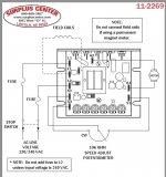
There's not a lot to take pictures of. However, I have this wiring diagram for the speed controller:

attachment.php


And a line from the directions:

"The chassis must be earth grounded. To ground the chassis, use a star washer beneath the head of at least one of the mounting screws to penetrate the anodized chassis surface and to reach bare metal."
 

Attachments

  • wire.jpg
    wire.jpg
    104.4 KB · Views: 180
To avoid these ads, REGISTER NOW!

MoonRise

Well-known member
Joined
Nov 5, 2010
Messages
4,046
Location
NJ
In general, you need to 'ground' all the AC stuff and generally any metal parts that have or could have AC on/in them.

You have the ground wire on the AC power cord and the directions for the DC speed controller board/box say "The chassis must be earth grounded". So, the chassis (metal 'frame') of the speed control box/board must be "grounded" to the AC ground wire from the wall/house.

You are using a 'standard' 3 prong/wire 120V AC wall plug/outlet to feed the saw/speed-controller?

If so, you have the 3 wires in the power cord, one "hot" wire and one "neutral" wire (the two 'blade' connectors on the plug) and one "ground" wire (the 'pin' connector on the plug, which is the green or bare wire typically, at least on the house-side of things).

Per the wiring diagram for the speed controller, the "hot" and the "neutral" wire go to L1 and L2 on the speed controller. Then you need to electrically connect the speed controller chassis and the power cord ground wire. This is for your safety (so you don't get shocked electrically from 120V AC power, if something is or goes wrong with the circuit or board or wiring), as well as sometimes the circuit board uses or depends on the "ground" to ensure the components on the board have the right relative voltages between components on the board.

Why do you have to use a screw and star washer to make the electrical ground connection to the chassis? Because the anodizing on the aluminum chassis is (mostly) an electrical insulator (anodizing is aluminum oxide, which is an electrical insulator). You have to use the metal screw to get to the actual aluminum of the chassis, and not just the 'coating' on the chassis.

Your DC motor connects to A1 and A2 from the speed controller.

I do not see any required "electrical ground" to/from the DC motor on the speed controller circuit diagram.

However, electrical safety usually requires all the metal pieces/parts to be "bonded" together electrically. Which usually means that the metal saw frame and the metal case of the motor get electrically connected to the green/bare wire from the wall plug/cord.

Unless the motor wiring diagram (which I don't see on the SurplusCenter webpage for the motor) specifically shows/says to connect any of the motor electrical connections to "ground", then do NOT do so.

The motor is a DC motor and should not be electrically connected to the AC wires. The metal case/chassis of the motor is usually connected to the green/bare wire though (for "bonding" the metal case/chassis to the ground wire).

Also, although I don't think this happened or had anything to do in this case at all, note that your 3/4 hp 90V DC motor will draw 7.8A DC. The speed controller notes ( http://www.surpluscenter.com/_MoreSpecs/as11-2269.pdf ) mention in the asterisk note on the specs that the 'optional' heatsink is required for outputs over 5A. You need the heatsink.
 
OP
R

Ryan

Administrator
Staff member
Joined
Jan 26, 2006
Messages
5,779
Location
Boulder/Koloa
In general, you need to 'ground' all the AC stuff and generally any metal parts that have or could have AC on/in them.

You have the ground wire on the AC power cord and the directions for the DC speed controller board/box say "The chassis must be earth grounded". So, the chassis (metal 'frame') of the speed control box/board must be "grounded" to the AC ground wire from the wall/house.

You are using a 'standard' 3 prong/wire 120V AC wall plug/outlet to feed the saw/speed-controller?

If so, you have the 3 wires in the power cord, one "hot" wire and one "neutral" wire (the two 'blade' connectors on the plug) and one "ground" wire (the 'pin' connector on the plug, which is the green or bare wire typically, at least on the house-side of things).

Per the wiring diagram for the speed controller, the "hot" and the "neutral" wire go to L1 and L2 on the speed controller. Then you need to electrically connect the speed controller chassis and the power cord ground wire. This is for your safety (so you don't get shocked electrically from 120V AC power, if something is or goes wrong with the circuit or board or wiring), as well as sometimes the circuit board uses or depends on the "ground" to ensure the components on the board have the right relative voltages between components on the board.

Why do you have to use a screw and star washer to make the electrical ground connection to the chassis? Because the anodizing on the aluminum chassis is (mostly) an electrical insulator (anodizing is aluminum oxide, which is an electrical insulator). You have to use the metal screw to get to the actual aluminum of the chassis, and not just the 'coating' on the chassis.

Your DC motor connects to A1 and A2 from the speed controller.

I do not see any required "electrical ground" to/from the DC motor on the speed controller circuit diagram.

However, electrical safety usually requires all the metal pieces/parts to be "bonded" together electrically. Which usually means that the metal saw frame and the metal case of the motor get electrically connected to the green/bare wire from the wall plug/cord.

Unless the motor wiring diagram (which I don't see on the SurplusCenter webpage for the motor) specifically shows/says to connect any of the motor electrical connections to "ground", then do NOT do so.

The motor is a DC motor and should not be electrically connected to the AC wires. The metal case/chassis of the motor is usually connected to the green/bare wire though (for "bonding" the metal case/chassis to the ground wire).

Also, although I don't think this happened or had anything to do in this case at all, note that your 3/4 hp 90V DC motor will draw 7.8A DC. The speed controller notes ( http://www.surpluscenter.com/_MoreSpecs/as11-2269.pdf ) mention in the asterisk note on the specs that the 'optional' heatsink is required for outputs over 5A. You need the heatsink.

I just got off the phone with Minarik - the people that make the controller... And, I'm even more stupid than I originally thought.

You, however, seem to have it between the ears. In other words, you are right.

Stupid me!
 

MoonRise

Well-known member
Joined
Nov 5, 2010
Messages
4,046
Location
NJ
I just got off the phone with Minarik - the people that make the controller... And, I'm even more stupid than I originally thought.

You, however, seem to have it between the ears. In other words, you are right.

Stupid me!

:thumbup:

also note: I -think- that type of DC motor controller will output 90V DC if fed from 120V AC, and will output 180V DC if fed from 240V AC.

Since the motor you listed is a 90V DC motor, only feed that controller board with 120V AC so you only get 90V DC output to the motor! (cause feeding 180V DC to a motor designed for 90V DC will also do bad things, in that case to the motor.)
 
To avoid these ads, REGISTER NOW!
Top Bottom